Page 7 of 4500

1.SYSTEM DESCRIPTION
HINT:
The skid control ECU is a single unit with ABS & TRACTION ACTUATOR.
The skid control ECU also works as a TPMS (Tire Pressure Monitor System) ECU.
The yaw rate sensor and deceleration sensor are combined and in a single unit. This unit
communicates with the skid control ECU through CAN communication.
a. ABS (Anti-lock Brake System)
The ABS helps prevent the wheels from locking when the brakes are applied firmly or when
braking on a slippery surface.
ECUSystem
ECMSkid Control ECUShift Position SignalCAN Communication
System
ECMSkid Control ECUThrottle Position SignalCAN Communication
System
ECMSkid Control ECUEngine Revolution SignalCAN Communication
System
ECMSkid Control ECUWater Temperature Sensor
SignalCAN Communication
System
ECMSkid Control ECUIntake Air Temperature Sensor
SignalCAN Communication
System
Skid Control ECUECMYaw Rate (Deceleration) SignalCAN Communication
System
Skid Control ECUECMVSC Data SignalCAN Communication
System
Skid Control ECUGate Way ECUBrake Warning Lamp ON
SignalBEAN System
Skid Control ECUGate Way ECUABS Warning Lamp ON SignalBEAN System
Skid Control ECUGate Way ECUTRAC OFF Indicator ON
SignalBEAN System
Skid Control ECUGate Way ECUSlip Indicator ON SignalBEAN System
Skid Control ECUGate Way ECUMulti Information display
SignalBEAN System
Page 11 of 4500
Fig. 7: ABS & TRACTION Actuator - Traction Control
Courtesy of TOYOTA MOTOR SALES, U.S.A., INC.
Operation description
The skid control ECU detects vehicle's slip condition by receiving signals from the speed sensor
<004400510047000300280026003000030059004c004400030026002400310003004600520050005000580051004c004600440057004c00520051001100030037004b004800030056004e004c00470003004600520051005700550052004f00030028002600
380003004600520051005700550052004f0056000300480051[gine torque with the ECM,
vehicle position with suspension control ECU via CAN communication, and oil pressure with the
pump and solenoid valve. The SLIP indicator lamp blinks when the system is operating. TRAC
OFF switch stops traction control operation.
e. VSC (Vehicle Stability Control)
The VSC system helps prevent the vehicle from slipping sideways as a result of strong front wheel skid or
stron
g rear wheel skid during cornering.
Page 12 of 4500

Fig. 8: ABS & TRACTION Actuator - Vehicle Stability Control
Courtesy of TOYOTA MOTOR SALES, U.S.A., INC.
Operation description
The skid control ECU determines vehicle condition by receiving signals from the speed sensor, yaw rate
and deceleration sensor and steering angle sensor. The skid control ECU controls engine torque with the
ECM, vehicle position with suspension control ECU via CAN communication, and oil pressure with the
pump and solenoid valve. The warning light comes on and the buzzer sounds when the system is
operating.
2.ABS with EBD & BA & TRAC & VSC OPERATION
a. Skid control ECU calculates vehicle stability tendency based on the signal of sensors, speed sensor,
yaw rate and deceleration sensor and steering angle sensor. And it judges whether the control of
engine output torque by electronic control throttle and of wheel brake pressure by brake actuator
will operate or not by the calculation results.
b. The SLIP indicator blinks and the VSC buzzer sounds to inform the driver that the VSC system is
operating. The SLIP indicator also blinks when TRAC is operating, and the operation being
performed is displayed.
3.FAIL SAFE FUNCTION
a. When a failure occurs in the ABS with BA & TRAC & VSC systems, the ABS warning light and
the VSC warning light turns on and the ABS with BA & TRAC & VSC operations are prohibited.
In addition to this, when there is a failure that disables the EBD operation, the brake warning light
also comes on and the EBD operation is prohibited (see FAIL
-SAFE CHART ).
b. If some control is prohibited due to a malfunction during it's operation, that control will be cut off
gradually not to change stability of vehicle suddenly.
4.PRE-COLLISION BRAKE ASSIST SYSTEM (w/ PRE-COLLISION BRAKE ASSIST SYSTEM)
Page 55 of 4500

HINT:
If a malfunction code is displayed during the DTC check, check the circuit indicated by the table below.
DIAGNOSTIC TROUBLE CODE CHART
SMF (BA-SOL)Turns TRAC solenoid SMF (BA-SOL)
ON / OFFOperation of solenoid (clicking sound)
can be heard
SMRTurns TRAC solenoid SMR ON / OFFOperation of solenoid (clicking sound)
can be heard
SOL RELAYTurns ABS solenoid relay ON / OFFOperation of solenoid (clicking sound)
can be heard
ABS MOT RELAYTurns ABS motor relay ON / OFFOperation of solenoid (clicking sound)
can be heard
ABS WARN LIGHTTurns ABS warning light ON / OFFObserve combination meter
VSC WARN LIGHTTurns VSC warning light ON / OFFObserve combination meter
VSC / TRC OFF INDTurns VSC / TRC OFF indicator ON /
OFFObserve combination meter
SLIP INDI LIGHTTurns SLIP indicator light ON / OFFObserve combination meter
BRAKE WRN LIGHTTurns BRAKE warning light ON / OFFObserve combination meter
VSC / BR WARN
BUZTurns VSC / BRAKE warning buzzer
ON / OFFBuzzer can be heard
STP LIGHT RELAYTurns stop light ON / OFFStop light come on
DTCDescription
DTC C0200/31, C0205/32RIGHT/LEFT FRONT SPEED SENSOR
DTC C0210/33, C0215/34RIGHT/LEFT REAR SPEED SENSOR
DTC C0226/21, C0236/22, C0246/23,
C0256/24, C1225/25
SFR/SFL/SRR/SRL/SM SOLENOID CIRCUIT
DTC C0273/13, C0274/14, C1361/91OPEN CIRCUIT IN ABS MOTOR RELAY CIRCUIT,
B+ SHORT CIRCUIT IN ABS MOTOR RELAY
CIRCUIT, SHORT CIRCUIT IN ABS MOTOR FAIL
SAFE RELAY CIRCUIT
DTC C0278/11, C0279/12OPEN/SHORT CIRCUIT IN ABS SOLENOID
RELAY CIRCUIT
DTC C1201/51ENGINE CONTROL SYSTEM MALFUNCTION
DTC C1203/53ECM COMMUNICATION CIRCUIT
MALFUNCTION
DTC C1210/36, C1336/39ZERO POINT CALIBRATION OF YAW
RATE/DECELERATION SENSOR UNDONE
DTC C1223/43ABS CONTROL SYSTEM MALFUNCTION
DTC C1231/31MALFUNCTION IN STEERING ANGLE SENSOR
CIRCUIT
Page 102 of 4500

HINT:
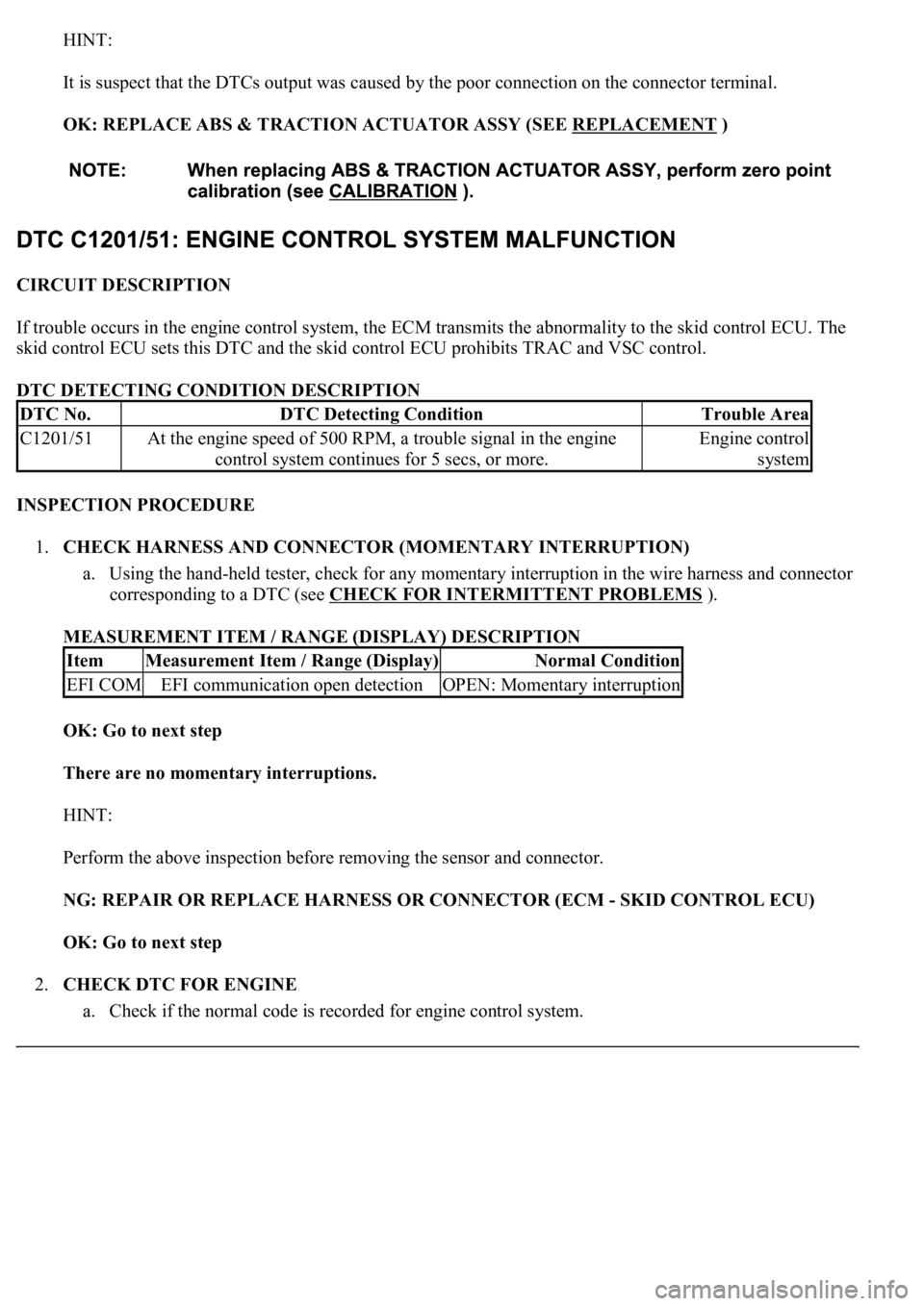
It is suspect that the DTCs output was caused by the poor connection on the connector terminal.
OK: REPLACE ABS & TRACTION ACTUATOR ASSY (SEE REPLACEMENT
)
CIRCUIT DESCRIPTION
If trouble occurs in the engine control system, the ECM transmits the abnormality to the skid control ECU. The
skid control ECU sets this DTC and the skid control ECU prohibits TRAC and VSC control.
DTC DETECTING CONDITION DESCRIPTION
INSPECTION PROCEDURE
1.CHECK HARNESS AND CONNECTOR (MOMENTARY INTERRUPTION)
a. Using the hand-held tester, check for any momentary interruption in the wire harness and connector
corresponding to a DTC (see CHECK FOR INTERMITTENT PROBLEMS
).
MEASUREMENT ITEM / RANGE (DISPLAY) DESCRIPTION
OK: Go to next step
There are no momentary interruptions.
HINT:
Perform the above inspection before removing the sensor and connector.
NG: REPAIR OR REPLACE HARNESS OR CONNECTOR (ECM - SKID CONTROL ECU)
OK: Go to next step
2.CHECK DTC FOR ENGINE
a. Check if the normal code is recorded for en
gine control system.
DTC No.DTC Detecting ConditionTrouble Area
C1201/51At the engine speed of 500 RPM, a trouble signal in the engine
control system continues for 5 secs, or more.Engine control
system
ItemMeasurement Item / Range (Display)Normal Condition
EFI COMEFI communication open detectionOPEN: Momentary interruption
Page 103 of 4500

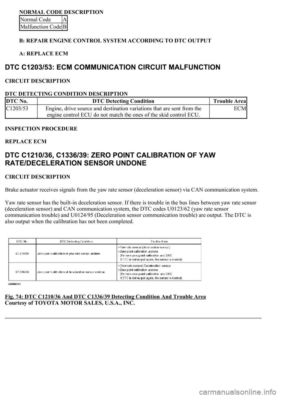
NORMAL CODE DESCRIPTION
B: REPAIR ENGINE CONTROL SYSTEM ACCORDING TO DTC OUTPUT
A: REPLACE ECM
CIRCUIT DESCRIPTION
DTC DETECTING CONDITION DESCRIPTION
INSPECTION PROCEDURE
REPLACE ECM
CIRCUIT DESCRIPTION
Brake actuator receives signals from the yaw rate sensor (deceleration sensor) via CAN communication system.
Yaw rate sensor has the built-in deceleration sensor. If there is trouble in the bus lines between yaw rate sensor
(deceleration sensor) and CAN communication system, the DTC codes U0123/62 (yaw rate sensor
communication trouble) and U0124/95 (Deceleration sensor communication trouble) are output. The DTC is
also output when the calibration has not been completed.
Fig. 74: DTC C1210/36 And DTC C1336/39 Detecting Condition And Trouble Area
Courtesy of TOYOTA MOTOR SALES, U.S.A., INC.
Normal CodeA
Malfunction CodeB
DTC No.DTC Detecting ConditionTrouble Area
C1203/53Engine, drive source and destination variations that are sent from the
engine control ECU do not match the ones of the skid control ECU.ECM
Page 192 of 4500
3.INSPECT HARNESS AND CONNECTOR (SKID CONTROL ECU - ECM)
a. Disconnect the slid control ECU connector.
b. Measure the resistance according to the value (s) in the table below.
Standard:
TESTER CONNECTION SPECIFIED CONDITION
c. Measure the resistance according to the value (s) in the table below.
Standard:
TESTER CONNECTION SPECIFIED CONDITION
NG: REPAIR OR REPLACE HARNESS OR CONNECTOR
Tester ConnectionSpecified Condition
D1-13 (TC) - E2-3 (TC)Below 1 ohms
Tester ConnectionSpecified Condition
D1-13 (TC) - Body ground1 Mohms or higher
Page 216 of 4500
By operating each of the A/C control switches as shown in the diagram below, it is possible to enter the
diagnostic check mode.
Fig. 11: Operation Methods Chart
Courtesy of TOYOTA MOTOR SALES, U.S.A., INC.
2.CHECK DLC3
a. The vehicle's ECM uses CAN and the to ISO 9141-2 for communication protocol. The terminal
arrangement of the DLC3 complies with SAE J1962 and meets the ISO 9141-2 format.