Page 1204 of 4500
1.JUNCTION CONNECTOR (D-CAN J/C, P-CAN J/C, LUG CAN J/C).
a. D-CAN J/C.
HINT:
The connectors connected to the CAN J/C can be distinguished by the colors of the bus lines
and the connecting side of the connector.
<0037004b00480003004600520051005100480046005700520055005600030046004400510003004500480003004600520051005100480046005700480047000300570052000300440051005c00030057004800550050004c00510044004f00560003005200
5100030057004b00480003005600440050004800030056004c[de.
D-CAN JUNCTION CONNECTORS COLORS DETAIL
D-CAN JUNCTION CONNECTORS COLORS DETAIL
HINT:
D-CAN J/C connectors (A side, w/earth terminal)Color (CAN-H
Side)Color (CAN-L
Side)
Suspension control ECU (1)BRY
Gateway ECULGL
CAN main bus line (bus line to connect D-CAN J/C and P-
CAN J/C)BW
(1)w/ Electronic Modulated Air Suspension.
D-CAN J/C connectors (B side, w/o earth terminal)Color (CAN-H Side)Color (CAN-L Side)
DLC3BW
Steering sensorLGL
Skid control ECUBRY
ECMRW
Page 1212 of 4500
Fig. 16: Identifying DCL3 Connector Terminals
Courtesy of TOYOTA MOTOR SALES, U.S.A., INC.
2.DLC3
a. Measure the resistance according to the value (s) in the table below.
Standard:
ECM CONNECTOR TERMINALS RESISTANCE
TerminalsWiring ColorConditionSpecified Condition
D1-6 (CANH) - D1-14 (CANL)B - WIgnition Switch OFF54 to 69 ohms
D1-6 (CANH) - D1-4 (CG)B - W-BIgnition Switch OFF1 kohms or more
D1-14 (CANL) - D1-4 (CG)W - W-BIgnition Switch OFF1 kohms or more
D1-6 (CANH) - D1-16 (BAT)B - BIgnition Switch OFF1 Mohms or more
D1-14 (CANL) - D1-16 (BAT)W - BIgnition Switch OFF1 Mohms or more
Page 1219 of 4500
TELEVISION CAMERA ECU CONNECTOR TERMINALS RESISTANCE
Fig. 22: Identifying ECM Connector Terminals
Courtesy of TOYOTA MOTOR SALES, U.S.A., INC.
8.ECM
a. Measure the resistance according to the value (s) in the table below.
Standard:
ECM CONNECTOR TERMINALS RESISTANCE
TerminalsWiring ColorConditionSpecified Condition
T24-8 (CANH) - T24-7 (CANL)LG - LIgnition Switch OFF54 to 69 ohms
T24-8 (CANH) - T25-8 (GND1)LG - W-BIgnition Switch OFF1 kohms or more
T24-7 (CANL) - T25-8 (GND1)L - W-BIgnition Switch OFF1 kohms or more
T24-8 (CANH) - T25-1 (+B)LG - RIgnition Switch OFF1 Mohms or more
T24-7 (CANL) - T25-1 (+B)L - RIgnition Switch OFF1 Mohms or more
TerminalsWiring ColorConditionSpecified Condition
E3-25 (CANH) - E3-24 (CANL)R- WIgnition Switch OFF54 to 69 ohms
E3-25 (CANH) - E3-2 (EC)R - W-BIgnition Switch OFF1 kohms or more
E3-24 (CANL) - E3-2 (EC)W - W-BIgnition Switch OFF1 kohms or more
Page 1223 of 4500

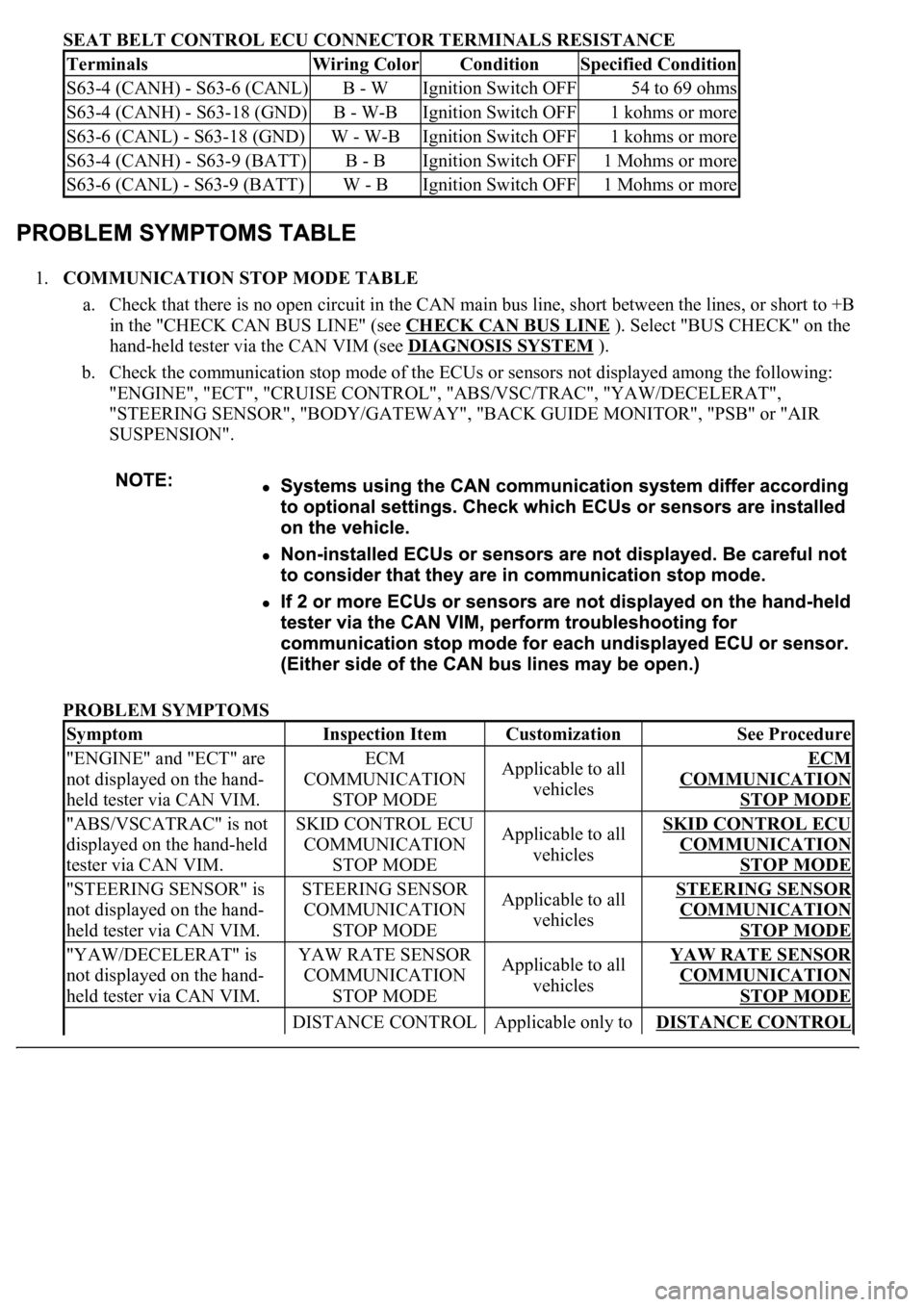
SEAT BELT CONTROL ECU CONNECTOR TERMINALS RESISTANCE
1.COMMUNICATION STOP MODE TABLE
a. Check that there is no open circuit in the CAN main bus line, short between the lines, or short to +B
in the "CHECK CAN BUS LINE" (see CHECK CAN BUS LINE
). Select "BUS CHECK" on the
hand-held tester via the CAN VIM (see DIAGNOSIS SYSTEM
).
b. Check the communication stop mode of the ECUs or sensors not displayed among the following:
"ENGINE", "ECT", "CRUISE CONTROL", "ABS/VSC/TRAC", "YAW/DECELERAT",
"STEERING SENSOR", "BODY/GATEWAY", "BACK GUIDE MONITOR", "PSB" or "AIR
SUSPENSION".
PROBLEM SYMPTOMS
TerminalsWiring ColorConditionSpecified Condition
S63-4 (CANH) - S63-6 (CANL)B - WIgnition Switch OFF54 to 69 ohms
S63-4 (CANH) - S63-18 (GND)B - W-BIgnition Switch OFF1 kohms or more
S63-6 (CANL) - S63-18 (GND)W - W-BIgnition Switch OFF1 kohms or more
S63-4 (CANH) - S63-9 (BATT)B - BIgnition Switch OFF1 Mohms or more
S63-6 (CANL) - S63-9 (BATT)W - BIgnition Switch OFF1 Mohms or more
SymptomInspection ItemCustomizationSee Procedure
"ENGINE" and "ECT" are
not displayed on the hand-
held tester via CAN VIM.ECM
COMMUNICATION
STOP MODEApplicable to all
vehiclesECM
COMMUNICATION
STOP MODE
"ABS/VSCATRAC" is not
displayed on the hand-held
tester via CAN VIM.SKID CONTROL ECU
COMMUNICATION
STOP MODEApplicable to all
vehiclesSKID CONTROL ECU
COMMUNICATION
STOP MODE
"STEERING SENSOR" is
not displayed on the hand-
held tester via CAN VIM.STEERING SENSOR
COMMUNICATION
STOP MODEApplicable to all
vehiclesSTEERING SENSOR
COMMUNICATION
STOP MODE
"YAW/DECELERAT" is
not displayed on the hand-
held tester via CAN VIM.YAW RATE SENSOR
COMMUNICATION
STOP MODEApplicable to all
vehiclesYAW RATE SENSOR
COMMUNICATION
STOP MODE
DISTANCE CONTROL Applicable only to DISTANCE CONTROL
Page 1226 of 4500
x: Not output
-: Undetectable
HINT:
see SKID CONTROL ECU COMMUNICATION STOP MODE .
see STEERING SENSOR COMMUNICATION STOP MODE .
see YAW RATE SENSOR COMMUNICATION STOP MODE .
see GATEWAY ECU COMMUNICATION STOP MODE .
see ECM COMMUNICATION STOP MODE .
see DISTANCE CONTROL ECU COMMUNICATION STOP MODE .
see SUSPENSION CONTROL ECU COMMUNICATION STOP MODE .
see TELEVISION CAMERA ECU COMMUNICATION STOP MODE .
see SEAT BELT CONTROL ECU COMMUNICATION STOP MODE .
Page 1230 of 4500
Fig. 30: ECUS And Sensors Checking Method Chart
Courtesy of TOYOTA MOTOR SALES, U.S.A., INC.
1.FAIL-SAFE FUNCTION
a. When communication fails in any of the CAN bus lines (communication lines) due to a short circuit
or other causes, the fail-safe function, which is specified for each system, operates to prevent the
system from malfunctioning.
b. Effects on each system when communication is impossible. (For further details, see the pages for
each system.)
FAIL-SAFE CHART
FunctionECM
Skid
Control
ECUSteering
SensorYaw
Rate
SensorDistance
Control
ECUTelevision
Camera
ECUSuspension
Control
ECUGateway
ECU
Seat
Belt
Control
ECUAction
unab
l
commu
VSC
Control
(Controls
driving force
while VSC
is in
operation)
RxTxRx VSC fun
stop
VSC
Control
(Controls
driving force
while VSC
is in
operation)
RxRx VSC fun
stop
Page 1232 of 4500

HINT:
Rx: Reception from each ECU (sensor).
Tx: Transmission to each ECU (sensor).
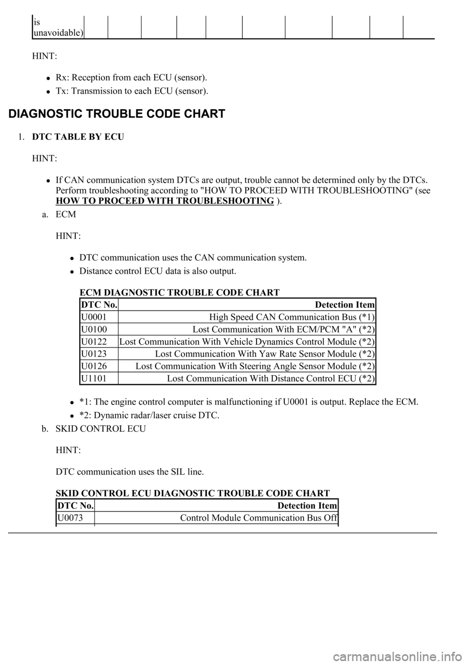
1.DTC TABLE BY ECU
HINT:
If CAN communication system DTCs are output, trouble cannot be determined only by the DTCs.
Perform troubleshooting according to "HOW TO PROCEED WITH TROUBLESHOOTING" (see
HOW TO PROCEED WITH TROUBLESHOOTING
).
a. ECM
HINT:
DTC communication uses the CAN communication system.
Distance control ECU data is also output.
ECM DIAGNOSTIC TROUBLE CODE CHART
*1: The engine control computer is malfunctioning if U0001 is output. Replace the ECM.
*2: Dynamic radar/laser cruise DTC.
b. SKID CONTROL ECU
HINT:
DTC communication uses the SIL line.
SKID CONTROL ECU DIAGNOSTIC TROUBLE CODE CHART
is
unavoidable)
DTC No.Detection Item
U0001High Speed CAN Communication Bus (*1)
U0100Lost Communication With ECM/PCM "A" (*2)
U0122Lost Communication With Vehicle Dynamics Control Module (*2)
U0123Lost Communication With Yaw Rate Sensor Module (*2)
U0126Lost Communication With Steering Angle Sensor Module (*2)
U1101Lost Communication With Distance Control ECU (*2)
DTC No.Detection Item
U0073Control Module Communication Bus Off
Page 1233 of 4500

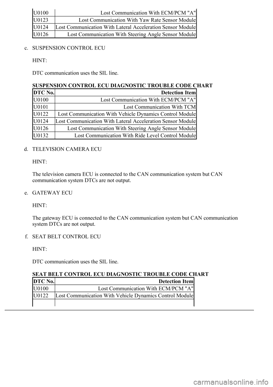
c. SUSPENSION CONTROL ECU
HINT:
DTC communication uses the SIL line.
SUSPENSION CONTROL ECU DIAGNOSTIC TROUBLE CODE CHART
d. TELEVISION CAMERA ECU
HINT:
The television camera ECU is connected to the CAN communication system but CAN
communication system DTCs are not output.
e. GATEWAY ECU
HINT:
The gateway ECU is connected to the CAN communication system but CAN communication
system DTCs are not output.
f. SEAT BELT CONTROL ECU
HINT:
DTC communication uses the SIL line.
SEAT BELT CONTROL ECU DIAGNOSTIC TROUBLE CODE CHART
U0100Lost Communication With ECM/PCM "A"
U0123Lost Communication With Yaw Rate Sensor Module
U0124Lost Communication With Lateral Acceleration Sensor Module
U0126Lost Communication With Steering Angle Sensor Module
DTC No.Detection Item
U0100Lost Communication With ECM/PCM "A"
U0101Lost Communication With TCM
U0122Lost Communication With Vehicle Dynamics Control Module
U0124Lost Communication With Lateral Acceleration Sensor Module
U0126Lost Communication With Steering Angle Sensor Module
U0132Lost Communication With Ride Level Control Module
DTC No.Detection Item
U0100Lost Communication With ECM/PCM "A"
U0122Lost Communication With Vehicle Dynamics Control Module