Page 2854 of 4500
c. Connect positive (+) lead to the terminal of solenoid connector, negative (-) lead to the solenoid
body.
OK:
The solenoid makes an operating noise.
Fig. 157: Inspecting Shift Solenoid Valve (SR)
Courtesy of TOYOTA MOTOR SALES, U.S.A., INC.
NG: REPLACE SHIFT SOLENOID VALVE (SR)
OK: REPAIR OR REPLACE TRANSMISSION WIRE (See step 5 on REPLACEMENT
)
DTC P2714: PRESSURE CONTROL SOLENOID "D" PERFORMANCE (SHIFT SOLENOID VALVE
SLT)
SYSTEM DESCRIPTION
Tester ConnectionSpecified Condition 20°C (68°F)
Solenoid Connector (SR) - Solenoid Body (SR)11 to 15ohms
Page 2862 of 4500
OK: Go to next step
3.INSPECT TRANSMISSION VALVE BODY ASSY (See chapter 2 in PROBLEM
SYMPTOMS TABLE )
OK:
There are no foreign objects on each valve and they operate smoothly.
NG: REPAIR OR REPLACE TRANSMISSION VALVE BODY ASSY (See step 6 on
REPLACEMENT
)
OK: Go to next step
4.INSPECT TORQUE CONVERTER CLUTCH ASSY (See INSPECTION
)
OK:
The torque converter clutch operates normally.
NG: REPLACE TORQUE CONVERTER CLUTCH ASSY
OK: REPAIR OR REPLACE AUTOMATIC TRANSMISSION ASSY (See
COMPONENTS
)
DTC P2716: PRESSURE CONTROL SOLENOID "D" ELECTRICAL (SHIFT SOLENOID SLT)
CIRCUIT DESCRIPTION
See DTC P2714 PRESSURE CONTROL SOLENOID "D" PERFORMANCE (SHIFT SOLENOID
VALVE SLT) .
Fig. 166: DTC Reference Chart
Courtesy of TOYOTA MOTOR SALES, U.S.A., INC.
MONITOR DESCRIPTION
When an open or short in the linear solenoid valve (SLT) circuit is detected, the ECM interprets this as a fault.
The ECM will turn ON the MIL and store the DTC.
MONITOR STRATEGY
Page 2867 of 4500
Fig. 171: Tester Connection Reference Chart
Courtesy of TOYOTA MOTOR SALES, U.S.A., INC.
NG: REPAIR OR REPLACE HARNESS OR CONNECTOR (See ELECTRONIC CIRCUIT
INSPECTION PROCEDURE )
OK: REPLACE ECM (See REPLACEMENT
)
3.INSPECT SHIFT SOLENOID VALVE (SLT)
a. Remove the shift solenoid valve (SLT).
b. Measure the resistance according to the value(s) in the table below.
Standard:
SHIFT SOLENOID VALVE (SLT) - RESISTANCE TABLE
c. Connect the positive (+) lead with a 21 W bulb to terminal 2 and the negative (-) lead to terminal 1
of the solenoid valve connector, then check the movement of the valve.
OK:
The solenoid makes an operating noise.
Tester ConnectionSpecified Condition 20°C (68°F)
1 - 25.0 to 5.6 ohms
Page 2869 of 4500
OK: REPAIR OR REPLACE TRANSMISSION WIRE (See step 5 on REPLACEMENT)
DTC P2757: TORQUE CONVERTER CLUTCH PRESSURE CONTROL SOLENOID
PERFORMANCE (SHIFT SOLENOID VALVE SLU)
SYSTEM DESCRIPTION
The ECM uses the signals from the throttle position sensor, Air-flow meter, turbine (input) speed sensor, output
speed sensor and crankshaft position sensor to monitor the engagement condition of the lock-up clutch.
Then the ECM compares the engagement condition of the lock-up clutch with the lock-up schedule in the ECM
memory to detect a mechanical problems of the shift solenoid valve SLU, valve body and torque converter
clutch.
Fig. 173: Identifying Manual Transmission
Courtesy of TOYOTA MOTOR SALES, U.S.A., INC.
Page 2877 of 4500

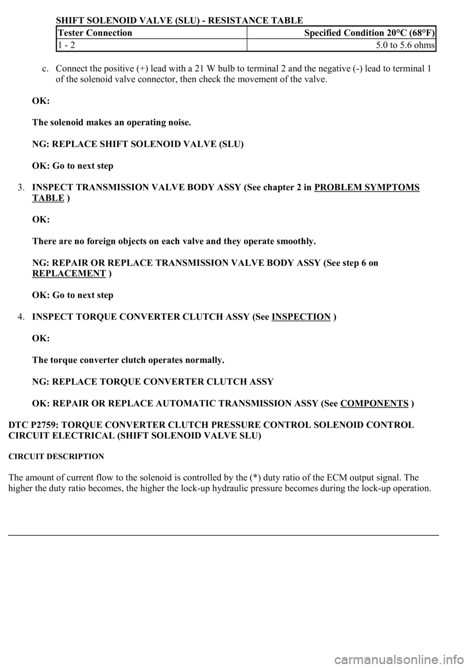
SHIFT SOLENOID VALVE (SLU) - RESISTANCE TABLE
c. Connect the positive (+) lead with a 21 W bulb to terminal 2 and the negative (-) lead to terminal 1
of the solenoid valve connector, then check the movement of the valve.
OK:
The solenoid makes an operating noise.
NG: REPLACE SHIFT SOLENOID VALVE (SLU)
OK: Go to next step
3.INSPECT TRANSMISSION VALVE BODY ASSY (See chapter 2 in PROBLEM SYMPTOMS
TABLE )
OK:
There are no foreign objects on each valve and they operate smoothly.
NG: REPAIR OR REPLACE TRANSMISSION VALVE BODY ASSY (See step 6 on
REPLACEMENT
)
OK: Go to next step
4.INSPECT TORQUE CONVERTER CLUTCH ASSY (See INSPECTION
)
OK:
The torque converter clutch operates normally.
NG: REPLACE TORQUE CONVERTER CLUTCH ASSY
OK: REPAIR OR REPLACE AUTOMATIC TRANSMISSION ASSY (See COMPONENTS
)
DTC P2759: TORQUE CONVERTER CLUTCH PRESSURE CONTROL SOLENOID CONTROL
CIRCUIT ELECTRICAL (SHIFT SOLENOID VALVE SLU)
CIRCUIT DESCRIPTION
The amount of current flow to the solenoid is controlled by the (*) duty ratio of the ECM output signal. The
hi
gher the duty ratio becomes, the higher the lock-up hydraulic pressure becomes during the lock-up operation.
Tester ConnectionSpecified Condition 20°C (68°F)
1 - 25.0 to 5.6 ohms
Page 2883 of 4500

Courtesy of TOYOTA MOTOR SALES, U.S.A., INC.
Standard:
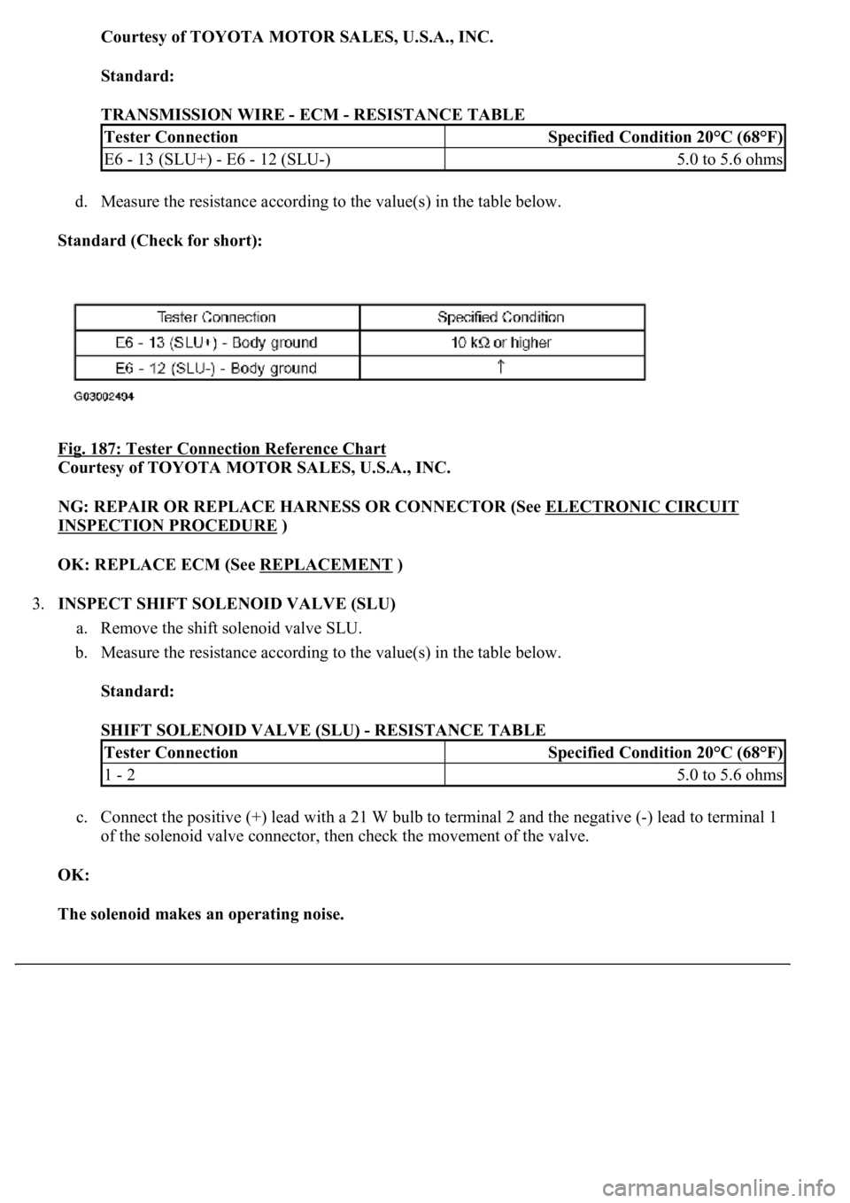
TRANSMISSION WIRE - ECM - RESISTANCE TABLE
d. Measure the resistance according to the value(s) in the table below.
Standard (Check for short):
Fig. 187: Tester Connection Reference Chart
Courtesy of TOYOTA MOTOR SALES, U.S.A., INC.
NG: REPAIR OR REPLACE HARNESS OR CONNECTOR (See ELECTRONIC CIRCUIT
INSPECTION PROCEDURE )
OK: REPLACE ECM (See REPLACEMENT
)
3.INSPECT SHIFT SOLENOID VALVE (SLU)
a. Remove the shift solenoid valve SLU.
b. Measure the resistance according to the value(s) in the table below.
Standard:
SHIFT SOLENOID VALVE (SLU) - RESISTANCE TABLE
c. Connect the positive (+) lead with a 21 W bulb to terminal 2 and the negative (-) lead to terminal 1
of the solenoid valve connector, then check the movement of the valve.
OK:
The solenoid makes an operating noise.
Tester ConnectionSpecified Condition 20°C (68°F)
E6 - 13 (SLU+) - E6 - 12 (SLU-)5.0 to 5.6 ohms
Tester ConnectionSpecified Condition 20°C (68°F)
1 - 25.0 to 5.6 ohms
Page 2885 of 4500
OK: REPAIR OR REPLACE TRANSMISSION WIRE (See step 5 on REPLACEMENT)
TRANSMISSION CONTROL SWITCH CIRCUIT
CIRCUIT DESCRIPTION
When moving the shift lever into the S position using the transmission control switch, it is possible to switch the
shift range position between "1" (first range) and "6" (sixth range).
Shifting up "+" once raises one shift range position, and shifting down "-" lowers one shift range position.
WIRING DIAGRAM
Page 2931 of 4500
Fig. 25: Applying Battery Positive Voltage Across Terminals
Courtesy of TOYOTA MOTOR SALES, U.S.A., INC.
REPLACEMENT
1.REMOVE V-BANK COVER
2.REMOVE VENTILATION VALVE SUB-ASSY
a. Disconnect the ventilation hose from the ventilation valve.
b. Remove the ventilation valve cover.
c. Remove the ventilation valve.
3.INSTALL VENTILATION VALVE SUB-ASSY
a. Install the ventilation valve.
1. Apply adhesive to 2 or 3 threads of the valve.
Adhesive: Part No. 08833-00070, THREE BOND 1324 or equivalent