Page 2748 of 4500

Courtesy of TOYOTA MOTOR SALES, U.S.A., INC.
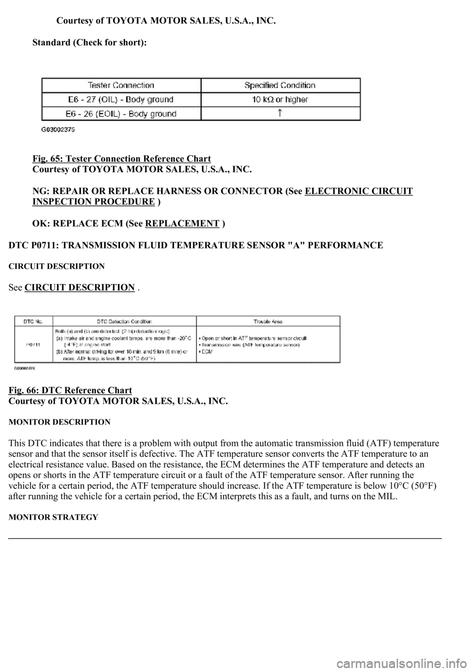
Standard (Check for short):
Fig. 65: Tester Connection Reference Chart
Courtesy of TOYOTA MOTOR SALES, U.S.A., INC.
NG: REPAIR OR REPLACE HARNESS OR CONNECTOR (See ELECTRONIC CIRCUIT
INSPECTION PROCEDURE )
OK: REPLACE ECM (See REPLACEMENT
)
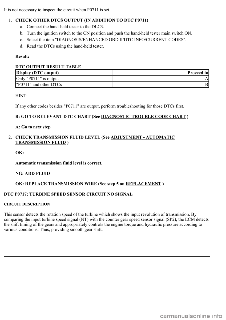
DTC P0711: TRANSMISSION FLUID TEMPERATURE SENSOR "A" PERFORMANCE
CIRCUIT DESCRIPTION
See CIRCUIT DESCRIPTION .
Fig. 66: DTC Reference Chart
Courtesy of TOYOTA MOTOR SALES, U.S.A., INC.
MONITOR DESCRIPTION
This DTC indicates that there is a problem with output from the automatic transmission fluid (ATF) temperature
sensor and that the sensor itself is defective. The ATF temperature sensor converts the ATF temperature to an
electrical resistance value. Based on the resistance, the ECM determines the ATF temperature and detects an
opens or shorts in the ATF temperature circuit or a fault of the ATF temperature sensor. After running the
vehicle for a certain period, the ATF temperature should increase. If the ATF temperature is below 10°C (50°F)
after running the vehicle for a certain period, the ECM interprets this as a fault, and turns on the MIL.
MONITOR STRATEGY
Page 2751 of 4500

It is not necessary to inspect the circuit when P0711 is set.
1.CHECK OTHER DTCS OUTPUT (IN ADDITION TO DTC P0711)
a. Connect the hand-held tester to the DLC3.
b. Turn the ignition switch to the ON position and push the hand-held tester main switch ON.
c. Select the item "DIAGNOSIS/ENHANCED OBD II/DTC INFO/CURRENT CODES".
d. Read the DTCs using the hand-held tester.
Result:
DTC OUTPUT RESULT TABLE
HINT:
If any other codes besides "P0711" are output, perform troubleshooting for those DTCs first.
B: GO TO RELEVANT DTC CHART (See DIAGNOSTIC TROUBLE CODE CHART
)
A: Go to next step
2.CHECK TRANSMISSION FLUID LEVEL (See ADJUSTMENT
- AUTOMATIC
TRANSMISSION FLUID )
OK:
Automatic transmission fluid level is correct.
NG: ADD FLUID
OK: REPLACE TRANSMISSION WIRE (See step 5 on REPLACEMENT
)
DTC P0717: TURBINE SPEED SENSOR CIRCUIT NO SIGNAL
CIRCUIT DESCRIPTION
This sensor detects the rotation speed of the turbine which shows the input revolution of transmission. By
comparing the input turbine speed signal (NT) with the counter gear speed sensor signal (SP2), the ECM detects
the shift timing of the gears and appropriately controls the engine torque and hydraulic pressure according to
various conditions. Thus, providin
g smooth gear shift.
Display (DTC output)Proceed to
Only "P0711" is outputA
"P0711" and other DTCsB
Page 2759 of 4500

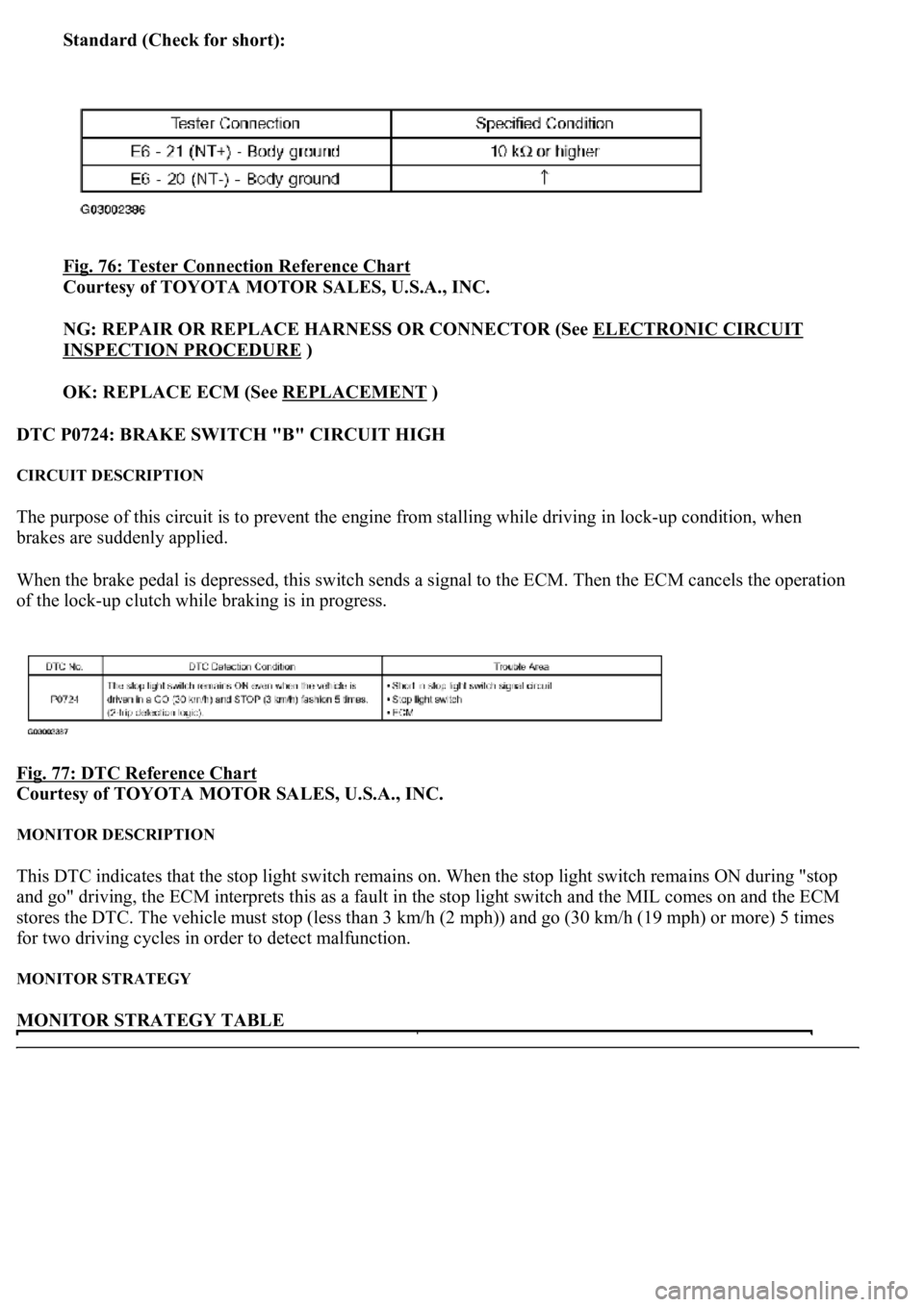
Standard (Check for short):
Fig. 76: Tester Connection Reference Chart
Courtesy of TOYOTA MOTOR SALES, U.S.A., INC.
NG: REPAIR OR REPLACE HARNESS OR CONNECTOR (See ELECTRONIC CIRCUIT
INSPECTION PROCEDURE )
OK: REPLACE ECM (See REPLACEMENT
)
DTC P0724: BRAKE SWITCH "B" CIRCUIT HIGH
CIRCUIT DESCRIPTION
The purpose of this circuit is to prevent the engine from stalling while driving in lock-up condition, when
brakes are suddenly applied.
When the brake pedal is depressed, this switch sends a signal to the ECM. Then the ECM cancels the operation
of the lock-up clutch while braking is in progress.
Fig. 77: DTC Reference Chart
Courtesy of TOYOTA MOTOR SALES, U.S.A., INC.
MONITOR DESCRIPTION
This DTC indicates that the stop light switch remains on. When the stop light switch remains ON during "stop
and go" driving, the ECM interprets this as a fault in the stop light switch and the MIL comes on and the ECM
stores the DTC. The vehicle must stop (less than 3 km/h (2 mph)) and go (30 km/h (19 mph) or more) 5 times
for two driving cycles in order to detect malfunction.
MONITOR STRATEGY
MONITOR STRATEGY TABLE
Page 2764 of 4500
OK: REPLACE ECM (See REPLACEMENT)
DTC P0729: GEAR 6 INCORRECT RATIO
SYSTEM DESCRIPTION
The ECM uses signals from the output speed sensor SP2 and input speed sensor NT to detect the actual gear
position (1st, 2nd, 3rd, 4th, 5th or 6th gear). Then the ECM compares the actual gear with the shift schedule in
the ECM memory to detect mechanical problems of the shift solenoid valves, valve body or automatic
transmission (clutch, brake or gear, etc.).
Fig. 83: Identifying Valve Body
Courtesy of TOYOTA MOTOR SALES, U.S.A., INC.
Page 2769 of 4500

OK:
Gear position changes in accordance with the tester command
NG: REPAIR OR REPLACE TRANSMISSION VALVE BODY ASSY (See step 6 on
REPLACEMENT
)
OK: Go to next step
3.CLEAR THE DTC AND RUNNING TEST
a. Clear the DTC, and check DTC again after conducting the "MONITOR DRIVE PATTERN FOR
ECT TEST" (see MONITOR DRIVE PATTERN
).
OK:
No DTC code
NG: REPAIR OR REPLACE TRANSMISSION VALVE BODY ASSY (See step 6 on
REPLACEMENT
)
OK: END
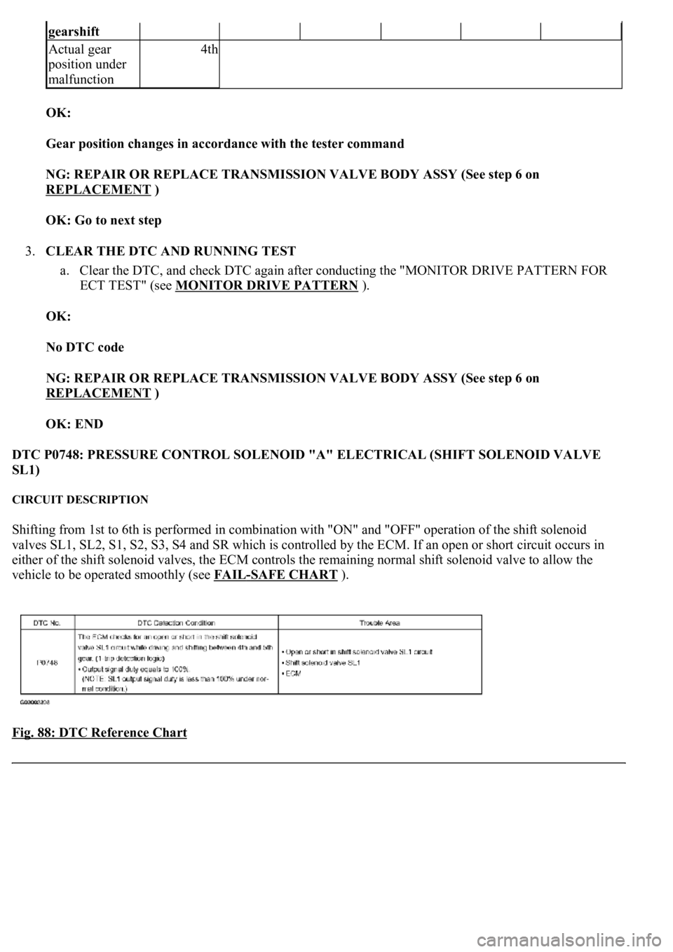
DTC P0748: PRESSURE CONTROL SOLENOID "A" ELECTRICAL (SHIFT SOLENOID VALVE
SL1)
CIRCUIT DESCRIPTION
Shifting from 1st to 6th is performed in combination with "ON" and "OFF" operation of the shift solenoid
valves SL1, SL2, S1, S2, S3, S4 and SR which is controlled by the ECM. If an open or short circuit occurs in
either of the shift solenoid valves, the ECM controls the remaining normal shift solenoid valve to allow the
vehicle to be operated smoothly (see FAIL
-SAFE CHART ).
Fig. 88: DTC Reference Chart
gearshift
Actual gear
position under
malfunction4th
Page 2774 of 4500
Fig. 93: Tester Connection Reference Chart
Courtesy of TOYOTA MOTOR SALES, U.S.A., INC.
NG: REPAIR OR REPLACE HARNESS OR CONNECTOR (See ELECTRONIC CIRCUIT
INSPECTION PROCEDURE )
OK: REPLACE ECM (See REPLACEMENT
)
3.INSPECT SHIFT SOLENOID VALVE (SL1)
a. Remove the shift solenoid valve SL1.
b. Measure the resistance according to the value(s) in the table below.
Standard:
SHIFT SOLENOID VALVE (SL1) - RESISTANCE TABLE
c. Connect the positive (+) lead with a 21 W bulb to terminal 2 and the negative (-) lead to terminal 1
of the solenoid valve connector, then check the movement of the valve.
OK:
The solenoid makes an operating noise.
Tester ConnectionSpecified Condition 20°C (68°F)
1 - 25.0 to 5.6 ohms
Page 2776 of 4500
OK: REPAIR OR REPLACE TRANSMISSION WIRE (See step 5 on REPLACEMENT)
DTC P0751: SHIFT SOLENOID "A" PERFORMANCE (SHIFT SOLENOID VALVE S1)
SYSTEM DESCRIPTION
The ECM uses signals from the output shaft speed sensor and input speed sensor to detect the actual gear
position (1st, 2nd, 3rd, 4th, 5th or 6th gear).
Then the ECM compares the actual gear with the shift schedule in the ECM memory to detect mechanical
problems of the shift solenoid valves and valve body.
Fig. 95: DTC Reference Chart
Courtesy of TOYOTA MOTOR SALES, U.S.A., INC.
HINT:
Gear positions in the event of a solenoid valve mechanical problem:
Fig. 96: Gear Position Specification
Courtesy of TOYOTA MOTOR SALES, U.S.A., INC.
Gear position during fail-safe operation:
If an
y malfunction is detected, the ECM changes into the fail-safe mode to shift into the gear positions as
Page 2783 of 4500
Fig. 100: Inspecting Shift Solenoid Valve (S1)
Courtesy of TOYOTA MOTOR SALES, U.S.A., INC.
NG: REPLACE SHIFT SOLENOID VALVE (S1)
OK: Go to next step
3.INSPECT TRANSMISSION VALVE BODY ASSY (See chapter 2 in PROBLEM SYMPTOMS
TABLE )
OK:
There are no foreign objects on each valve and they operate smoothly.
NG: REPAIR OR REPLACE TRANSMISSION VALVE BODY ASSY (See step 6 on
REPLACEMENT
)
OK: Go to next step
4.INSPECT TORQUE CONVERTER CLUTCH ASSY (See INSPECTION
)