Page 2525 of 4500
OK: Go To Next Step.
3.CHECK HARNESS AND CONNECTOR (TC of DLC3 - BODY GROUND)
a. Measure the resistance according to the value(s) in the table below.
Standard:
ECM CONNECTOR TERMINALS RESISTANCE SPECIFICATION
Fig. 88: Identifying DLC3 Connector (TC) Terminals
Courtesy of TOYOTA MOTOR SALES, U.S.A., INC.
NG: REPAIR OR REPLACE WIRE HARNESS AND EACH ECU
OK: REPLACE ECM (SEE REPLACEMENT
)
Tester connectionConditionSpecified condition
TC (D1-13) - Body groundAlways10 kohms or higher
Page 2576 of 4500

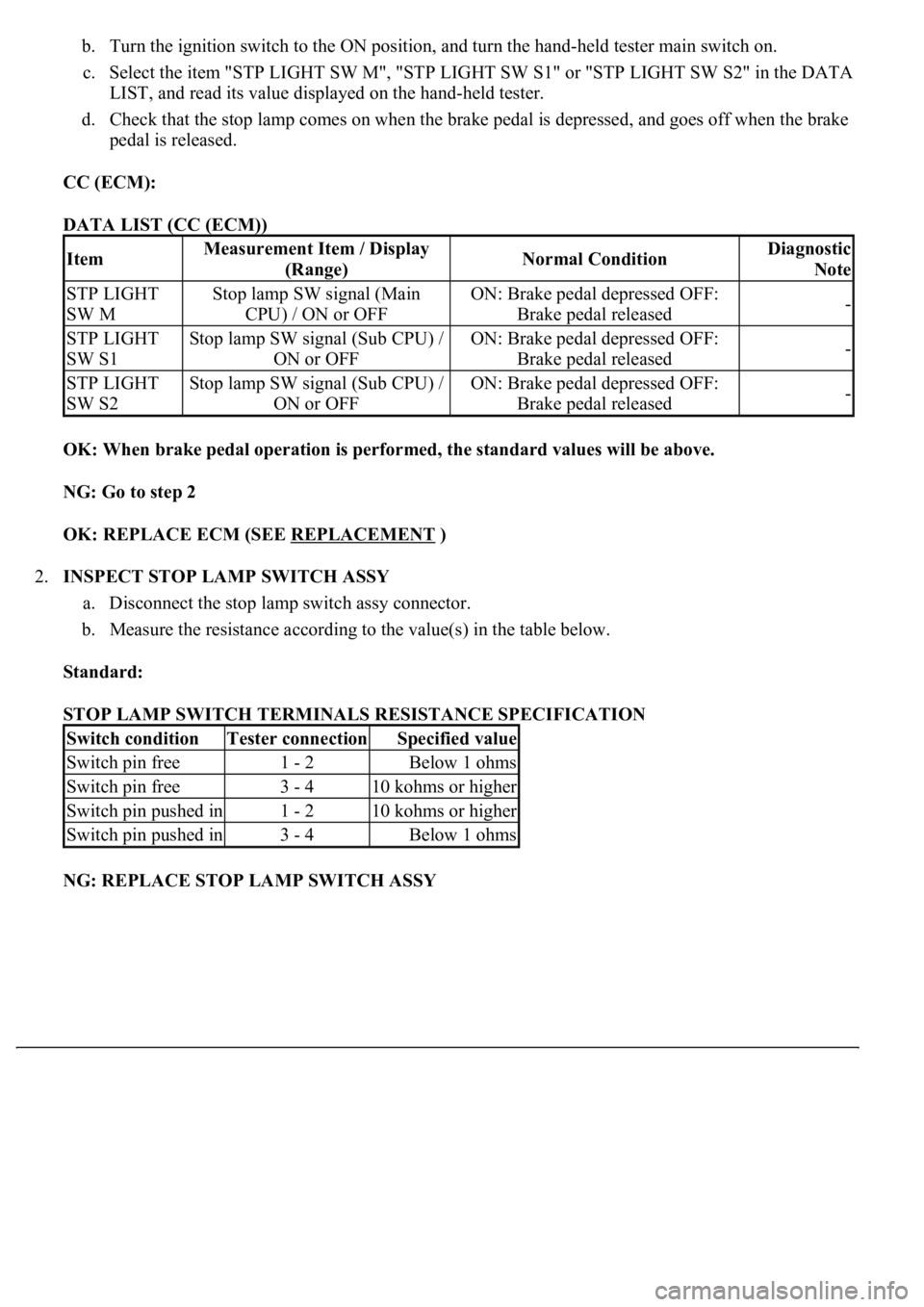
b. Turn the ignition switch to the ON position, and turn the hand-held tester main switch on.
c. Select the item "STP LIGHT SW M", "STP LIGHT SW S1" or "STP LIGHT SW S2" in the DATA
LIST, and read its value displayed on the hand-held tester.
d. Check that the stop lamp comes on when the brake pedal is depressed, and goes off when the brake
pedal is released.
CC (ECM):
DATA LIST (CC (ECM))
OK: When brake pedal operation is performed, the standard values will be above.
NG: Go to step 2
OK: REPLACE ECM (SEE REPLACEMENT
)
2.INSPECT STOP LAMP SWITCH ASSY
a. Disconnect the stop lamp switch assy connector.
b. Measure the resistance according to the value(s) in the table below.
Standard:
STOP LAMP SWITCH TERMINALS RESISTANCE SPECIFICATION
NG: REPLACE STOP LAMP SWITCH ASSY
ItemMeasurement Item / Display
(Range)Normal ConditionDiagnostic
Note
STP LIGHT
SW MStop lamp SW signal (Main
CPU) / ON or OFFON: Brake pedal depressed OFF:
Brake pedal released-
STP LIGHT
SW S1Stop lamp SW signal (Sub CPU) /
ON or OFFON: Brake pedal depressed OFF:
Brake pedal released-
STP LIGHT
SW S2Stop lamp SW signal (Sub CPU) /
ON or OFFON: Brake pedal depressed OFF:
Brake pedal released-
Switch conditionTester connectionSpecified value
Switch pin free1 - 2Below 1 ohms
Switch pin free3 - 410 kohms or higher
Switch pin pushed in1 - 210 kohms or higher
Switch pin pushed in3 - 4Below 1 ohms
Page 2581 of 4500
Courtesy of TOYOTA MOTOR SALES, U.S.A., INC.
A: REPLACE ECM (SEE REPLACEMENT
)
5.INSPECT DRIVER SIDE J/B
a. Measure the voltage according to the value(s) in the table below.
Fig. 50: Identifying Driver Side Junction Block ECU Connector Terminals
Courtesy of TOYOTA MOTOR SALES, U.S.A., INC.
Standard:
TESTER CONNECTION SPECIFICATION
NG: Go to step 6
Pedal conditionTester connectionSpecification
DepressedD3-12 (STPO) - Body ground10 to 14V
ReleasedD3-12 (STPO) - Body groundBelow 1 V
Page 2583 of 4500
CIRCUIT DESCRIPTION
This DTC indicates a malfunction in the ECM.
HINT:
The ECM receives signals from each sensor to control all the functions of the cruise control with the
microcomputer.
When a malfunction is detected, fail-safe remains on until the ignition switch is turned off.
Fig. 52: DTC P0607 Problem Symptom Diagnostic Chart
Courtesy of TOYOTA MOTOR SALES, U.S.A., INC.
INSPECTION PROCEDURE
1.REPLACE ECM (SEE REPLACEMENT
)
CIRCUIT DESCRIPTION
The distance control ECU receives information about the area in front of the vehicle from the millimeter wave
radar sensor and then sends a brake control demand signal (deceleration demand) and diagnosis signals, such as
millimeter wave radar sensor grime or millimeter wave radar sensor malfunction, to the ECM.
Page 2586 of 4500
4. Clear the DTC and then recheck for DTCs.
OK: DTC is not output.
HINT:
If DTC P1617 is still output after performing the above procedures, replace the distance control
ECU.
If the DTC P1617 is still output after replacing the distance control ECU, replace the ECM.
NG: REPLACE CRUISE CONTROL ECU ASSY (SEE REPLACEMENT
)
OK: SYSTEM OK
CIRCUIT DESCRIPTION
The skid control ECU sends signals such as cruise control cancel demand signal, brake operation demand
response signal from the ECM, etc. to the ECM when the dynamic radar cruise control system is in operation.
Fig. 55: DTC P1630 And U0122 Problem Symptom Diagnostic Chart
Courtesy of TOYOTA MOTOR SALES, U.S.A., INC.
INSPECTION PROCEDURE
HINT:
This circuit uses CAN for communication. Therefore, if there are any malfunctions in the communication
circuit, one or more DTCs in the CAN communication system is/are output.
1.GO TO CAN COMMUNICATION SYSTEM (SEE PRECAUTION
)
Page 2593 of 4500
Fig. 64: Signal Waveform Graph
Courtesy of TOYOTA MOTOR SALES, U.S.A., INC.
OK: REPLACE CRUISE CONTROL ECU ASSY (SEE REPLACEMENT
)
CIRCUIT DESCRIPTION
The millimeter wave radar sensor and cruise control ECU (distance control ECU) transmit the data for general
vehicle control and diagnosis function along the communication line.
The cruise control ECU (distance control ECU) determines the presumed R information based on the signal
from the steering wheel and yaw rate sensor.
The cruise control ECU (distance control ECU) transmits the current vehicle speed and presumed R information
to the millimeter wave radar sensor.
Page 2597 of 4500
CRUISE CONTROL ECU TERMINALS VOLTAGE SPECIFICATION
d. Check the signal waveform between terminal LRRD (D2-23) of the cruise control ECU (distance
control ECU) and body ground.
OK:
A waveform similar to that in the illustration to the left is output.
HINT:
Gauge set: 2 V/DIV, 5 ms/DIV
Condition: Ignition switch ON
NG: REPLACE CRUISE CONTROL ECU ASSY (SEE REPLACEMENT
)
Fig. 69: Reconnecting Cruise Control ECU (Distance Control ECU) Connector
Tester connectionConditionSpecified value
D2-13 (IGB) - Body groundIgnition SW ON10 to 14V
Page 2613 of 4500
Result:
RESULT DETAIL
B: Go to step 2
C: REPLACE CRUISE CONTROL MAIN SWITCH ASSY (SEE REPLACEMENT
)
A: PROCEED TO NEXT CIRCUIT INSPECTION SHOWN IN PROBLEM SYMPTOMS TABLE
2.INSPECT CRUISE CONTROL MAIN SWITCH ASSY
a. Disconnect the cruise control main switch connector.
Fig. 84: Checking Cruise Control Main Switch Assy
Courtesy of TOYOTA MOTOR SALES, U.S.A., INC.
b. Measure the resistance according to the value(s) in the table below.
Standard:
CRUISE CONTROL MAIN SWITCH CONNECTOR TERMINALS RESISTANCE
OKA
NG (All items are defective)B
NG (One to four items are defective)C
Switch conditionTester connectionResistance (ohms)
NeutralA-2 - A-3, A-3 - A-410 kohms or higher
RES/ACCA-2 - A-3210 to 270
SET/COASTA-2 - A-3560 to 700
CANCELA-2 - A-31,380 to 1,700
Main Switch OFFA-2 - A-310 kohms or higher
Main Switch ONA-2 - A-3Below 1 ohms