Page 2408 of 4500

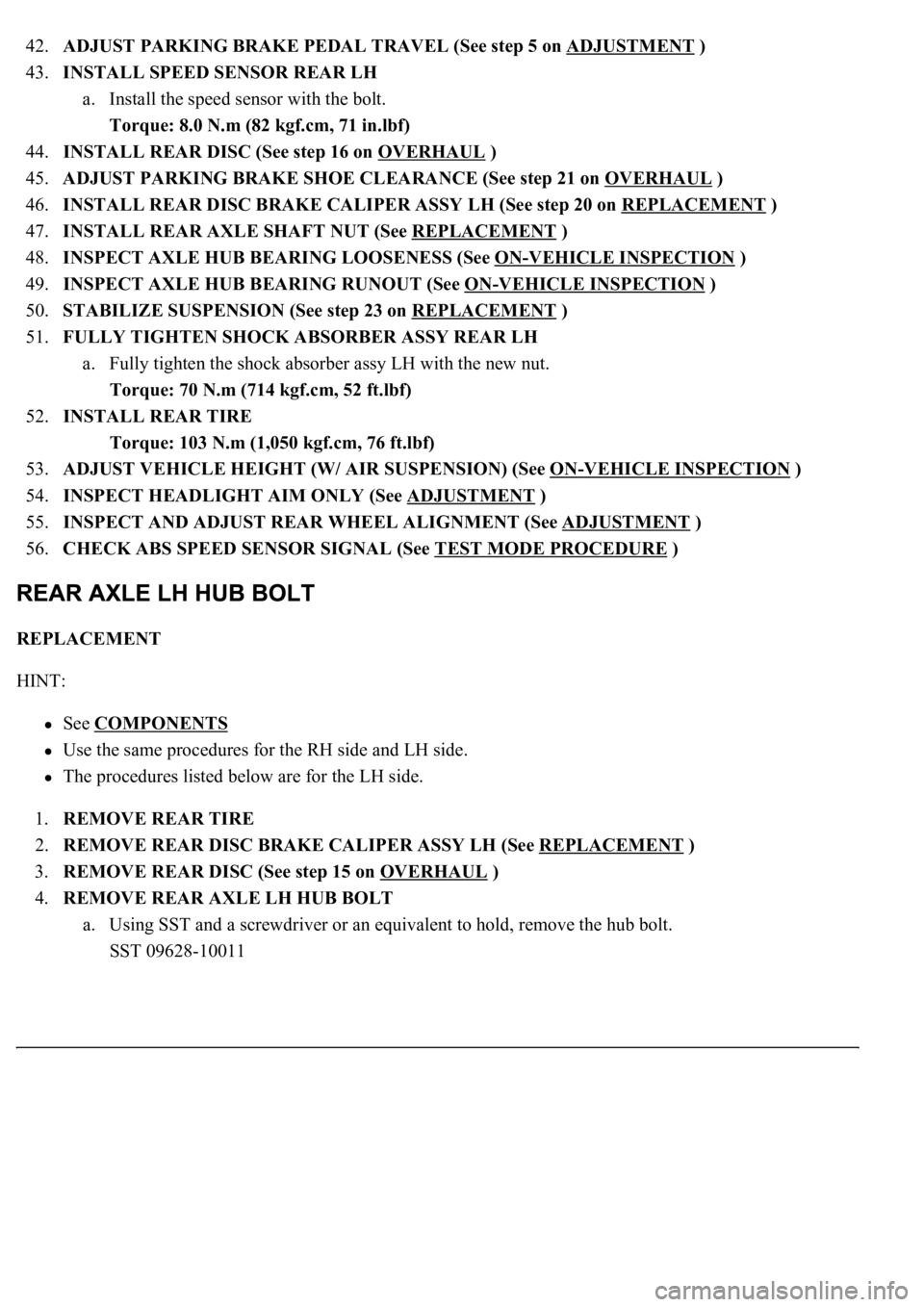
42.ADJUST PARKING BRAKE PEDAL TRAVEL (See step 5 on ADJUSTMENT )
43.INSTALL SPEED SENSOR REAR LH
a. Install the speed sensor with the bolt.
Torque: 8.0 N.m (82 kgf.cm, 71 in.lbf)
44.INSTALL REAR DISC (See step 16 on OVERHAUL
)
45.ADJUST PARKING BRAKE SHOE CLEARANCE (See step 21 on OVERHAUL
)
46.INSTALL REAR DISC BRAKE CALIPER ASSY LH (See step 20 on REPLACEMENT
)
47.INSTALL REAR AXLE SHAFT NUT (See REPLACEMENT
)
48.INSPECT AXLE HUB BEARING LOOSENESS (See ON
-VEHICLE INSPECTION )
49.INSPECT AXLE HUB BEARING RUNOUT (See ON
-VEHICLE INSPECTION )
50.STABILIZE SUSPENSION (See step 23 on REPLACEMENT
)
51.FULLY TIGHTEN SHOCK ABSORBER ASSY REAR LH
a. Fully tighten the shock absorber assy LH with the new nut.
Torque: 70 N.m (714 kgf.cm, 52 ft.lbf)
52.INSTALL REAR TIRE
Torque: 103 N.m (1,050 kgf.cm, 76 ft.lbf)
53.ADJUST VEHICLE HEIGHT (W/ AIR SUSPENSION) (See ON
-VEHICLE INSPECTION )
54.INSPECT HEADLIGHT AIM ONLY (See ADJUSTMENT
)
55.INSPECT AND ADJUST REAR WHEEL ALIGNMENT (See ADJUSTMENT
)
56.CHECK ABS SPEED SENSOR SIGNAL (See TEST MODE PROCEDURE
)
REPLACEMENT
HINT:
See COMPONENTS
Use the same procedures for the RH side and LH side.
The procedures listed below are for the LH side.
1.REMOVE REAR TIRE
2.REMOVE REAR DISC BRAKE CALIPER ASSY LH (See REPLACEMENT
)
3.REMOVE REAR DISC (See step 15 on OVERHAUL
)
4.REMOVE REAR AXLE LH HUB BOLT
a. Using SST and a screwdriver or an equivalent to hold, remove the hub bolt.
SST 09628-10011
Page 2410 of 4500
Fig. 102: Installing Rear Axle LH Hub Bolt
Courtesy of TOYOTA MOTOR SALES, U.S.A., INC.
6.INSTALL REAR DISC (See step 16 on OVERHAUL
)
7.ADJUST PARKING BRAKE SHOE CLEARANCE (See step 21 on OVERHAUL
)
8.INSTALL REAR DISC BRAKE CALIPER ASSY LH (See REPLACEMENT
)
9.INSTALL REAR TIRE
Page 2475 of 4500

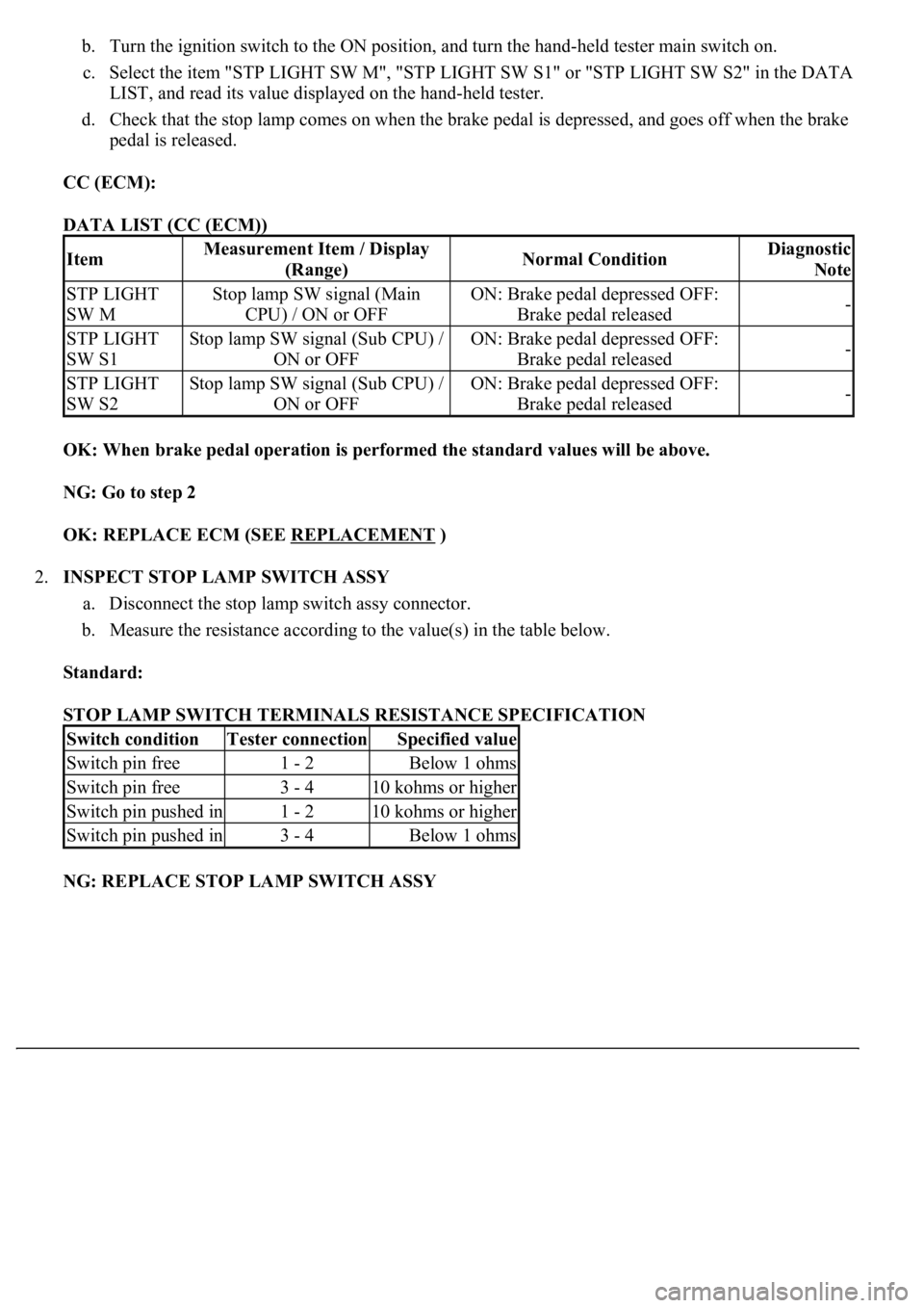
b. Turn the ignition switch to the ON position, and turn the hand-held tester main switch on.
c. Select the item "STP LIGHT SW M", "STP LIGHT SW S1" or "STP LIGHT SW S2" in the DATA
LIST, and read its value displayed on the hand-held tester.
d. Check that the stop lamp comes on when the brake pedal is depressed, and goes off when the brake
pedal is released.
CC (ECM):
DATA LIST (CC (ECM))
OK: When brake pedal operation is performed the standard values will be above.
NG: Go to step 2
OK: REPLACE ECM (SEE REPLACEMENT
)
2.INSPECT STOP LAMP SWITCH ASSY
a. Disconnect the stop lamp switch assy connector.
b. Measure the resistance according to the value(s) in the table below.
Standard:
STOP LAMP SWITCH TERMINALS RESISTANCE SPECIFICATION
NG: REPLACE STOP LAMP SWITCH ASSY
ItemMeasurement Item / Display
(Range)Normal ConditionDiagnostic
Note
STP LIGHT
SW MStop lamp SW signal (Main
CPU) / ON or OFFON: Brake pedal depressed OFF:
Brake pedal released-
STP LIGHT
SW S1Stop lamp SW signal (Sub CPU) /
ON or OFFON: Brake pedal depressed OFF:
Brake pedal released-
STP LIGHT
SW S2Stop lamp SW signal (Sub CPU) /
ON or OFFON: Brake pedal depressed OFF:
Brake pedal released-
Switch conditionTester connectionSpecified value
Switch pin free1 - 2Below 1 ohms
Switch pin free3 - 410 kohms or higher
Switch pin pushed in1 - 210 kohms or higher
Switch pin pushed in3 - 4Below 1 ohms
Page 2480 of 4500
Courtesy of TOYOTA MOTOR SALES, U.S.A., INC.
A: REPLACE ECM (SEE REPLACEMENT
)
5.INSPECT DRIVER SIDE J/B
a. Measure the voltage according to the value(s) in the table below.
Fig. 48: Identifying Driver Side Junction Block ECU Connector Terminals
Courtesy of TOYOTA MOTOR SALES, U.S.A., INC.
Standard:
ECU CONNECTOR VOLTAGE RESISTANCE SPECIFICATION
NG: Go to step 6
Pedal conditionTester connectionSpecification
DepressedD3-12 (STPO) - Body ground10 to 14 V
ReleasedD3-12 (STPO) - Body groundBelow 1 V
Page 2482 of 4500

OK: REPLACE DRIVER SIDE J/B
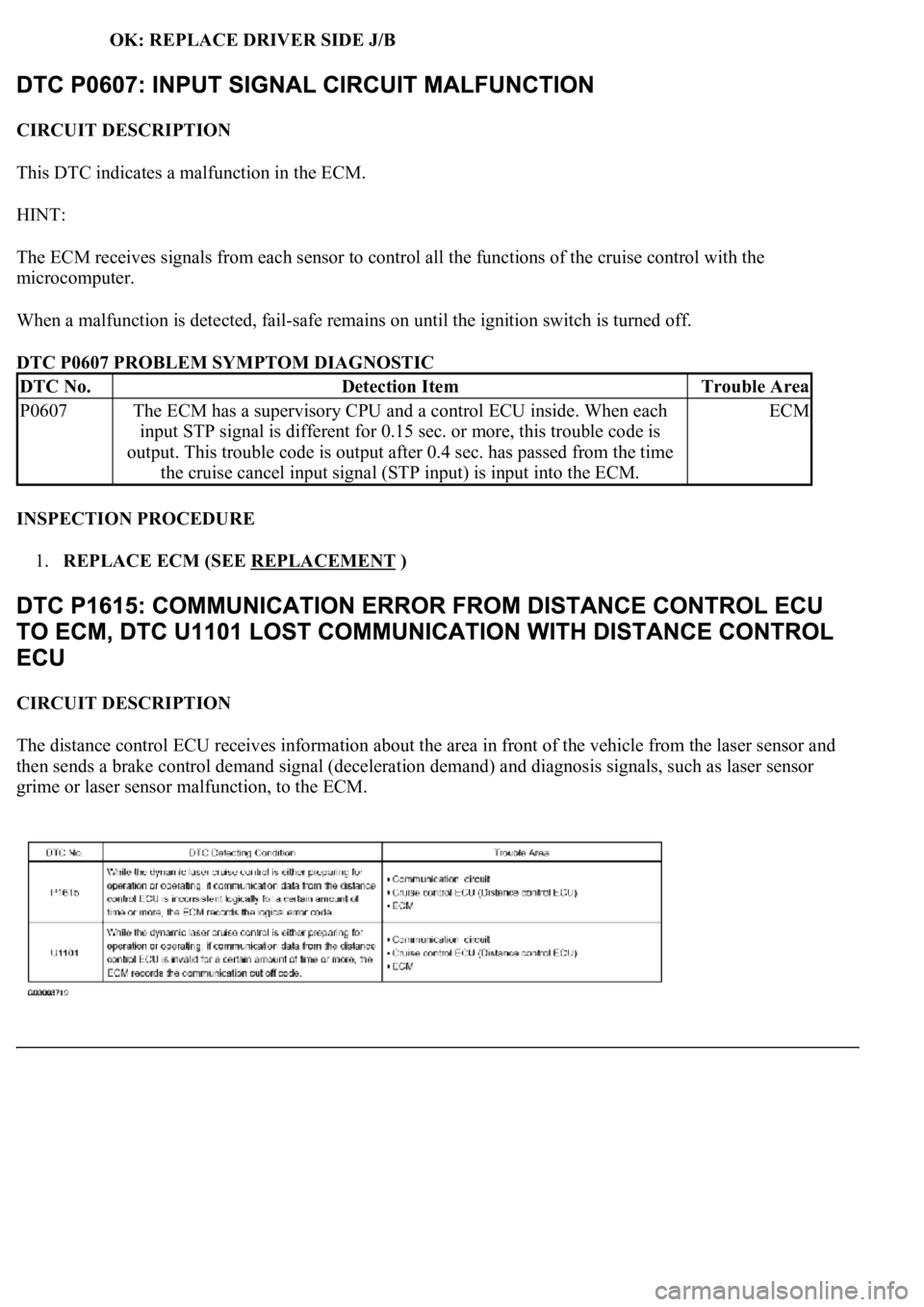
CIRCUIT DESCRIPTION
This DTC indicates a malfunction in the ECM.
HINT:
The ECM receives signals from each sensor to control all the functions of the cruise control with the
microcomputer.
When a malfunction is detected, fail-safe remains on until the ignition switch is turned off.
DTC P0607 PROBLEM SYMPTOM DIAGNOSTIC
INSPECTION PROCEDURE
1.REPLACE ECM (SEE REPLACEMENT
)
CIRCUIT DESCRIPTION
The distance control ECU receives information about the area in front of the vehicle from the laser sensor and
then sends a brake control demand signal (deceleration demand) and diagnosis signals, such as laser sensor
grime or laser sensor malfunction, to the ECM.
DTC No.Detection ItemTrouble Area
P0607The ECM has a supervisory CPU and a control ECU inside. When each
input STP signal is different for 0.15 sec. or more, this trouble code is
output. This trouble code is output after 0.4 sec. has passed from the time
the cruise cancel input signal (STP input) is input into the ECM.ECM
Page 2485 of 4500

NG: REPLACE CRUISE CONTROL ECU ASSY (SEE REPLACEMENT )
OK: SYSTEM OK
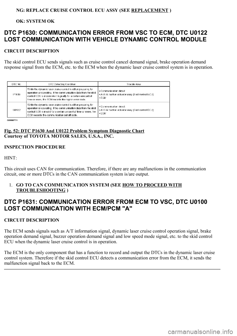
CIRCUIT DESCRIPTION
The skid control ECU sends signals such as cruise control cancel demand signal, brake operation demand
response signal from the ECM, etc. to the ECM when the dynamic laser cruise control system is in operation.
Fig. 52: DTC P1630 And U0122 Problem Symptom Diagnostic Chart
Courtesy of TOYOTA MOTOR SALES, U.S.A., INC.
INSPECTION PROCEDURE
HINT:
This circuit uses CAN for communication. Therefore, if there are any malfunctions in the communication
circuit, one or more DTCs in the CAN communication system is/are output.
1.GO TO CAN COMMUNICATION SYSTEM (SEE HOW TO PROCEED WITH
TROUBLESHOOTING )
CIRCUIT DESCRIPTION
The ECM sends signals such as A/T information signal, dynamic laser cruise control operation signal, brake
operation demand signal, buzzer operation demand signal and low speed mode signal, etc. to the skid control
ECU when the dynamic laser cruise control is in operation.
<0037004b004800030028002600300003004c005600030057004b0048000300520051004f005c000300460052005000530052005100480051005700030057004b004400570003004b0044005600030044000300490058005100460057004c00520051000300
57005200030055004800460052005500470003004400510047[ output the DTCs in the dynamic laser cruise
control system. Therefore if the skid control ECU detects a communication error from the ECM, it sends the
malfunction signal back to the ECM.
Page 2491 of 4500
Fig. 59: Identifying Laser Sensor Terminals
Courtesy of TOYOTA MOTOR SALES, U.S.A., INC.
c. Check the signal waveform between terminal LRDD (L1-3) of the laser sensor and body ground.
OK:
A waveform similar to that in the illustration to the left is output.
HINT:
Gauge set: 1 V/DIV, 2 ms/DIV
Condition: Ignition switch ON
NG: REPLACE LASER SENSOR (SEE REPLACEMENT
)
Page 2492 of 4500
Fig. 60: Signal Waveform Graph
Courtesy of TOYOTA MOTOR SALES, U.S.A., INC.
OK: REPLACE CRUISE CONTROL ECU ASSY (SEE REPLACEMENT
)
CIRCUIT DESCRIPTION
The laser sensor and cruise control ECU (distance control ECU) transmit the data for general vehicle control
and diagnosis function along the communication line.
The cruise control ECU (distance control ECU) determines the presumed R information based on the signal
from the steering wheel and yaw rate sensor.
The cruise control ECU (distance control ECU) transmits the current vehicle speed and presumed R information
to the laser sensor.