Page 165 of 4500

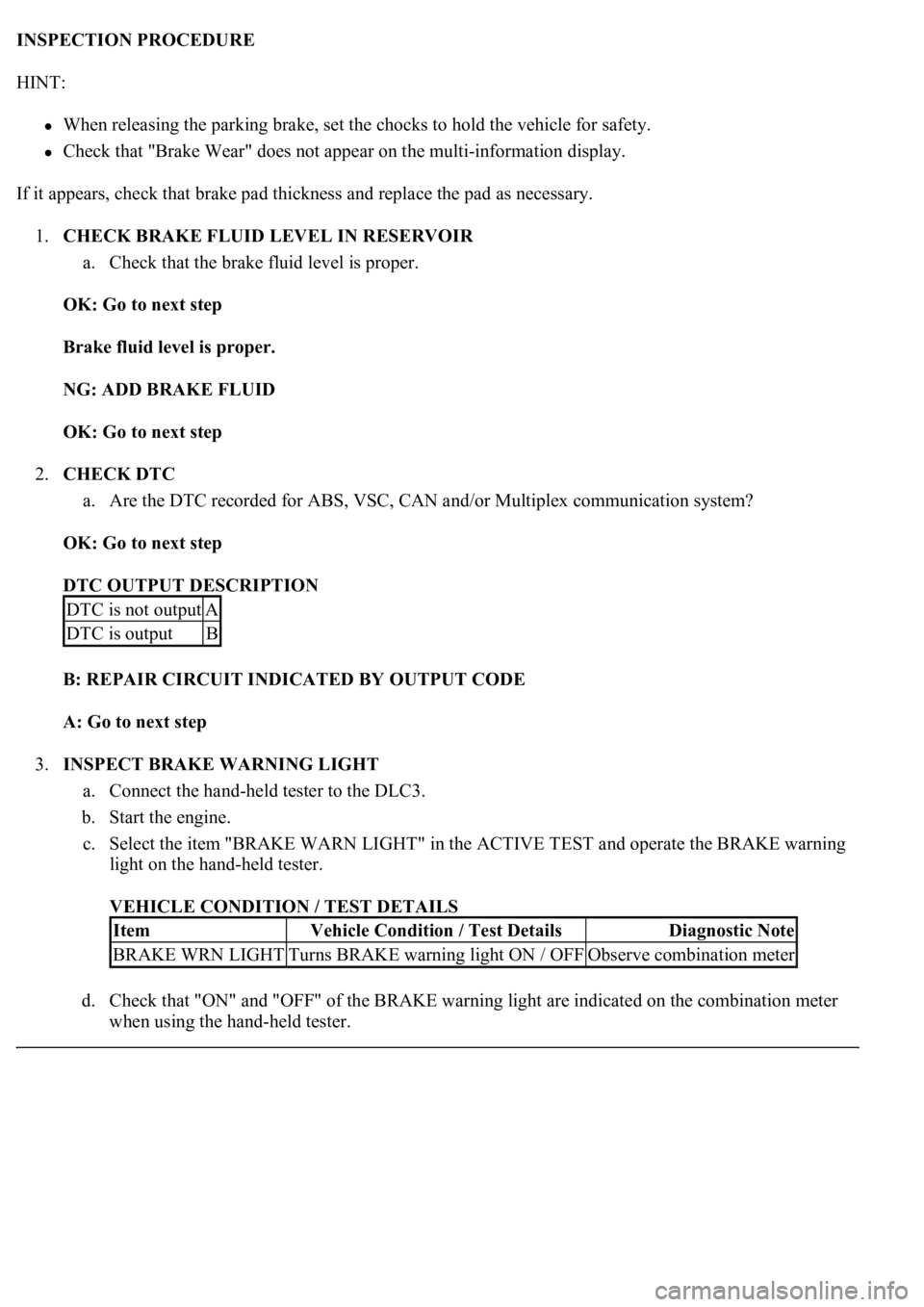
INSPECTION PROCEDURE
HINT:
When releasing the parking brake, set the chocks to hold the vehicle for safety.
Check that "Brake Wear" does not appear on the multi-information display.
If it appears, check that brake pad thickness and replace the pad as necessary.
1.CHECK BRAKE FLUID LEVEL IN RESERVOIR
a. Check that the brake fluid level is proper.
OK: Go to next step
Brake fluid level is proper.
NG: ADD BRAKE FLUID
OK: Go to next step
2.CHECK DTC
a. Are the DTC recorded for ABS, VSC, CAN and/or Multiplex communication system?
OK: Go to next step
DTC OUTPUT DESCRIPTION
B: REPAIR CIRCUIT INDICATED BY OUTPUT CODE
A: Go to next step
3.INSPECT BRAKE WARNING LIGHT
a. Connect the hand-held tester to the DLC3.
b. Start the engine.
c. Select the item "BRAKE WARN LIGHT" in the ACTIVE TEST and operate the BRAKE warning
light on the hand-held tester.
VEHICLE CONDITION / TEST DETAILS
d. Check that "ON" and "OFF" of the BRAKE warning light are indicated on the combination meter
when usin
g the hand-held tester.
DTC is not outputA
DTC is outputB
ItemVehicle Condition / Test DetailsDiagnostic Note
BRAKE WRN LIGHTTurns BRAKE warning light ON / OFFObserve combination meter
Page 184 of 4500
B: REPAIR CAN COMMUNICATION SYSTEM (SEE PRECAUTION )
A: Go to next step
4.INSPECT COMBINATION METER ASSEMBLY (SLIP INDICATOR LIGHT) (SEE PROBLEM
SYMPTOMS TABLE )
NG: REPAIR OR REPLACE COMBINATION METER ASSEMBLY
OK: REPLACE ABS & TRACTION ACTUATOR ASSY (SEE REPLACEMENT
)
CIRCUIT DESCRIPTION
The skid control buzzer sounds and VSC warning (Multi-information display) comes ON during VSC
operation.
WIRING DIAGRAM
DTC is outputB
Page 189 of 4500
Standard:
TESTER CONNECTION SPECIFIED CONDITION
NG: REPAIR OR REPLACE HARNESS OR CONNECTOR
OK: REPLACE ABS & TRACTION ACTUATOR ASSY (SEE REPLACEMENT
)
CIRCUIT DESCRIPTION
Connecting terminals TC and CG of the DLC3 causes the ECU to display the DTC by blinking the ABS
warning light.
WIRING DIAGRAM
Tester ConnectionSpecified Condition
S42-30 (BZ) - Body ground1 Mohms or higher
Page 210 of 4500

Fig. 6: Air Conditioning System Diagram (2 Of 2)
Courtesy of TOYOTA MOTOR SALES, U.S.A., INC.
1.GENERAL
a. The air conditioning system has the following features:
In compliance with the temperature set at the temperature control switch, the neural network
control calculates the outlet temperature based on the input signals from various sensors. In
addition, corrections in accordance with the signals from the evaporative temperature sensor
and the water temperature sensor are added to control the outlet air temperature.
Controls the front and rear blower motors in accordance with the airflow volume that has
been calculated by the neural network control based on the input signals from various
sensors.
Automatically switches the outlets in accordance with the outlet mode ratio that has been
calculated by the neural network control based on the input signals from various sensors.
Automatically controls the air inlet control damper in accordance with the airflow volume
that has been calculated by the neural network control.
Turns the compressor on/off and controls the discharge capacity based on the signals from
various sensors.
Based on the signals from the ambient temperature sensor, this control calculates the outside
temperature, which is then corrected in the air conditioner ECU, and shown in the multi-
information display in the combination meter.
Switched the rear defogger and outside rear view mirror heaters on for 15 minutes when the
rear defogger switch is switched on. Switched them off if the switch is pressed while they are
operating.
Controls the orientation and the angle of the front center register based on the input signals
from various sensors and on the outlet mode.
Determines whether the clean air filter (for the front A/C) is clogged by monitoring the air
inlets, and airflow volume.
The A/C amplifier automatically controls the air inlets based on the signals from the smog
ventilation sensor.
Improves the air quality by linking the air inlet control damper and the blower motor (for the
rear A/C and air purifier), based on the signals from the exhaust gas sensor and the smoke
sensor.
Checks the sensors in accordance with operation of the air conditioner switches.
2.MODEL POSITION AND DAMPER OPERATION
Page 217 of 4500

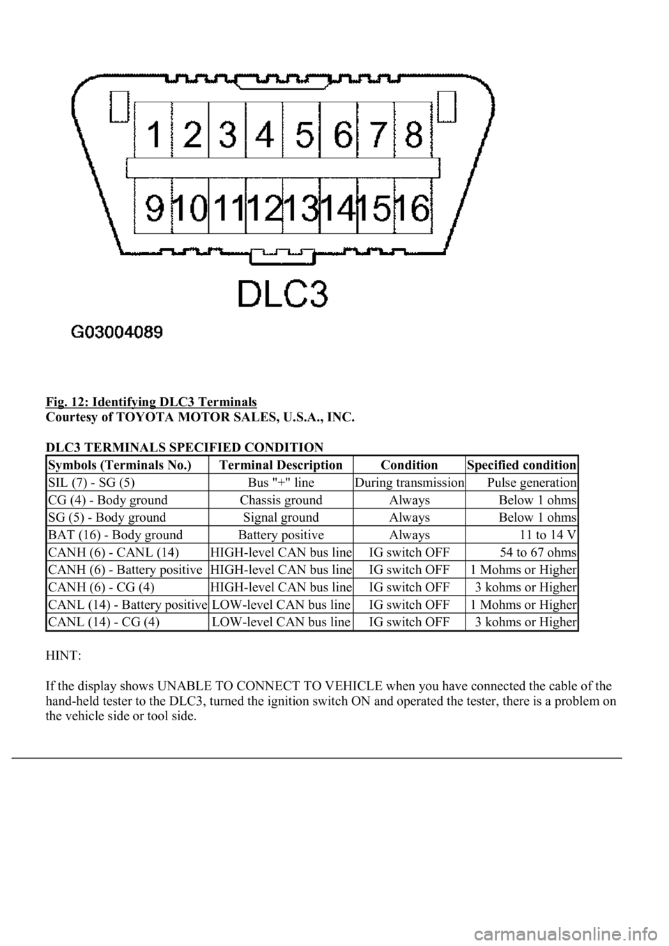
Fig. 12: Identifying DLC3 Terminals
Courtesy of TOYOTA MOTOR SALES, U.S.A., INC.
DLC3 TERMINALS SPECIFIED CONDITION
HINT:
If the display shows UNABLE TO CONNECT TO VEHICLE when you have connected the cable of the
hand-held tester to the DLC3, turned the ignition switch ON and operated the tester, there is a problem on
the vehicle side or tool side.
Symbols (Terminals No.)Terminal DescriptionConditionSpecified condition
SIL (7) - SG (5)Bus "+" lineDuring transmissionPulse generation
CG (4) - Body groundChassis groundAlwaysBelow 1 ohms
SG (5) - Body groundSignal groundAlwaysBelow 1 ohms
BAT (16) - Body groundBattery positiveAlways11 to 14 V
CANH (6) - CANL (14)HIGH-level CAN bus lineIG switch OFF54 to 67 ohms
CANH (6) - Battery positiveHIGH-level CAN bus lineIG switch OFF1 Mohms or Higher
CANH (6) - CG (4)HIGH-level CAN bus lineIG switch OFF3 kohms or Higher
CANL (14) - Battery positiveLOW-level CAN bus lineIG switch OFF1 Mohms or Higher
CANL (14) - CG (4)LOW-level CAN bus lineIG switch OFF3 kohms or Higher
Page 222 of 4500
Fig. 17: Identifying R/F Switch And Code Display (W/O Lexus Navigation System)
Courtesy of TOYOTA MOTOR SALES, U.S.A., INC.
If a slower display is desired, press the driver temperature up switch and change the display in the STEP
operation. Each time the driver temperature up switch is pressed, the display changes by 1 STEP.
Page 223 of 4500
Fig. 18: Identifying R/F Switch And Code Display (W/ Lexus Navigation System)
Courtesy of TOYOTA MOTOR SALES, U.S.A., INC.
HINT:
<0037004b0048000300450058005d005d0048005500030056005200580051004700560003005a004b0048005100030057004b004800030047004c00560053004f0044005c00480047000300570055005200580045004f004800030046005200470048000300
46004b00440051004a00480056001100030003[
Codes are displayed from the smaller to the larger numbers in order.
To cancel the check mode, press the "OFF" switch.
Page 226 of 4500
Fig. 21: Display Code - Conditions Chart
Courtesy of TOYOTA MOTOR SALES, U.S.A., INC.
1.DATA LIST
HINT:
From the DATA LIST displayed on the hand-held tester, you can read the values of the displays, sensors,
actuators and so on without parts removal. Reading the DATA LIST as the first STEP of troubleshooting
is one way to shorten labor time.
a. Connect the hand-held tester to the DLC3.
b. Turn the ignition switch to the ON position.
c. From the display on the tester, select the "DATA LIST".
DATA LIST / AIR CONDITIONER:
DATA LIST / AIR CONDITIONER
ItemMeasurement Item / Display
(Range)Normal ConditionDiagnostic
Note