Page 108 of 4500

When U0121/94, U0123/62, U0124/95 or U0126/63 are output together with C1231/31, inspect and
repair the trouble areas indicated by U0121/94, U0123/62, U0124/95 or U0126/63 first.
When the speed sensor or the yaw rate sensor has trouble, DTCs for the steering angle sensor may be
output even when the steering angle sensor is normal. When DTCs for the speed sensor or yaw rate
sensor are output together with other DTCs for the steering angle sensor, inspect and repair the speed
sensor and yaw rate sensor first, and then inspect and repair the steering angle sensor.
1.CHECK HARNESS AND CONNECTOR (MOMENTARY INTERRUPTION)
a. Using the hand-held tester, check for any momentary interruption in the wire harness and
connectors between the skid control ECU and steering angle sensor (see CHECK FOR
INTERMITTENT PROBLEMS ).
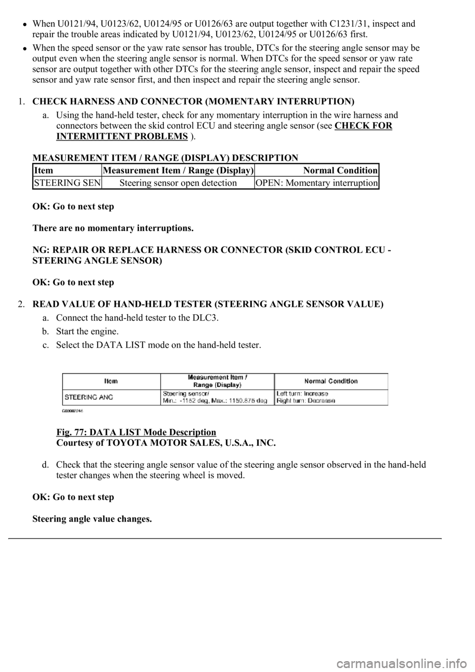
MEASUREMENT ITEM / RANGE (DISPLAY) DESCRIPTION
OK: Go to next step
There are no momentary interruptions.
NG: REPAIR OR REPLACE HARNESS OR CONNECTOR (SKID CONTROL ECU -
STEERING ANGLE SENSOR)
OK: Go to next step
2.READ VALUE OF HAND-HELD TESTER (STEERING ANGLE SENSOR VALUE)
a. Connect the hand-held tester to the DLC3.
b. Start the engine.
c. Select the DATA LIST mode on the hand-held tester.
Fig. 77: DATA LIST Mode Description
Courtesy of TOYOTA MOTOR SALES, U.S.A., INC.
d. Check that the steering angle sensor value of the steering angle sensor observed in the hand-held
tester changes when the steering wheel is moved.
OK: Go to next step
Steering angle value changes.
ItemMeasurement Item / Range (Display)Normal Condition
STEERING SENSteering sensor open detectionOPEN: Momentary interruption
Page 125 of 4500
OK: Go to next step
2.INSPECT BATTERY
a. Check the battery voltage.
Standard:
Voltage: 10 to 14 V
NG: INSPECT CHARGING SYSTEM (SEE ON
-VEHICLE INSPECTION )
OK: Go to next step
3.INSPECT SKID CONTROL ECU TERMINAL VOLTAGE (IG1 TERMINAL)
a. Connect the hand-held tester to the DLC3.
b. Start the engine.
c. Select the DATA LIST mode on the hand-held tester.
Fig. 91: DATA LIST Mode Description
Courtesy of TOYOTA MOTOR SALES, U.S.A., INC.
d. Read the voltage condition output from the ECU displayed on the hand-held tester.
Standard:
"Normal" is displayed.
NG: Go to step 4
OK: REPLACE ABS & TRACTION ACTUATOR ASSY (SEE REPLACEMENT
)
4.INSPECT SKID CONTROL ECU CONNECTOR (GND TERMINAL CONTINUITY)
a. Disconnect the skid control ECU connector.
b. Measure the resistance according to the value (s) in the table below.
Standard:
Page 128 of 4500

c. Select the DATA LIST mode on the hand-held tester.
MEASUREMENT ITEM / RANGE (DISPLAY) DESCRIPTION
d. Check that the brake fluid pressure value of the master cylinder pressure sensor observed in the
hand held tester changes when the brake pedal is depressed.
OK: Go to next step
When the pedal is depressed, displayed voltage on the hand-held tester increases.
NG: Go to step 2
OK: REPLACE ABS & TRACTION ACTUATOR ASSY (SEE REPLACEMENT
)
2.INSPECT SKID CONTROL ECU TERMINAL VOLTAGE (STP TERMINAL)
a. Disconnect the skid control ECU connector.
b. Measure the voltage according to the value (s) in the table below.
Standard:
TESTER CONNECTION SPECIFIED CONDITION
NG: CHECK AND REPLACE STOP LIGHT SWITCH CIRCUIT
OK: REPLACE ABS & TRACTION ACTUATOR ASSY (SEE REPLACEMENT
)
ItemMeasurement Item / Range (Display)Normal Condition
MAS CYL PRS
1Master cylinder pressure sensor 1 reading /
min.: 0 V, max.: 5 VWhen brake pedal is released:
0.3 to 0.9V
Tester ConnectionSwitch ConditionSpecified Condition
S42-27 (STP) - Body groundBrake pedal depressed8 to 14V
S42-27 (STP) - Body groundBrake pedal releasedBelow 1 V
Page 145 of 4500

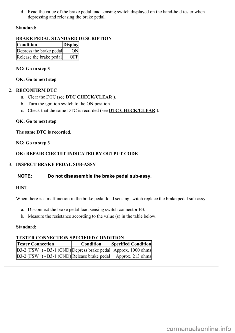
d. Read the value of the brake pedal load sensing switch displayed on the hand-held tester when
depressing and releasing the brake pedal.
Standard:
BRAKE PEDAL STANDARD DESCRIPTION
NG: Go to step 3
OK: Go to next step
2.RECONFIRM DTC
a. Clear the DTC (see DTC CHECK/CLEAR
).
b. Turn the ignition switch to the ON position.
c. Check that the same DTC is recorded (see DTC CHECK/CLEAR
).
OK: Go to next step
The same DTC is recorded.
NG: Go to step 3
OK: REPAIR CIRCUIT INDICATED BY OUTPUT CODE
3.INSPECT BRAKE PEDAL SUB-ASSY
HINT:
When there is a malfunction in the brake pedal load sensing switch replace the brake pedal sub-assy.
a. Disconnect the brake pedal load sensing switch connector B3.
b. Measure the resistance according to the value (s) in the table below.
Standard:
TESTER CONNECTION SPECIFIED CONDITION
ConditionDisplay
Depress the brake pedalON
Release the brake pedalOFF
Tester ConnectionConditionSpecified Condition
B3-2 (FSW+) - B3-1 (GND)Depress brake pedalApprox. 1000 ohms
B3-2 (FSW+) - B3-1 (GND)Release brake pedalApprox. 213 ohms
Page 151 of 4500
<0029004c004a00110003001400140016001d0003002c0057004800500003003000480044005600580055004800500048005100570003002c0057004800500003003500440051004a0048000300310052005500500044004f00030026005200510047004c00
57004c00520051[
Courtesy of TOYOTA MOTOR SALES, U.S.A., INC.
d. Read the voltage condition output from the ECU displayed on the hand-held tester.
OK: Go to next step
"Normal" is displayed.
NG: REPAIR OR REPLACE HARNESS OR CONNECTOR
OK: Go to next step
5.CHECK HARNESS AND CONNECTOR (SKID CONTROL ECU - BODY GROUND)
a. Disconnect the skid control ECU connector.
b. Measure the resistance according to the value (s) in the table below.
Standard:
TESTER CONNECTION SPECIFIED CONDITION
Tester ConnectionSpecified Condition
S42-32 (GND) - Body groundBelow 1 ohms
Page 158 of 4500
d. Check the voltage condition output from the ECU displayed on the hand-held tester.
OK: Go to next step
"Normal" is displayed.
NG: REPAIR OR REPLACE HARNESS OR CONNECTOR (IG CIRCUIT)
OK: Go to next step
5.CHECK HARNESS AND CONNECTOR (SKID CONTROL ECU - BODY GROUND)
a. Disconnect the skid control ECU connector.
b. Measure the resistance according to the value (s) in the table below.
Standard:
TESTER CONNECTION SPECIFIED CONDITION
NG: REPAIR OR REPLACE HARNESS OR CONNECTOR (GND CIRCUIT)
Tester ConnectionSpecified Condition
S42-32 (GND) - Body groundBelow 1 ohms
Page 161 of 4500

Result:
DTC OUTPUT DESCRIPTION
B: REPAIR CAN COMMUNICATION SYSTEM (SEE PRECAUTION
)
A: Go to next step
2.INSPECT MULTIPLEX COMMUNICATION SYSTEM
a. Is the DTC output for Multiplex communication system?
Result:
DTC OUTPUT DESCRIPTION
B: REPAIR MULTIPLEX COMMUNICATION SYSTEM (SEE DIAGNOSTIC TROUBLE
CODE CHART )
A: Go to next step
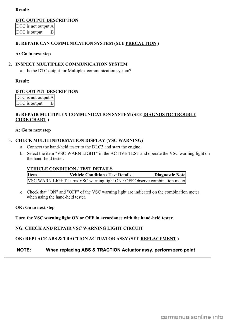
3.CHECK MULTI INFORMATION DISPLAY (VSC WARNING)
a. Connect the hand-held tester to the DLC3 and start the engine.
b. Select the item "VSC WARN LIGHT" in the ACTIVE TEST and operate the VSC warning light on
the hand-held tester.
VEHICLE CONDITION / TEST DETAILS
c. Check that "ON" and "OFF" of the VSC warning light are indicated on the combination meter
when using the hand-held tester.
OK: Go to next step
Turn the VSC warning light ON or OFF in accordance with the hand-held tester.
NG: CHECK AND REPAIR VSC WARNING LIGHT CIRCUIT
OK: REPLACE ABS & TRACTION ACTUATOR ASSY (SEE REPLACEMENT
)
DTC is not outputA
DTC is outputB
DTC is not outputA
DTC is outputB
ItemVehicle Condition / Test DetailsDiagnostic Note
VSC WARN LIGHTTurns VSC warning light ON / OFFObserve combination meter
Page 162 of 4500
CIRCUIT DESCRIPTION
The BRAKE warning light comes on when the brake fluid is insufficient, the parking brake is applied or the
EBD is defective.
The skid control ECU is connected to the combination meter via CAN and Multiplex communications.
The pad wear indicator is installed to the brake pad (right side).
If the wear indicator wire is open, "Brake Wear" appears on the multi-information display, which indicates that
the pad must be replaced.
WIRING DIAGRAM