Page 926 of 4500
COMPONENTS
Fig. 102: Identifying Floor Shift Assy Components (1 Of 3)
Courtesy of TOYOTA MOTOR SALES, U.S.A., INC.
Page 927 of 4500
Fig. 103: Identifying Floor Shift Assy Components (2 Of 3)
Courtesy of TOYOTA MOTOR SALES, U.S.A., INC.
Page 928 of 4500
Fig. 104: Identifying Floor Shift Assy Components (3 Of 3)
Courtesy of TOYOTA MOTOR SALES, U.S.A., INC.
Page 1022 of 4500
pedal reserve distance.
b. Depress the brake pedal and start the engine. If the pedal goes down slightly, operation is normal.
If not, replace the brake booster.
Fig. 55: Identifying Brake Pedal Operation Check
Courtesy of TOYOTA MOTOR SALES, U.S.A., INC.
2.AIR TIGHTNESS CHECK
a. Start the engine and stop it after 1 or 2 minutes. Depress the brake pedal several times slowly.
If the pedal can be depressed to the floor the first time, but on the 2nd or 3rd time cannot be
depressed as far, the booster is airtight.
If not, replace the brake booster.
b. Depress the brake pedal while the engine is running, and stop the engine with the pedal depressed.
If there is no change in the pedal reserve travel after the pedal is held for 30 seconds, the booster is
air tight.
If not, replace the brake booster.
Page 1023 of 4500
Fig. 56: Identifying Air Tightness Check
Courtesy of TOYOTA MOTOR SALES, U.S.A., INC.
3.INSPECT VACUUM CHECK VALVE
a. Check that there is ventilation from the booster to engine, and no ventilation from the engine to the
booster.
b.If any fault is found, replace the vacuum check valve.
Page 1049 of 4500
Fig. 81: Identifying Matchmarks On Front Disc And Axle Hub
Courtesy of TOYOTA MOTOR SALES, U.S.A., INC.
15.INSTALL FRONT DISC
a. Align the matchmarks, and install the front disc.
HINT:
When replacing the disc with a new one, select the installation position where the front disc has the
minimum runout.
16.INSPECT DISC RUNOUT
a. Ti
ghten the disc with the 3 hub nuts.
Page 1068 of 4500
Fig. 100: Identifying Matchmarks On Rear Disc And Axle Hub
Courtesy of TOYOTA MOTOR SALES, U.S.A., INC.
b. Release the parking brake, and remove the rear disc.
HINT:
If the disc cannot be removed easil
y, turn the shoe adjuster until the wheel turns freely.
Page 1108 of 4500

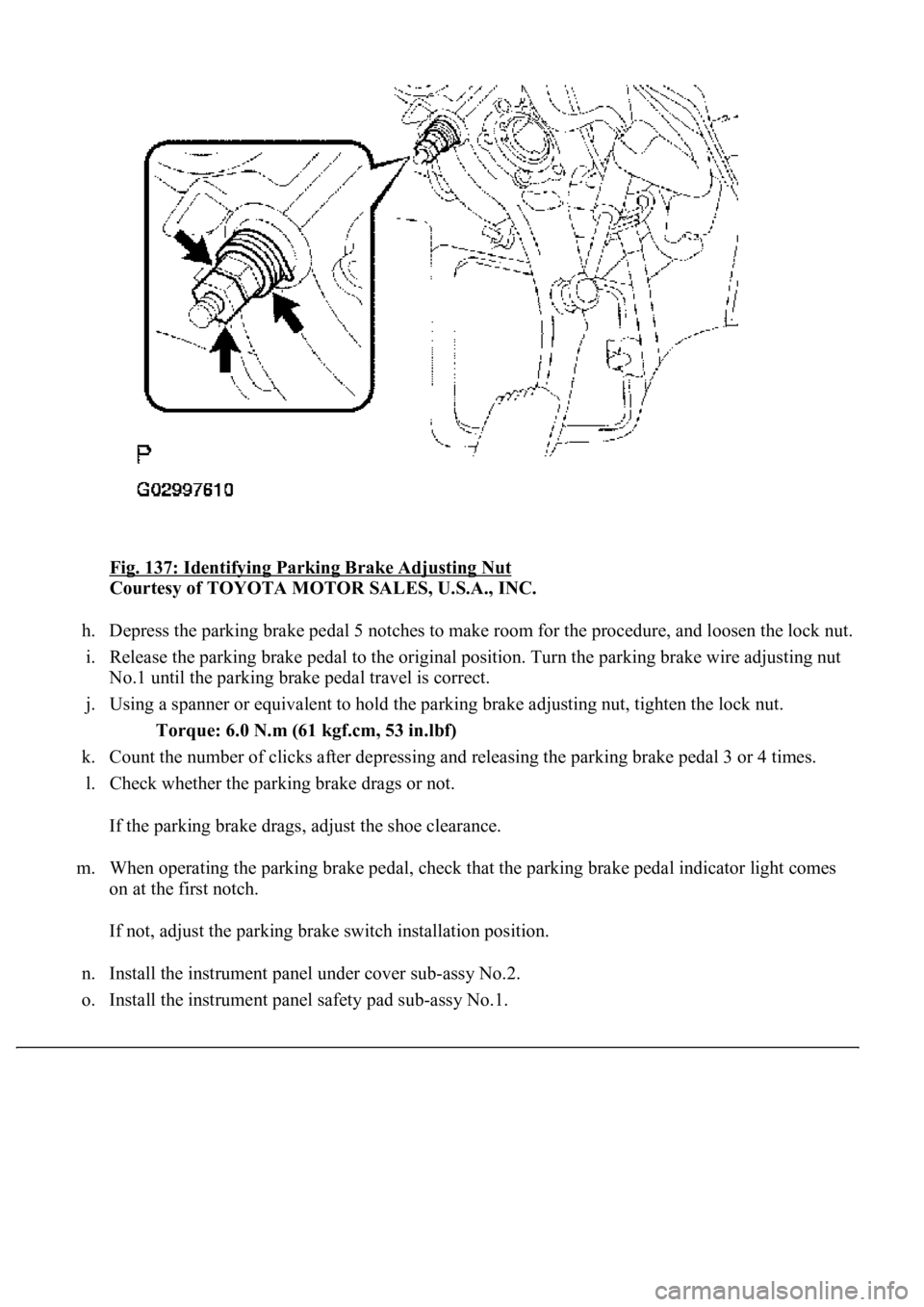
Fig. 137: Identifying Parking Brake Adjusting Nut
Courtesy of TOYOTA MOTOR SALES, U.S.A., INC.
h. Depress the parking brake pedal 5 notches to make room for the procedure, and loosen the lock nut.
i. Release the parking brake pedal to the original position. Turn the parking brake wire adjusting nut
<00310052001100140003005800510057004c004f00030057004b00480003005300440055004e004c0051004a0003004500550044004e004800030053004800470044004f000300570055004400590048004f0003004c005600030046005200550055004800
460057001100030003[
j. Using a spanner or equivalent to hold the parking brake adjusting nut, tighten the lock nut.
Torque: 6.0 N.m (61 kgf.cm, 53 in.lbf)
k. Count the number of clicks after depressing and releasing the parking brake pedal 3 or 4 times.
l. Check whether the parking brake drags or not.
If the parking brake drags, adjust the shoe clearance.
m. When operating the parking brake pedal, check that the parking brake pedal indicator light comes
on at the first notch.
If not, adjust the parking brake switch installation position.
n. Install the instrument panel under cover sub-assy No.2.
o. Install the instrument panel safet
y pad sub-assy No.1.