Page 816 of 4500
Fig. 98: Identifying Radio Receiver Assy - Stereo Component Tuner Connector
Courtesy of TOYOTA MOTOR SALES, U.S.A., INC.
TXM- - MTX-AlwaysBelow 1 ohms
TXM+ - Body groundAlways10 kohms or higher
TXM- - Body groundAlways10 kohms or higher
Page 817 of 4500
Fig. 99: Identifying Radio Receiver Assy - Stereo Component Tuner Connector
Courtesy of TOYOTA MOTOR SALES, U.S.A., INC.
NG: REPAIR OR REPLACE HARNESS OR CONNECTOR
OK: PROCEED TO NEXT CIRCUIT INSPECTION SHOWN IN DIAGNOSTIC TROUBLE
CODE CHART
Page 819 of 4500
Clean both sealing surfaces with a non-residue solvent.
Parts must be reassembled within 10 minutes of application. Otherwise, the packing (FIPG) material must
be removed and reapplied.
ADJUSTMENT
1.BEFORE TRANSMISSION FILL
This transmission requires Toyota Genuine ATF WS transmission fluid.
After servicing the transmission, you must refill the transmission with the correct amount of fluid.
Fig. 1: Identifying Transmission Case Cover Bolts
Courtesy of TOYOTA MOTOR SALES, U.S.A., INC.
Maintain the vehicle in a horizontal position while adjusting fluid level.
Proceed to step 2 if you replaced the transmission pan, drain plug, valve body and/or torque
converter.
Proceed to step 3 after removing the two bolts, transmission case cover and refill plug if you
replaced the transmission hose, output shaft oil seal and/or radiator.
Page 821 of 4500
Fig. 3: Identifying Overflow Plug
Courtesy of TOYOTA MOTOR SALES, U.S.A., INC.
2.TRANSMISSION PAN FILL
a. Remove the refill plug and overflow plug.
b. Fill the transmission through the refill hole until fluid begins to trickle out of the overflow tube.
c. Reinstall the overflow plug.
Fig. 4: Identifying Overflow Tube
Courtesy of TOYOTA MOTOR SALES, U.S.A., INC.
3.TRANSMISSION FILL
a. Fill the transmission with the correct amount of fluid as listed in the table below.
b. Reinstall the refill plug to avoid fluid splash.
TRANSMISSION FLUID REFERENCE
Performed RepairFill Amount
Radiator removal0.7 liters (0.74 US qts, 0.61 Imp. qts)
Transmission hose and pipe removal0.6 liters (0.63 US qts, 0.53 Imp. qts)
Page 823 of 4500

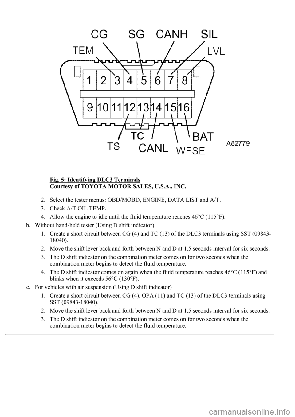
Fig. 5: Identifying DLC3 Terminals
Courtesy of TOYOTA MOTOR SALES, U.S.A., INC.
2. Select the tester menus: OBD/MOBD, ENGINE, DATA LIST and A/T.
3. Check A/T OIL TEMP.
4. Allow the engine to idle until the fluid temperature reaches 46°C (115°F).
b. Without hand-held tester (Using D shift indicator)
1. Create a short circuit between CG (4) and TC (13) of the DLC3 terminals using SST (09843-
18040).
2. Move the shift lever back and forth between N and D at 1.5 seconds interval for six seconds.
3. The D shift indicator on the combination meter comes on for two seconds when the
combination meter begins to detect the fluid temperature.
4. The D shift indicator comes on again when the fluid temperature reaches 46°C (115°F) and
blinks when it exceeds 56°C (130°F).
c. For vehicles with air suspension (Using D shift indicator)
1. Create a short circuit between CG (4), OPA (11) and TC (13) of the DLC3 terminals using
SST (09843-18040).
2. Move the shift lever back and forth between N and D at 1.5 seconds interval for six seconds.
3. The D shift indicator on the combination meter comes on for two seconds when the
combination meter begins to detect the fluid temperature.
Page 844 of 4500
Fig. 25: Identifying Automatic Transmission Assy Components
Courtesy of TOYOTA MOTOR SALES, U.S.A., INC.
REPLACEMENT
1.DISCONNECT BATTERY NEGATIVE TERMINAL
2.REMOVE ENGINE UNDER COVER NO.1
Page 923 of 4500
Fig. 99: Identifying Shift Lock Control Unit Assembly Connector Terminals
Courtesy of TOYOTA MOTOR SALES, U.S.A., INC.
Page 925 of 4500
Fig. 101: Identifying Shift Lock Control Unit Assembly Connector Terminals
Courtesy of TOYOTA MOTOR SALES, U.S.A., INC.
TERMINAL AND SPECIFIED VALUE<
TerminalMeasuring ConditionSpecified Value
4 (E) - Body groundConstantBelow 1 ohms