Page 628 of 4500
Fig. 146: Identifying Combination Meter Assy Connector Terminals
Courtesy of TOYOTA MOTOR SALES, U.S.A., INC.
NG: REPAIR OR REPLACE HARNESS OR CONNECTOR
OK:Go to next step
2.CHECK HARNESS AND CONNECTOR (SUSPENSION CONTROL ECU - BODY GROUND)
(SEE ELECTRONIC CIRCUIT INSPECTION PROCEDURE
)
a. Measure the resistance according to the value (s) in the table below.
TESTER CONNECTION STANDARD SPECIFIED CONDITION
Tester ConnectionSpecified Condition
C12-11 - Body groundBelow 1 ohms
Page 630 of 4500
Fig. 148: TD Terminal Wiring Diagram
Courtesy of TOYOTA MOTOR SALES, U.S.A., INC.
INSPECTION PROCEDURE
1.INSPECT DLC3 TERMINAL VOLTAGE (OPB TERMINAL)
a. Turn the ignition switch to the ON position.
b. Measure the voltage according to the value (s) in the table below.
TESTER CONNECTION STANDARD SPECIFIED CONDITION
NG: REPAIR OR REPLACE HARNESS OR CONNECTOR
Tester ConnectionSpecified Condition
D1-11 (OPB) - D1-4 (CG)10 to 14 V
D1-4 (CG) - Body groundBelow 1 ohms
Page 759 of 4500
a. Disconnect the radio receiver assy connector R2.
b. Measure the resistance according to the value (s) in the table below.
TESTER CONNECTION CONDITION CHART
c. Measure the voltage according to the value (s) in the table below.
Standard:
TESTER CONNECTION CONDITION CHART
NG: REPAIR OR REPLACE HARNESS OR CONNECTOR
OK: PROCEED TO NEXT CIRCUIT INSPECTION SHOWN IN PROBLEM SYMPTOMS
TABLE or DIAGNOSTIC TROUBLE CODE CHART
Tester connectionConditionSpecified condition
GND - Body groundAlwaysBelow 1 ohms
Tester connectionConditionSpecified condition
+B - GNDAlways10 to 14V
ACC - GNDIgnition SW ACC10 to 14V
Page 762 of 4500
c. Measure the voltage according to the value (s) in the table below.
TESTER CONNECTION CONDITION CHART
NG: REPAIR OR REPLACE HARNESS OR CONNECTOR
OK: PROCEED TO NEXT CIRCUIT INSPECTION SHOWN IN PROBLEM SYMPTOMS
TABLE or DIAGNOSTIC TROUBLE CODE CHART
Fig. 46: Inspecting Stereo Component Tuner
Courtesy of TOYOTA MOTOR SALES, U.S.A., INC.
CIRCUIT DESCRIPTION
This circuit provides the power to the stereo component amplifier ass
y.
Tester connectionConditionSpecified condition
B - GNDAlways10 to 14V
ACC - GNDIgnition SW ACC10 to 14V
Page 764 of 4500
c. Measure the voltage according to the value (s) in the table below.
TESTER CONNECTION CONDITION CHART
NG: REPAIR OR REPLACE HARNESS OR CONNECTOR
OK: PROCEED TO NEXT CIRCUIT INSPECTION SHOWN IN PROBLEM SYMPTOMS
TABLE or DIAGNOSTIC TROUBLE CODE CHART
Fig. 48: Disconnecting Stereo Component Amplifier Assy Connector S29, S30
Courtesy of TOYOTA MOTOR SALES, U.S.A., INC.
Tester connectionConditionSpecified condition
B+ ((1)),+B ((2)) - GNDAlways10 to 14V
B+ ((1)), +B2 ((2)) -GNDAlways10 to 14V
ACC - GNDIgnition SW ACC10 to 14V
(1)Mark Levinson models
(2)Standard models
Page 822 of 4500
HINT:
If you cannot add the listed amount of fluid, do the following:
1. Install the refill plug.
2. Allow the engine to idle with air conditioning OFF.
3. Move the shift lever through entire gear range to circulate fluid.
4. Wait for 30 seconds with the engine idling.
5. Stop the engine.
6. Remove the refill plug and add fluid.
7. Reinstall the refill plug.
4.FLUID CIRCULATION
a. Allow the engine to idle with the air conditioning OFF.
b. Move the shift lever through entire gear range to circulate fluid.
5.FLUID TEMPERATURE CHECK
a. With hand-held tester
1. Connect the han
d-held tester to the DLC3.
Output shaft oil seal replacement0.4 liters (0.42 US qts, 0.35 Imp. qts)
Transmission pan and drain plug removal1.3 liters (1.37 US qts, 1.14 Imp. qts)
Transmission valve body removal3.9 liters (4.12 US qts, 3.43 Imp. qts)
Torque converter replacement5.3 liters (5.60 US qts, 4.66 Imp. qts)
Entire transmission assembly7.2 liters (7.61 US qts, 6.34 Imp. qts)
Page 1223 of 4500

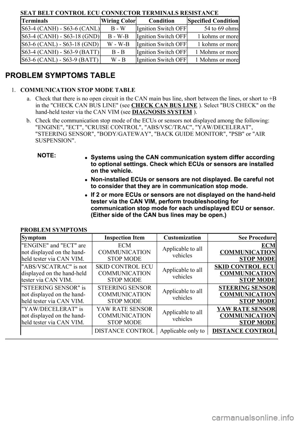
SEAT BELT CONTROL ECU CONNECTOR TERMINALS RESISTANCE
1.COMMUNICATION STOP MODE TABLE
a. Check that there is no open circuit in the CAN main bus line, short between the lines, or short to +B
in the "CHECK CAN BUS LINE" (see CHECK CAN BUS LINE
). Select "BUS CHECK" on the
hand-held tester via the CAN VIM (see DIAGNOSIS SYSTEM
).
b. Check the communication stop mode of the ECUs or sensors not displayed among the following:
"ENGINE", "ECT", "CRUISE CONTROL", "ABS/VSC/TRAC", "YAW/DECELERAT",
"STEERING SENSOR", "BODY/GATEWAY", "BACK GUIDE MONITOR", "PSB" or "AIR
SUSPENSION".
PROBLEM SYMPTOMS
TerminalsWiring ColorConditionSpecified Condition
S63-4 (CANH) - S63-6 (CANL)B - WIgnition Switch OFF54 to 69 ohms
S63-4 (CANH) - S63-18 (GND)B - W-BIgnition Switch OFF1 kohms or more
S63-6 (CANL) - S63-18 (GND)W - W-BIgnition Switch OFF1 kohms or more
S63-4 (CANH) - S63-9 (BATT)B - BIgnition Switch OFF1 Mohms or more
S63-6 (CANL) - S63-9 (BATT)W - BIgnition Switch OFF1 Mohms or more
SymptomInspection ItemCustomizationSee Procedure
"ENGINE" and "ECT" are
not displayed on the hand-
held tester via CAN VIM.ECM
COMMUNICATION
STOP MODEApplicable to all
vehiclesECM
COMMUNICATION
STOP MODE
"ABS/VSCATRAC" is not
displayed on the hand-held
tester via CAN VIM.SKID CONTROL ECU
COMMUNICATION
STOP MODEApplicable to all
vehiclesSKID CONTROL ECU
COMMUNICATION
STOP MODE
"STEERING SENSOR" is
not displayed on the hand-
held tester via CAN VIM.STEERING SENSOR
COMMUNICATION
STOP MODEApplicable to all
vehiclesSTEERING SENSOR
COMMUNICATION
STOP MODE
"YAW/DECELERAT" is
not displayed on the hand-
held tester via CAN VIM.YAW RATE SENSOR
COMMUNICATION
STOP MODEApplicable to all
vehiclesYAW RATE SENSOR
COMMUNICATION
STOP MODE
DISTANCE CONTROL Applicable only to DISTANCE CONTROL
Page 1231 of 4500
Dynamic
Radar/Laser
Cruise
(Maintains
vehicle-to-
vehicle
distance)
Tx
RxTx Rx Tx Rx
Vehicl
Vehi
dista
n
control
not op
e
Back
Monitor
(Exterior
view from
rear of
vehicle is
displayed
while
reversing)
Tx Rx Back m
onl
Air
Suspension
Control
(Controls
suspension
properly
based on
vehicle
conditions)
TxTx Rx Control
Meter
Display
(Displays
operation
condition
and DTCs)
TxTx RxTx
Lamp
not co
m
or remai
Pre -
collision
Safety (Skid
control ECU
brings BA in
standby
mode and
seat belt is
fastened by
seat belt
control ECU
when
distance
control ECU
determines
that collision
Rx Tx RxPre-col
l
safety sy
does
oper
a