Page 467 of 4500
Courtesy of TOYOTA MOTOR SALES, U.S.A., INC.
OK: REPLACE AIR CONDITIONING AMPLIFIER (SEE REPLACEMENT
)
Page 480 of 4500

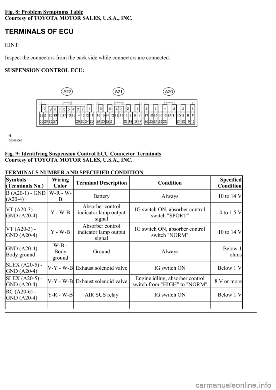
Fig. 8: Problem Symptoms Table
Courtesy of TOYOTA MOTOR SALES, U.S.A., INC.
HINT:
Inspect the connectors from the back side while connectors are connected.
SUSPENSION CONTROL ECU:
Fig. 9: Identifying Suspension Control ECU Connector Terminals
Courtesy of TOYOTA MOTOR SALES, U.S.A., INC.
TERMINALS NUMBER AND SPECIFIED CONDITION
Symbols
(Terminals No.)Wiring
ColorTerminal DescriptionConditionSpecified
Condition
B (A20-1) - GND
(A20-4)W-R - W-
BBatteryAlways10 to 14 V
VT (A20-3) -
GND (A20-4)Y - W-B
Absorber control
indicator lamp output
signalIG switch ON, absorber control
switch "SPORT"0 to 1.5 V
VT (A20-3) -
GND (A20-4)Y - W-B
Absorber control
indicator lamp output
signalIG switch ON, absorber control
switch "NORM"10 to 14 V
GND (A20-4) -
Body groundW-B -
Body
ground
GroundAlwaysBelow 1
ohms
SLEX (A20-5) -
GND (A20-4)V-Y - W-BExhaust solenoid valveIG switch ONBelow 1 V
SLEX (A20-5) -
GND (A20-4)V-Y - W-BExhaust solenoid valveEngine idling, absorber control
switch from "HIGH" to "NORM"8 V or more
RC (A20-6) -
GND (A20-4)Y-R - W-BAIR SUS relayIG switch ONBelow 1 V
Page 492 of 4500

a. Connect the hand-held tester to the DLC3.
b. Turn the ignition switch to the ON position.
c. Following the display on the hand-held tester, perform the "ACTIVE TEST".
VEHICLE CONDITION / TEST DETAILS
HINT:
If an abnormality is not found when the parts are inspected, inspect the suspension control ECU.
If a trouble code is displayed during the DTC check, check the circuit listed for that code.
DIAGNOSTIC TROUBLE CODE CHART
ItemVehicle Condition / Test DetailsDiagnostic Note
DAMPER FRChanges damper step (Front Right) / min.: 1
step, max.: 17 stepShock absorber hardens as
damper step increases
DAMPER FLChanges damper step (Front Left) / min.: 1
step, max.: 17 stepShock absorber hardens as
damper step increases
DAMPER RRChanges damper step (Rear Right) / min.: 1
step, max.: 17 stepShock absorber hardens as
damper step increases
DAMPER RLChanges damper step (Rear Left) / min.: 1 step,
max.: 17 stepShock absorber hardens as
damper step increases
FR UP &
DOWNRight front vehicle height / UP or DOWN-
FL UP & DOWNLeft front vehicle height / UP or DOWN-
RR UP &
DOWNRight rear vehicle height / UP or DOWN-
RL UP &
DOWNLeft rear vehicle height / UP or DOWN-
FR SOLTurn OFF right front solenoid valve one
second after turning it ONOperation of solenoid (clicking
sound) can be heard
FL SOLTurn OFF left front solenoid valve one second
after turning it ONOperation of solenoid (clicking
sound) can be heard
RR SOLTurn OFF right rear solenoid valve one second
after turning it ONOperation of solenoid (clicking
sound) can be heard
RL SOLTurn OFF left rear solenoid valve one second
after turning it ONOperation of solenoid (clicking
sound) can be heard
MOTOR
RELAYAIR SUS relay / ON or OFFOperation of solenoid (clicking
sound) can be heard
DTCDescription
DTC C1711, DTC C1712, DTC C1713,
DTC C1714, DTC C1714
RIGHT FRONT HEIGHT CONTROL SENSOR
CIRCUIT
Page 506 of 4500
Fig. 28: Identifying Height Control Sensor Sub-Assy Connector Terminals RH
Courtesy of TOYOTA MOTOR SALES, U.S.A., INC.
HEIGHT CONTROL SENSOR REAR LH: (C1714)
TESTER CONNECTION STANDARD SPECIFIED CONDITION
NG: REPAIR OR REPLACE HARNESS OR CONNECTOR
OK:Go to next step
Tester ConnectionSpecified Condition
A22-30 (SHRL) - H30-2 (SHRL)Below 1 ohms
A22-30 (SHRL) - Body ground10 Kohms or higher
Page 514 of 4500
Fig. 36: Identifying Height Control Sensor Sub-Assy Rear RH Connector Terminals
Courtesy of TOYOTA MOTOR SALES, U.S.A., INC.
TESTER CONNECTION STANDARD SPECIFIED CONDITION STANDARD (REAR LH)
NG: REPAIR OR REPLACE HARNESS OR CONNECTOR
Tester ConnectionSpecified Condition
A22-23 (SGL2) - H30-1 (SHG)Below 1 ohms
A22-24 (SBL2) - H30-3 (SHB)Below 1 ohms
A22-23 (SGL2) - Body ground10 Kohms or higher
A22-24 (SBL2) - Body ground10 Kohms or higher
Page 519 of 4500
Fig. 41: Identifying Height Control Sensor Rear RH Connector Terminals
Courtesy of TOYOTA MOTOR SALES, U.S.A., INC.
HEIGHT CONTROL SENSOR REAR LH: (C1714)
TESTER CONNECTION STANDARD SPECIFIED CONDITION
NG: REPAIR OR REPLACE HARNESS OR CONNECTOR
Tester ConnectionSpecified Condition
A22-30 (SHRL) - H30-2 (SHRL)Below 1 ohms
A22-30 (SHRL) - Body ground10 Kohms or higher
Page 526 of 4500
Fig. 48: Rear Acceleration Sensor Wiring Diagram
Courtesy of TOYOTA MOTOR SALES, U.S.A., INC.
INSPECTION PROCEDURE
1.READ VALUE ON HAND-HELD TESTER
a. Connect the hand-held tester to the DLC3.
b. Turn the ignition switch to the ON position and turn the hand-held tester main switch on.
c. Select the item below in the DATA LIST and read its value displayed on the hand-held tester.
DATA LIST AIR SUS
d. Check that the acceleration value of the acceleration sensor observed on the hand-held tester
changes when the vehicle is bounced.
Standard:
ItemNormal condition
G (UP & DOWN) FR (Right front acceleration sensor)0 +/- 31.9 mm/s2 at still condition
G (UP & DOWN) FL (Left front acceleration sensor)0 +/- 31.9 mm/s2 at still condition
G (UP & DOWN) R (Rear acceleration sensor)0 +/- 31.9 mm/s2 at still condition
Page 540 of 4500
Fig. 59: Identifying Absorber Control Actuator Rear LH Connector Terminals
Courtesy of TOYOTA MOTOR SALES, U.S.A., INC.
NG: REPLACE ABSORBER CONTROL ACTUATOR
OK:Go to next step
3.CHECK HARNESS AND CONNECTOR (ABSORBER CONTROL ACTUATOR - SUSPENSION
CONTROL ECU) (SEE ELECTRONIC CIRCUIT INSPECTION PROCEDURE
)
a. Disconnect the air suspension ECU A21 or A22 connector.
b. Measure the resistance according to the value (s) in the table below.
TESTER CONNECTION STANDARD SPECIFIED CONDITION STANDARD (FRONT RH)
Tester ConnectionSpecified Condition
A21-1 (FAR+) - S6-2 (FAR+)Below 1 ohms
A21-2 (FAR-) - S6-5 (FAR-)Below 1 ohms
A21-3 (FBR+) - S6-1 (FBR+)Below 1 ohms
A21-4 (FBR-) - S6-4 (FBR-)Below 1 ohms
A21-1 (FAR+) - Body ground10 Kohms or higher