Page 1880 of 4500
3.REMOVE AIR CLEANER INLET NO.1
4.DRAIN ENGINE COOLANT (See REPLACEMENT
)
5.REMOVE V-BANK COVER
6.REMOVE INTAKE AIR CONNECTOR PIPE
7.DISCONNECT RADIATOR HOSE NO.1
8.DISCONNECT RADIATOR HOSE NO.2
9.DISCONNECT OIL COOLER INLET TUBE NO.1
10.DISCONNECT OIL COOLER OUTLET TUBE NO.1
11.REMOVE AIR CLEANER ASSY
12.REMOVE RADIATOR AND FAN ASSEMBLY
a. Disconnect the cooling fan ECU connector.
b. Remove the 2 nuts and 2 radiator upper supports.
c. Remove the radiator and fan assembly.
d. Remove the 2 radiator lower supports.
Fig. 29: Removing Nuts And Radiator Upper Supports
Courtesy of TOYOTA MOTOR SALES, U.S.A., INC.
Page 1881 of 4500

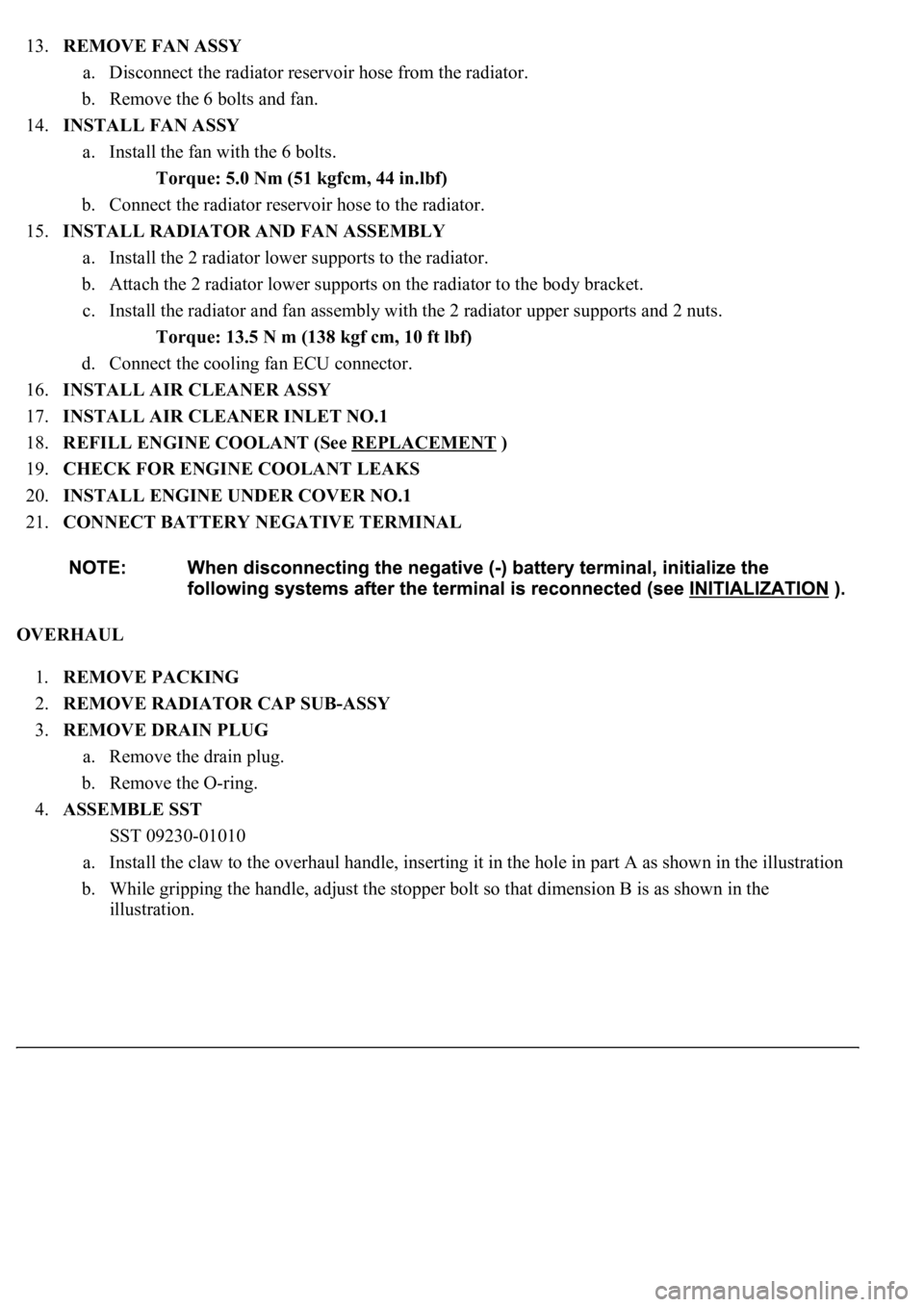
13.REMOVE FAN ASSY
a. Disconnect the radiator reservoir hose from the radiator.
b. Remove the 6 bolts and fan.
14.INSTALL FAN ASSY
a. Install the fan with the 6 bolts.
Torque: 5.0 Nm (51 kgfcm, 44 in.lbf)
b. Connect the radiator reservoir hose to the radiator.
15.INSTALL RADIATOR AND FAN ASSEMBLY
a. Install the 2 radiator lower supports to the radiator.
b. Attach the 2 radiator lower supports on the radiator to the body bracket.
c. Install the radiator and fan assembly with the 2 radiator upper supports and 2 nuts.
Torque: 13.5 N m (138 kgf cm, 10 ft lbf)
d. Connect the cooling fan ECU connector.
16.INSTALL AIR CLEANER ASSY
17.INSTALL AIR CLEANER INLET NO.1
18.REFILL ENGINE COOLANT (See REPLACEMENT
)
19.CHECK FOR ENGINE COOLANT LEAKS
20.INSTALL ENGINE UNDER COVER NO.1
21.CONNECT BATTERY NEGATIVE TERMINAL
OVERHAUL
1.REMOVE PACKING
2.REMOVE RADIATOR CAP SUB-ASSY
3.REMOVE DRAIN PLUG
a. Remove the drain plug.
b. Remove the O-ring.
4.ASSEMBLE SST
SST 09230-01010
a. Install the claw to the overhaul handle, inserting it in the hole in part A as shown in the illustration
b. While gripping the handle, adjust the stopper bolt so that dimension B is as shown in the
illustration.
Page 1898 of 4500
HINT:
The installation procedures are the removal procedures in reverse order. However, only installation procedures
requiring additional information are included.
1.DRAIN ENGINE COOLANT FROM RADIATOR (See REPLACEMENT
)
2.REMOVE AIR CLEANER INLET NO.1
3.REMOVE AIR CLEANER ASSY (See REPLACEMENT
)
4.DISCONNECT RADIATOR HOSE NO.1
5.REMOVE FAN ASSY
a. Disconnect the connector.
b. Remove the 6 bolts and fan.
6.REMOVE COOLING FAN ECU
a. Disconnect the 2 connectors.
b. Remove the 2 screws and ECU.
7.REMOVE FAN
a. Remove the 2 nuts and 2 fans.
8.REMOVE COOLING FAN MOTOR
a. Disconnect the 2 wires from the fan shroud.
b. Remove the 6 screws and 2 cooling fan motors.
Page 2015 of 4500
GENERAL MOTORS
GENERAL MOTORS - DOMESTIC LIGHT TRUCKS & VANS
ACURA
ACURA - IMPORTED CARS & TRUCKS
All OthersUnder Left Side Of Dash
1997-98
DieselUnder Left Side Of Dash
All OthersLeft Front Corner Of Engine Compartment
Villager (1993)On Left Side Of Engine Compartment, Below
Coolant Reservoir
ApplicationConnector Location
Astro & Safari Van (1986-87)Under Left Corner Of Cowl
"S" & "T" Series Blazer, Bravada, Envoy, Jimmy, Pickup & Sonoma
1982-85
1.9LUnder Left Side Of Dash, Behind ECM
2.0L & 2.8LUnder Ashtray
2.5LUnder Left Side Of Dash
1986-87Under Ashtray
Van ("G" Series) (1982-87)Under Driver's Seat
ApplicationConnector Location
Integra
1991-93Behind Right Kick Panel
1994-97Behind Glove Compartment
1998-02Behind Right Side Of Center Console
Legend
1991-93Under Right Side Of Dash, Above PGM-FI
ECU/PCM
1994-95Behind Glove Compartment
NSX (1997-01)Under Glove Compartment
Page 2632 of 4500

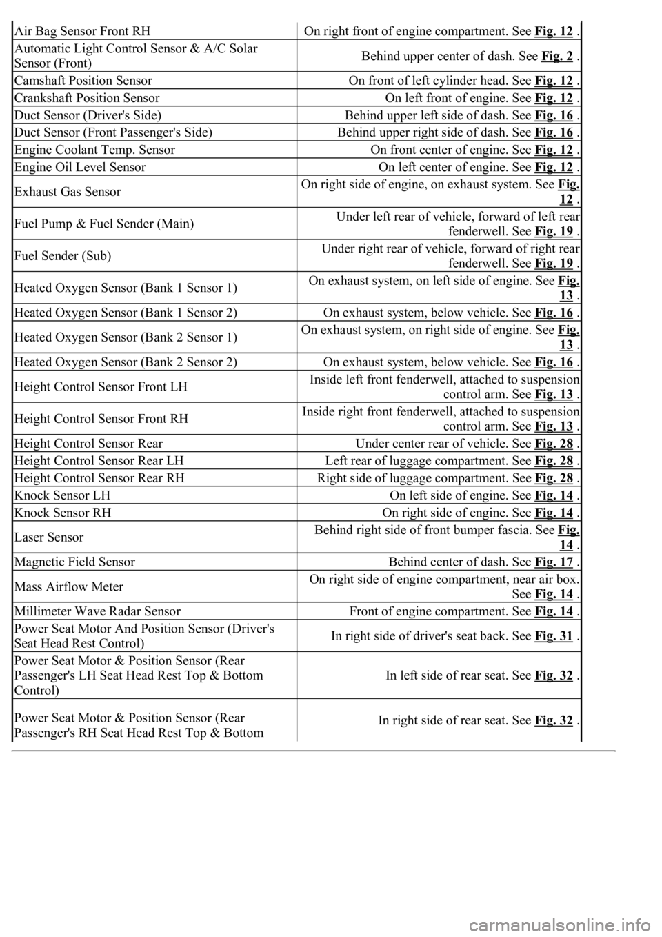
Air Bag Sensor Front RHOn right front of engine compartment. See Fig. 12 .
Automatic Light Control Sensor & A/C Solar
Sensor (Front)Behind upper center of dash. See Fig. 2 .
Camshaft Position SensorOn front of left cylinder head. See Fig. 12 .
Crankshaft Position SensorOn left front of engine. See Fig. 12 .
Duct Sensor (Driver's Side)Behind upper left side of dash. See Fig. 16 .
Duct Sensor (Front Passenger's Side)Behind upper right side of dash. See Fig. 16 .
Engine Coolant Temp. SensorOn front center of engine. See Fig. 12 .
Engine Oil Level SensorOn left center of engine. See Fig. 12 .
Exhaust Gas SensorOn right side of engine, on exhaust system. See Fig.
12 .
Fuel Pump & Fuel Sender (Main)Under left rear of vehicle, forward of left rear
fenderwell. See Fig. 19
.
Fuel Sender (Sub)Under right rear of vehicle, forward of right rear
fenderwell. See Fig. 19
.
Heated Oxygen Sensor (Bank 1 Sensor 1)On exhaust system, on left side of engine. See Fig.
13 .
Heated Oxygen Sensor (Bank 1 Sensor 2)On exhaust system, below vehicle. See Fig. 16 .
Heated Oxygen Sensor (Bank 2 Sensor 1)On exhaust system, on right side of engine. See Fig.
13 .
Heated Oxygen Sensor (Bank 2 Sensor 2)On exhaust system, below vehicle. See Fig. 16 .
Height Control Sensor Front LHInside left front fenderwell, attached to suspension
control arm. See Fig. 13
.
Height Control Sensor Front RHInside right front fenderwell, attached to suspension
control arm. See Fig. 13
.
Height Control Sensor RearUnder center rear of vehicle. See Fig. 28 .
Height Control Sensor Rear LHLeft rear of luggage compartment. See Fig. 28 .
Height Control Sensor Rear RHRight side of luggage compartment. See Fig. 28 .
Knock Sensor LHOn left side of engine. See Fig. 14 .
Knock Sensor RHOn right side of engine. See Fig. 14 .
Laser SensorBehind right side of front bumper fascia. See Fig.
14 .
Magnetic Field SensorBehind center of dash. See Fig. 17 .
Mass Airflow MeterOn right side of engine compartment, near air box.
See Fig. 14
.
Millimeter Wave Radar SensorFront of engine compartment. See Fig. 14 .
Power Seat Motor And Position Sensor (Driver's
Seat Head Rest Control)In right side of driver's seat back. See Fig. 31 .
Power Seat Motor & Position Sensor (Rear
Passenger's LH Seat Head Rest Top & Bottom
Control)
In left side of rear seat. See Fig. 32 .
Power Seat Motor & Position Sensor (Rear
Passenger's RH Seat Head Rest Top & Bottom In right side of rear seat. See Fig. 32 .
Page 2679 of 4500

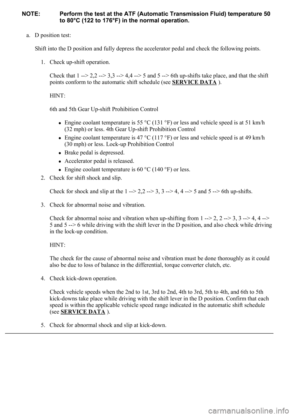
a. D position test:
Shift into the D position and fully depress the accelerator pedal and check the following points.
1. Check up-shift operation.
Check that 1 --> 2,2 --> 3,3 --> 4,4 --> 5 and 5 --> 6th up-shifts take place, and that the shift
points conform to the automatic shift schedule (see SERVICE DATA
).
HINT:
6th and 5th Gear Up-shift Prohibition Control
Engine coolant temperature is 55 °C (131 °F) or less and vehicle speed is at 51 km/h
(32 mph) or less. 4th Gear Up-shift Prohibition Control
Engine coolant temperature is 47 °C (117 °F) or less and vehicle speed is at 49 km/h
(30 mph) or less. Lock-up Prohibition Control
Brake pedal is depressed.
Accelerator pedal is released.
<00280051004a004c005100480003004600520052004f0044005100570003005700480050005300480055004400570058005500480003004c00560003001900130003008300260003000b001400170013000300830029000c0003005200550003004f004800
560056001100030003[
2. Check for shift shock and slip.
Check for shock and slip at the 1 --> 2,2 --> 3, 3 --> 4, 4 --> 5 and 5 --> 6th up-shifts.
3. Check for abnormal noise and vibration.
Check for abnormal noise and vibration when up-shifting from 1 --> 2, 2 --> 3, 3 --> 4, 4 -->
5 and 5 --> 6 while driving with the shift lever in the D position, and also check while driving
in the lock-up condition.
HINT:
The check for the cause of abnormal noise and vibration must be done thoroughly as it could
also be due to loss of balance in the differential, torque converter clutch, etc.
4. Check kick-down operation.
<0026004b00480046004e000300590048004b004c0046004f004800030056005300480048004700560003005a004b0048005100030057004b004800030015005100470003005700520003001400560057000f00030016005500470003005700520003001500
510047000f000300170057004b000300570052000300160055[d, 5th to 4th, and 6th to 5th
kick-downs take place while driving with the shift lever in the D position. Confirm that each
speed is within the applicable vehicle speed range indicated in the automatic shift schedule
(see SERVICE DATA
).
5. Check for abnormal shock and slip at kic
k-down.
Page 2695 of 4500

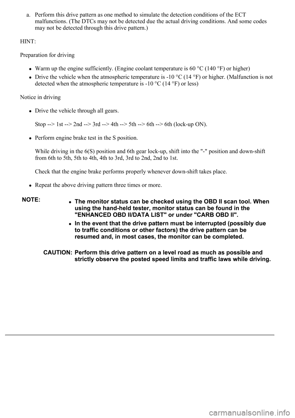
a. Perform this drive pattern as one method to simulate the detection conditions of the ECT
malfunctions. (The DTCs may not be detected due the actual driving conditions. And some codes
may not be detected through this drive pattern.)
HINT:
Preparation for driving
Warm up the engine sufficiently. (Engine coolant temperature is 60 °C (140 °F) or higher)
Drive the vehicle when the atmospheric temperature is -10 °C (14 °F) or higher. (Malfunction is not
detected when the atmospheric temperature is -10 °C (14 °F) or less)
Notice in driving
Drive the vehicle through all gears.
Stop --> 1st --> 2nd --> 3rd --> 4th --> 5th --> 6th --> 6th (lock-up ON).
Perform engine brake test in the S position.
While driving in the 6(S) position and 6th gear lock-up, shift into the "-" position and down-shift
<0049005500520050000300190057004b000300570052000300180057004b000f000300180057004b000300570052000300170057004b000f000300170057004b0003005700520003001600550047000f000300160055004700030057005200030015005100
47000f00030015005100470003005700520003001400560057[.
<0026004b00480046004e00030057004b0044005700030057004b0048000300480051004a004c005100480003004500550044004e00480003005300480055004900520055005000560003005300550052005300480055004f005c0003005a004b0048005100
48005900480055000300470052005a005100100056004b004c[ft takes place.
Repeat the above driving pattern three times or more.
Page 2712 of 4500
Fig. 34: Identifying DLC3 Terminals
Courtesy of TOYOTA MOTOR SALES, U.S.A., INC.
FREEZE FRAME DATA
Freeze frame data records the engine conditions (fuel system, calculated load, engine coolant temperature, fuel
trim, engine speed, vehicle speed, etc.) when a malfunction is detected. When troubleshooting, freeze frame
data can help determine if the vehicle was running or stopped, if the engine was warmed up or not, if the air/fuel
ratio was Lean or Rich, and other data from the time the malfunction occurred.
The hand-held tester records freeze frame data in five different instances: 1) 3 times before the DTC is set, 2)
once when the DTC is set, and 3) once after the DTC is set. These data can be used to simulate the vehicle's
condition around the time when the malfunction occurred. The data may help find the cause of the malfunction,
or
judge if the DTC is being caused by a temporary malfunction or not.