Page 1185 of 4500
Fig. 209: Installing Shoe Return Tension Spring
Courtesy of TOYOTA MOTOR SALES, U.S.A., INC.
19.CHECK PARKING BRAKE INSTALLATION
a. Make sure that all the parts are installed properly.
If not, reinstall the parts properly.
Page 1186 of 4500
Fig. 210: Checking Parking Brake Installation
Courtesy of TOYOTA MOTOR SALES, U.S.A., INC.
20.INSTALL REAR DISC
a. Align the matchmarks on the disc and rear axle hub.
Page 1187 of 4500
Fig. 211: Aligning Matchmarks On Disc And Rear Axle Hub
Courtesy of TOYOTA MOTOR SALES, U.S.A., INC.
21.ADJUST PARKING BRAKE SHOE CLEARANCE
a. Remove the hole plug.
b. Turn the shoe adjuster and expand the shoes until the disc locks.
c. Return the shoe adjuster 7 notches.
d. Install the hole plug.
Page 1190 of 4500
23.INSTALL REAR WHEEL
Torque: 103 N.m (1,050 kgf.cm, 76 ft.lbf)
24.SETTLING PARKING BRAKE SHOES AND DISC
a. Drive the vehicle at approximately 50 km/h (31 mph) on a safe, level and dry road.
b. Depress the parking brake pedal with a force of 150 N (15 kgf, 34 lbf).
c. Drive the vehicle for approximately 400 meters (0.25 mile) in this condition.
d. Repeat this procedure 2 or 3 times.
25.CHECK PARKING BRAKE PEDAL TRAVEL (SEE ADJUSTMENT
)
26.ADJUST PARKING BRAKE PEDAL TRAVEL (SEE ADJUSTMENT
)
Page 1744 of 4500

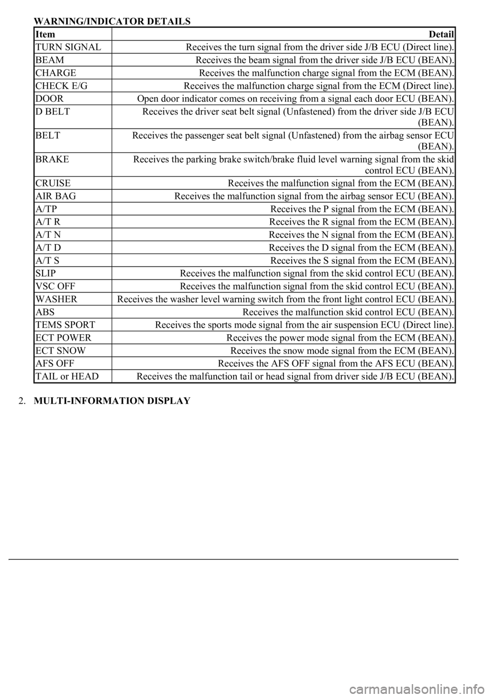
WARNING/INDICATOR DETAILS
2.MULTI-INFORMATION DISPLAY
ItemDetail
TURN SIGNALReceives the turn signal from the driver side J/B ECU (Direct line).
BEAMReceives the beam signal from the driver side J/B ECU (BEAN).
CHARGEReceives the malfunction charge signal from the ECM (BEAN).
CHECK E/GReceives the malfunction charge signal from the ECM (Direct line).
DOOROpen door indicator comes on receiving from a signal each door ECU (BEAN).
D BELTReceives the driver seat belt signal (Unfastened) from the driver side J/B ECU
(BEAN).
BELTReceives the passenger seat belt signal (Unfastened) from the airbag sensor ECU
(BEAN).
BRAKEReceives the parking brake switch/brake fluid level warning signal from the skid
control ECU (BEAN).
CRUISEReceives the malfunction signal from the ECM (BEAN).
AIR BAGReceives the malfunction signal from the airbag sensor ECU (BEAN).
A/TPReceives the P signal from the ECM (BEAN).
A/T RReceives the R signal from the ECM (BEAN).
A/T NReceives the N signal from the ECM (BEAN).
A/T DReceives the D signal from the ECM (BEAN).
A/T SReceives the S signal from the ECM (BEAN).
SLIPReceives the malfunction signal from the skid control ECU (BEAN).
VSC OFFReceives the malfunction signal from the skid control ECU (BEAN).
WASHERReceives the washer level warning switch from the front light control ECU (BEAN).
ABSReceives the malfunction skid control ECU (BEAN).
TEMS SPORTReceives the sports mode signal from the air suspension ECU (Direct line).
ECT POWERReceives the power mode signal from the ECM (BEAN).
ECT SNOWReceives the snow mode signal from the ECM (BEAN).
AFS OFFReceives the AFS OFF signal from the AFS ECU (BEAN).
TAIL or HEADReceives the malfunction tail or head signal from driver side J/B ECU (BEAN).
Page 1750 of 4500

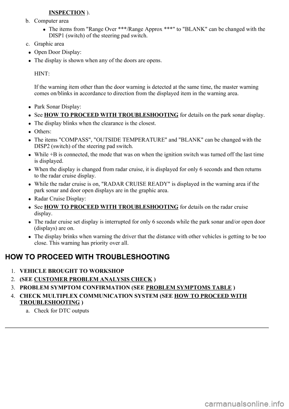
INSPECTION ).
b. Computer area
The items from "Range Over ***/Range Approx ***" to "BLANK" can be changed with the
DISP1 (switch) of the steering pad switch.
c. Graphic area
Open Door Display:
<0037004b004800030047004c00560053004f0044005c0003004c005600030056004b0052005a00510003005a004b00480051000300440051005c00030052004900030057004b00480003004700520052005500560003004400550048000300520053004800
51005600110003[
HINT:
If the warning item other than the door warning is detected at the same time, the master warning
comes on/blinks in accordance to direction from the displayed item in the warning area.
Park Sonar Display:
See HOW TO PROCEED WITH TROUBLESHOOTING for details on the park sonar display.
The display blinks when the clearance is the closest.
Others:
The items "COMPASS", "OUTSIDE TEMPERATURE" and "BLANK" can be changed with the
DISP2 (switch) of the steering pad switch.
While +B is connected, the mode that was on when the ignition switch was turned off the last time
is displayed.
When the display is changed from radar cruise, it is displayed for only 6 seconds and then returns
to the radar cruise display.
While the radar cruise is on, "RADAR CRUISE READY" is displayed in the warning area if the
park sonar and door open displays are in the graphic area.
Radar Cruise Display:
See HOW TO PROCEED WITH TROUBLESHOOTING for details on the radar cruise
display.
The radar cruise set display is interrupted for only 6 seconds while the park sonar and/or open door
(displays) are on.
<0037004b004800030047004c00560053004f0044005c000300450055004c0051004e00560003005a004b004800510003005a004400550051004c0051004a00030057004b0048000300470055004c00590048005500030057004b0044005700030057004b00
4800030047004c0056005700440051004600480003005a004c[th other vehicles is getting to be too
close. This warning has priority over all.
1.VEHICLE BROUGHT TO WORKSHOP
2.(SEE CUSTOMER PROBLEM ANALYSIS CHECK
)
3.PROBLEM SYMPTOM CONFIRMATION (SEE PROBLEM SYMPTOMS TABLE
)
4.CHECK MULTIPLEX COMMUNICATION SYSTEM (SEE HOW TO PROCEED WITH
TROUBLESHOOTING )
a. Check for DTC outputs
Page 1847 of 4500

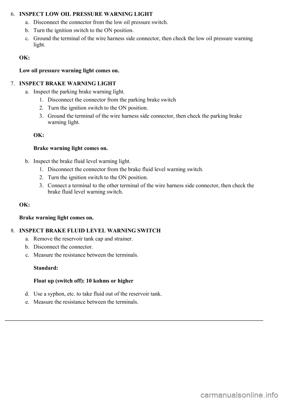
6.INSPECT LOW OIL PRESSURE WARNING LIGHT
a. Disconnect the connector from the low oil pressure switch.
b. Turn the ignition switch to the ON position.
c. Ground the terminal of the wire harness side connector, then check the low oil pressure warning
light.
OK:
Low oil pressure warning light comes on.
7.INSPECT BRAKE WARNING LIGHT
a. Inspect the parking brake warning light.
1. Disconnect the connector from the parking brake switch
2. Turn the ignition switch to the ON position.
3. Ground the terminal of the wire harness side connector, then check the parking brake
warning light.
OK:
Brake warning light comes on.
b. Inspect the brake fluid level warning light.
1. Disconnect the connector from the brake fluid level warning switch.
2. Turn the ignition switch to the ON position.
3. Connect a terminal to the other terminal of the wire harness side connector, then check the
brake fluid level warning switch.
OK:
Brake warning light comes on.
8.INSPECT BRAKE FLUID LEVEL WARNING SWITCH
a. Remove the reservoir tank cap and strainer.
b. Disconnect the connector.
c. Measure the resistance between the terminals.
Standard:
Float up (switch off): 10 kohms or higher
d. Use a syphon, etc. to take fluid out of the reservoir tank.
e. Measure the resistance between the terminals.
Page 1904 of 4500

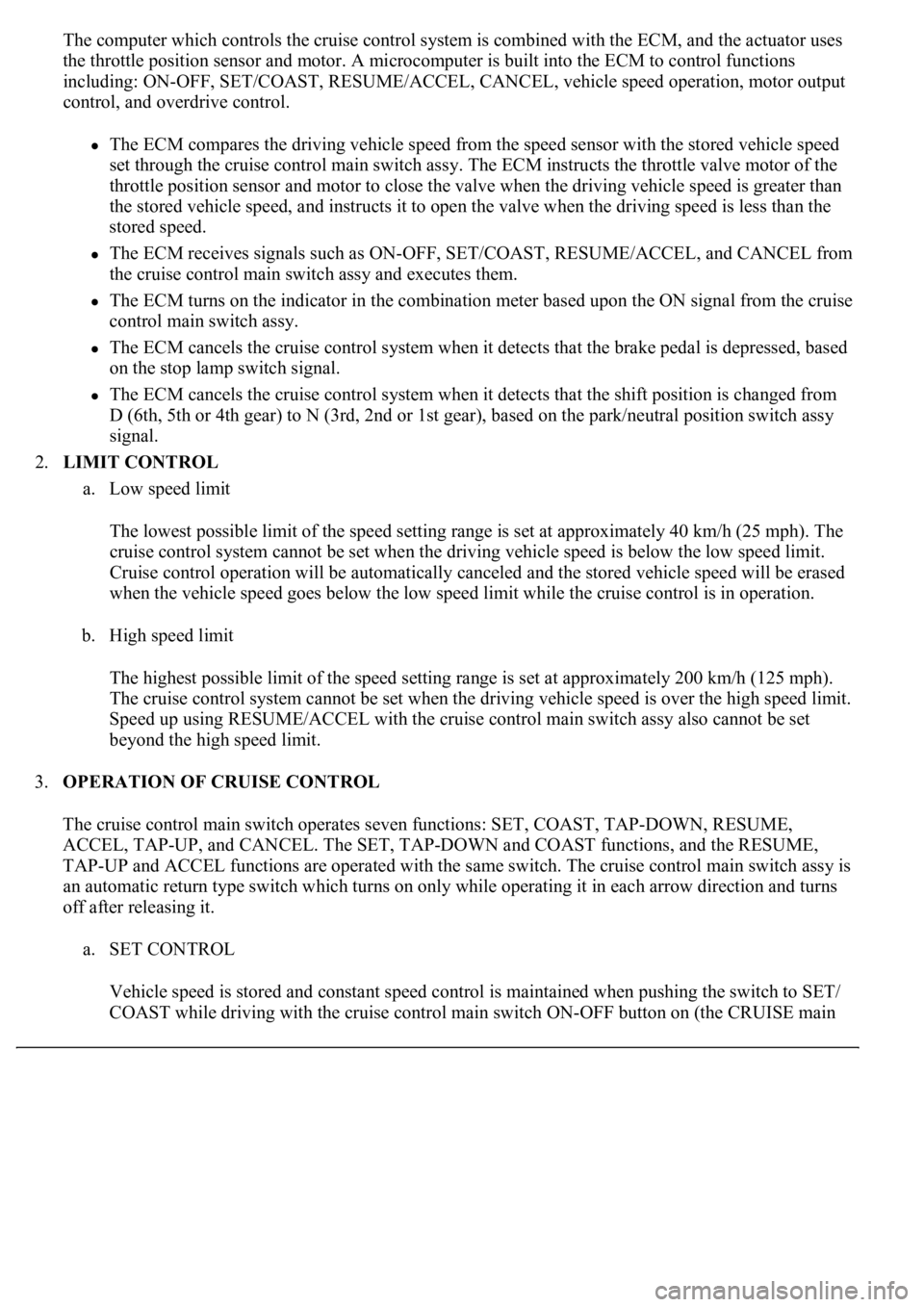
The computer which controls the cruise control system is combined with the ECM, and the actuator uses
the throttle position sensor and motor. A microcomputer is built into the ECM to control functions
including: ON-OFF, SET/COAST, RESUME/ACCEL, CANCEL, vehicle speed operation, motor output
control, and overdrive control.
The ECM compares the driving vehicle speed from the speed sensor with the stored vehicle speed
set through the cruise control main switch assy. The ECM instructs the throttle valve motor of the
throttle position sensor and motor to close the valve when the driving vehicle speed is greater than
the stored vehicle speed, and instructs it to open the valve when the driving speed is less than the
stored speed.
The ECM receives signals such as ON-OFF, SET/COAST, RESUME/ACCEL, and CANCEL from
the cruise control main switch assy and executes them.
The ECM turns on the indicator in the combination meter based upon the ON signal from the cruise
control main switch assy.
The ECM cancels the cruise control system when it detects that the brake pedal is depressed, based
on the stop lamp switch signal.
The ECM cancels the cruise control system when it detects that the shift position is changed from
D (6th, 5th or 4th gear) to N (3rd, 2nd or 1st gear), based on the park/neutral position switch assy
signal.
2.LIMIT CONTROL
a. Low speed limit
The lowest possible limit of the speed setting range is set at approximately 40 km/h (25 mph). The
cruise control system cannot be set when the driving vehicle speed is below the low speed limit.
Cruise control operation will be automatically canceled and the stored vehicle speed will be erased
when the vehicle speed goes below the low speed limit while the cruise control is in operation.
b. High speed limit
The highest possible limit of the speed setting range is set at approximately 200 km/h (125 mph).
The cruise control system cannot be set when the driving vehicle speed is over the high speed limit.
Speed up using RESUME/ACCEL with the cruise control main switch assy also cannot be set
beyond the high speed limit.
3.OPERATION OF CRUISE CONTROL
The cruise control main switch operates seven functions: SET, COAST, TAP-DOWN, RESUME,
ACCEL, TAP-UP, and CANCEL. The SET, TAP-DOWN and COAST functions, and the RESUME,
TAP-UP and ACCEL functions are operated with the same switch. The cruise control main switch assy is
an automatic return type switch which turns on only while operating it in each arrow direction and turns
off after releasing it.
a. SET CONTROL
Vehicle speed is stored and constant speed control is maintained when pushing the switch to SET/
COAST while drivin
g with the cruise control main switch ON-OFF button on (the CRUISE main