Page 2636 of 4500

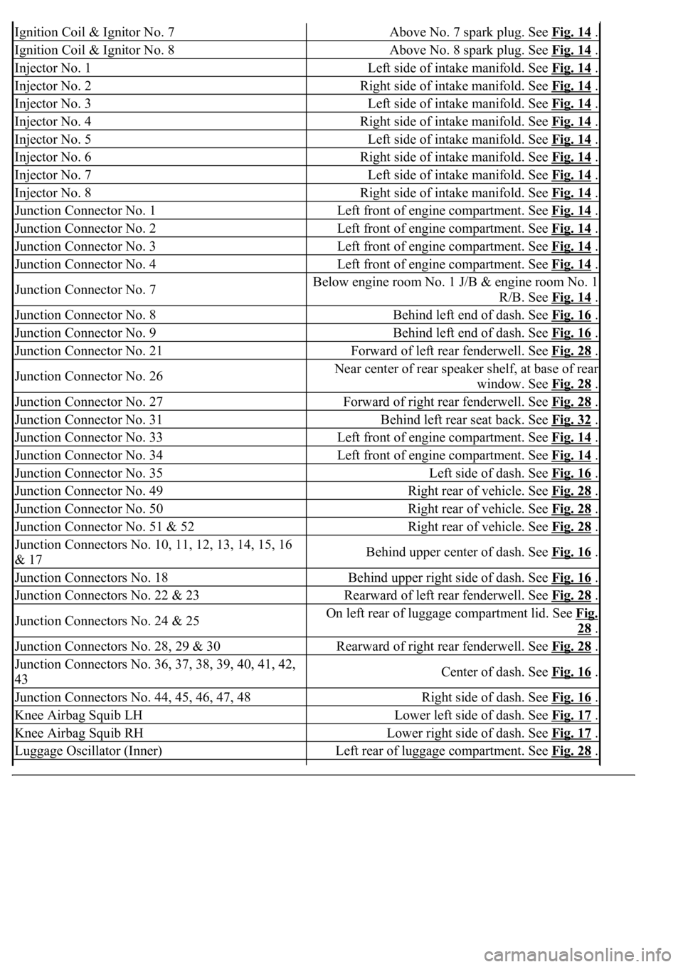
Ignition Coil & Ignitor No. 7Above No. 7 spark plug. See Fig. 14 .
Ignition Coil & Ignitor No. 8Above No. 8 spark plug. See Fig. 14 .
Injector No. 1Left side of intake manifold. See Fig. 14 .
Injector No. 2Right side of intake manifold. See Fig. 14 .
Injector No. 3Left side of intake manifold. See Fig. 14 .
Injector No. 4Right side of intake manifold. See Fig. 14 .
Injector No. 5Left side of intake manifold. See Fig. 14 .
Injector No. 6Right side of intake manifold. See Fig. 14 .
Injector No. 7Left side of intake manifold. See Fig. 14 .
Injector No. 8Right side of intake manifold. See Fig. 14 .
Junction Connector No. 1Left front of engine compartment. See Fig. 14 .
Junction Connector No. 2Left front of engine compartment. See Fig. 14 .
Junction Connector No. 3Left front of engine compartment. See Fig. 14 .
Junction Connector No. 4Left front of engine compartment. See Fig. 14 .
Junction Connector No. 7Below engine room No. 1 J/B & engine room No. 1
R/B. See Fig. 14
.
Junction Connector No. 8Behind left end of dash. See Fig. 16 .
Junction Connector No. 9Behind left end of dash. See Fig. 16 .
Junction Connector No. 21Forward of left rear fenderwell. See Fig. 28 .
Junction Connector No. 26Near center of rear speaker shelf, at base of rear
window. See Fig. 28
.
Junction Connector No. 27Forward of right rear fenderwell. See Fig. 28 .
Junction Connector No. 31Behind left rear seat back. See Fig. 32 .
Junction Connector No. 33Left front of engine compartment. See Fig. 14 .
Junction Connector No. 34Left front of engine compartment. See Fig. 14 .
Junction Connector No. 35Left side of dash. See Fig. 16 .
Junction Connector No. 49Right rear of vehicle. See Fig. 28 .
Junction Connector No. 50Right rear of vehicle. See Fig. 28 .
Junction Connector No. 51 & 52Right rear of vehicle. See Fig. 28 .
<002d0058005100460057004c00520051000300260052005100510048004600570052005500560003003100520011000300140013000f000300140014000f000300140015000f000300140016000f000300140017000f000300140018000f00030014001900
03[
& 17Behind upper center of dash. See Fig. 16 .
Junction Connectors No. 18Behind upper right side of dash. See Fig. 16 .
Junction Connectors No. 22 & 23Rearward of left rear fenderwell. See Fig. 28 .
Junction Connectors No. 24 & 25On left rear of luggage compartment lid. See Fig.
28 .
Junction Connectors No. 28, 29 & 30Rearward of right rear fenderwell. See Fig. 28 .
<002d0058005100460057004c00520051000300260052005100510048004600570052005500560003003100520011000300160019000f00030016001a000f00030016001b000f00030016001c000f000300170013000f000300170014000f00030017001500
0f0003[
43Center of dash. See Fig. 16 .
Junction Connectors No. 44, 45, 46, 47, 48Right side of dash. See Fig. 16 .
Knee Airbag Squib LHLower left side of dash. See Fig. 17 .
Knee Airbag Squib RHLower right side of dash. See Fig. 17 .
Luggage Oscillator (Inner)Left rear of luggage compartment. See Fig. 28 .
Page 2671 of 4500
LOCATION
Fig. 1: Identifying Electronic Controlled Automatic Transmission Components Location (1 Of 2)
Courtesy of TOYOTA MOTOR SALES, U.S.A., INC.
PNP switch, NSWPark/neutral position switch
Pressure control solenoidTransmission pressure control solenoid
Shift solenoidTransmission shift solenoid valve
Transmission control switch, Shift lock control unitShift lock control module
Engine immobilizer system, Immobilizer systemVehicle anti-theft system
Page 2676 of 4500

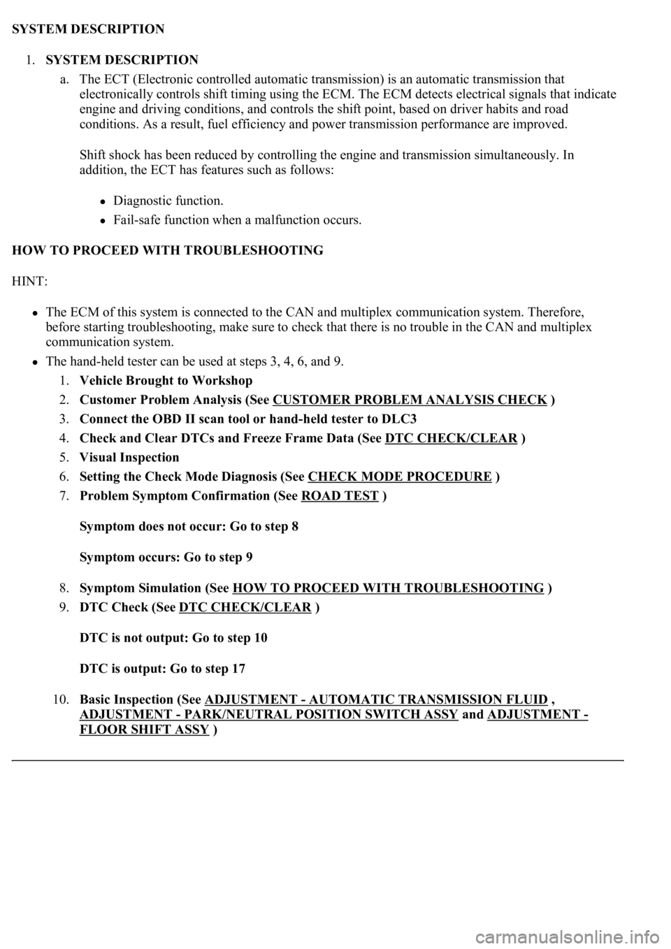
SYSTEM DESCRIPTION
1.SYSTEM DESCRIPTION
a. The ECT (Electronic controlled automatic transmission) is an automatic transmission that
electronically controls shift timing using the ECM. The ECM detects electrical signals that indicate
engine and driving conditions, and controls the shift point, based on driver habits and road
conditions. As a result, fuel efficiency and power transmission performance are improved.
<0036004b004c0049005700030056004b00520046004e0003004b00440056000300450048004800510003005500480047005800460048004700030045005c0003004600520051005700550052004f004f004c0051004a00030057004b004800030048005100
4a004c00510048000300440051004700030057005500440051[smission simultaneously. In
addition, the ECT has features such as follows:
Diagnostic function.
Fail-safe function when a malfunction occurs.
HOW TO PROCEED WITH TROUBLESHOOTING
HINT:
The ECM of this system is connected to the CAN and multiplex communication system. Therefore,
before starting troubleshooting, make sure to check that there is no trouble in the CAN and multiplex
communication system.
<0037004b00480003004b0044005100470010004b0048004f0047000300570048005600570048005500030046004400510003004500480003005800560048004700030044005700030056005700480053005600030016000f00030017000f00030019000f00
030044005100470003001c00110003[
1.Vehicle Brought to Workshop
2.Customer Problem Analysis (See CUSTOMER PROBLEM ANALYSIS CHECK
)
3.Connect the OBD II scan tool or hand-held tester to DLC3
4.Check and Clear DTCs and Freeze Frame Data (See DTC CHECK/CLEAR
)
5.Visual Inspection
6.Setting the Check Mode Diagnosis (See CHECK MODE PROCEDURE
)
7.Problem Symptom Confirmation (See ROAD TEST
)
Symptom does not occur: Go to step 8
Symptom occurs: Go to step 9
8.Symptom Simulation (See HOW TO PROCEED WITH TROUBLESHOOTING
)
9.DTC Check (See DTC CHECK/CLEAR
)
DTC is not output: Go to step 10
DTC is output: Go to step 17
10.Basic Inspection (See ADJUSTMENT
- AUTOMATIC TRANSMISSION FLUID ,
ADJUSTMENT
- PARK/NEUTRAL POSITION SWITCH ASSY and ADJUSTMENT -
FLOOR SHIFT ASSY
)
Page 2681 of 4500
d. P position test:
Stop the vehicle on a grade (more than 5°) and after shifting into the P position, release the parking
brake. Then, check that the parking lock pawl holds the vehicle in place.
MECHANICAL SYSTEM TESTS
1.PERFORM MECHANICAL SYSTEM TESTS
a. Measure the stall speed.
The object of this test is to check the overall performance of the transmission and engine by
measuring the stall speeds in the D and R positions.
1. Chock the 4 wheels.
2. Connect an OBD II scan tool or hand-held tester to the DLC3.
3. Fully apply the parking brake.
4. Keep your left foot pressed firmly on the brake pedal.
5. Start the engine.
6. Shift into the D position. Press all the way down on the accelerator pedal with your right
foot.
7. Quickly read the stall speed at this time.
Stall speed: 2,400 +/- 150 rpm
8. Do the same test in the R position.
Stall speed: 2,400 +/- 150 rpm
Evaluation:
Page 2682 of 4500
Fig. 7: Mechanical Systems Problem Symptoms Chart
Courtesy of TOYOTA MOTOR SALES, U.S.A., INC.
b. Measure the time lag.
1. When the shift lever is shifted while the engine is idling, there will be a certain time lapse or
lag before the shock can be felt. This is used for checking the condition of the direct clutch,
forward clutch, and 1st and reverse brake.
2. Connect an OBD II scan tool or hand-held tester to the DLC3.
3. Fully apply the parking brake.
4. Start and warm up the engine and check idle speed.
Idle speed: approx. 700 rpm (In N position and A/C OFF)
5. Shift the lever from N to D position. Using a stop watch, measure the time from when the
lever is shifted until the shock is felt.
Time lag: N --> D less than 1.2 seconds
6. In the same way, measure the time lag for N --> R.
Time lag: N --> R less than 1.5 seconds
Evaluation (If N --> D or N --> R time lag is longer than the specified):
Page 2683 of 4500
Fig. 8: Time Lag Problem Symptoms Chart
Courtesy of TOYOTA MOTOR SALES, U.S.A., INC.
HYDRAULIC TEST
1.PERFORM HYDRAULIC TEST
a. Measure the line pressure.
1. Warm up the ATF (Automatic Transmission Fluid).
2. Lift the vehicle up.
3. Remove the test plug on the transmission case center right side and connect SST.
SST 09992-00095 (09992-00231, 09992-00271)
4. Fully apply the parking brake and chock the 4 wheels.
5. Start the engine and check idling speed.
6. Keep your left foot pressing firmly on the brake pedal and shift into D position.
7. Measure the line pressure when the engine is idling.
8. Depress the accelerator pedal all the way down. Quickly read the highest line pressure when
en
gine speed reaches stall speed.
Page 2725 of 4500
Fig. 46: Test Item Reference Chart
Courtesy of TOYOTA MOTOR SALES, U.S.A., INC.
HINT:
The pressure values in ACTIVE TEST and HYDRAULIC TEST are different from each other.
DIAGNOSTIC TROUBLE CODE CHART
If a DTC is displayed during the DTC check, check the parts listed in the table below.
DTC LIST
DTCDescription
DTC P0705, P0850TRANSMISSION RANGE SENSOR CIRCUIT
MALFUNCTION (PRNDL INPUT),
PARK/NEUTRAL SWITCH INPUT CIRCUIT
DTC P0710, P0712, P0713TRANSMISSION FLUID TEMPERATURE
SENSOR "A" CIRCUIT LOW/HIGH INPUT
DTC P0711TRANSMISSION FLUID TEMPERATURE
SENSOR "A" PERFORMANCE
DTC P0717TURBINE SPEED SENSOR CIRCUIT NO SIGNAL
DTC P0724BRAKE SWITCH "B" CIRCUIT HIGH
DTC P0729GEAR 6 INCORRECT RATIO
DTC P0748PRESSURE CONTROL SOLENOID "A"
ELECTRICAL (SHIFT SOLENOID VALVE SL1)
Page 2728 of 4500
Fig. 48: Diagnostic Trouble Code Reference Chart (2 Of 2)
Courtesy of TOYOTA MOTOR SALES, U.S.A., INC.
DTC P0705, P0850: TRANSMISSION RANGE SENSOR CIRCUIT MALFUNCTION (PRNDL INPUT),
PARK/NEUTRAL SWITCH INPUT CIRCUIT