Page 451 of 4500
a. Measure the resistance according to the value (s) in the table below.
Standard:
LUGGAGE ROOM J/B - REAR MAGNETIC VALVE VOLTAGE
NG: REPAIR OR REPLACE HARNESS OR CONNECTOR
Fig. 187: Identifying Terminals Of R38 Rear Magnetic Valve Connector
Courtesy of TOYOTA MOTOR SALES, U.S.A., INC.
OK: Go to next step
4.INSPECT REAR MAGNETIC VALVE
Tester connectionConditionSpecified condition
R38-1 - Body groundIgnition switch OFF --> ONBelow 1 V --> 10 V to 14 V
Page 452 of 4500
a. Remove the rear magnetic valve.
b. Check the air passage through the valve with and without the battery positive voltage applied
between terminals as shown in the chart.
Standard:
REAR MAGNETIC VALVE SPECIFIED CONDITION
NG: REPLACE REAR MAGNETIC VALVE
Fig. 188: Identifying Terminals Of Rear Magnetic Valve
Courtesy of TOYOTA MOTOR SALES, U.S.A., INC.
OK: REPAIR OR REPLACE HARNESS OR CONNECTOR (REAR MAGNETIC VALVE -
LUGGAGE ROOM J/B ECU)
ConditionSpecified condition
Apply B+ between terminalsFree passage
No Apply B+ between terminalsNo passage
Page 459 of 4500
Fig. 192: Identifying Terminals Of S47 Smoke Sensor Connector
Courtesy of TOYOTA MOTOR SALES, U.S.A., INC.
OK: Go to next step
4.CHECK HARNESS AND CONNECTOR (LUGGAGE ROOM J/B - SMOKE SENSOR) (SEE
ELECTRONIC CIRCUIT INSPECTION PROCEDURE
)
a. Measure the resistance according to the value (s) in the table below.
Standard:
LUGGAGE ROOM J/B - SMOKE SENSOR RESISTANCE
Tester connectionConditionSpecified condition
L14-16 (SMOK) - S47-2AlwaysBelow 1 ohms
L14-16 (SMOK) - Body groundAlways10 kohms or higher
Page 468 of 4500
SYSTEM REFERENCE
Fig. 1: Identifying DLC3 Connector Terminals
Courtesy of TOYOTA MOTOR SALES, U.S.A., INC.
System NameSee Procedure
Front Power Seat Control SystemINITIALIZATION
Page 470 of 4500
Fig. 2: Identifying Air Suspension System Components Location
Courtesy of TOYOTA MOTOR SALES, U.S.A., INC.
Page 480 of 4500

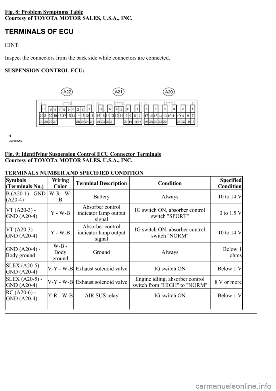
Fig. 8: Problem Symptoms Table
Courtesy of TOYOTA MOTOR SALES, U.S.A., INC.
HINT:
Inspect the connectors from the back side while connectors are connected.
SUSPENSION CONTROL ECU:
Fig. 9: Identifying Suspension Control ECU Connector Terminals
Courtesy of TOYOTA MOTOR SALES, U.S.A., INC.
TERMINALS NUMBER AND SPECIFIED CONDITION
Symbols
(Terminals No.)Wiring
ColorTerminal DescriptionConditionSpecified
Condition
B (A20-1) - GND
(A20-4)W-R - W-
BBatteryAlways10 to 14 V
VT (A20-3) -
GND (A20-4)Y - W-B
Absorber control
indicator lamp output
signalIG switch ON, absorber control
switch "SPORT"0 to 1.5 V
VT (A20-3) -
GND (A20-4)Y - W-B
Absorber control
indicator lamp output
signalIG switch ON, absorber control
switch "NORM"10 to 14 V
GND (A20-4) -
Body groundW-B -
Body
ground
GroundAlwaysBelow 1
ohms
SLEX (A20-5) -
GND (A20-4)V-Y - W-BExhaust solenoid valveIG switch ONBelow 1 V
SLEX (A20-5) -
GND (A20-4)V-Y - W-BExhaust solenoid valveEngine idling, absorber control
switch from "HIGH" to "NORM"8 V or more
RC (A20-6) -
GND (A20-4)Y-R - W-BAIR SUS relayIG switch ONBelow 1 V
Page 484 of 4500
Fig. 10: Identifying DLC3 Connector Terminals
Courtesy of TOYOTA MOTOR SALES, U.S.A., INC.
TERMINALS NUMBER AND SPECIFIED CONDITION
Symbols (Terminals No.)Terminal DescriptionConditionSpecified
Condition
SIL (7) - SG (5)Bus "+" lineDuring
communicationPulse generation
CG (4) - Body groundChassis groundAlwaysBelow 1 ohms
SG (5) - Body groundSignal groundAlwaysBelow 1 ohms
BAT (16) - Body groundBattery positiveAlways11 to 14 V
CANH (6) - CANL (14)HIGH-level CAN bus
lineIG switch OFF54 to 67 ohms
CANH (6) - Battery positiveHIGH-level CAN bus
lineIG switch OFF1 Mohms or higher
CANH (6) - CG (4)HIGH-level CAN bus
lineIG switch OFF3 Kohms or higher
CANL (14) - Battery
positiveLOW-level CAN bus
lineIG switch OFF1 Mohms or higher
Page 486 of 4500
Fig. 11: Identifying Absorber Control Indicator Lamp Location (1 Of 2)
Courtesy of TOYOTA MOTOR SALES, U.S.A., INC.
d. DTCs (Normal mode)
1. DTCs are memorized in the suspension control ECU and read by using the hand-held tester
(SEE DTC CHECK/CLEAR
for the procedure of DTCs check).
e. Test mode
1. By switching from normal mode into test mode, you can inspect the height control switch,
absorber control switch, front acceleration sensor and rear acceleration sensor (SEE TEST
MODE PROCEDURE ).
2.CHECK INDICATOR LAMP
1. Turn the ignition switch to the ON position.
2. Check that the absorber control indicator lamp comes on for 2 seconds.
If the indicator check result is not normal, proceed to troubleshooting for the indicator lamp circuit.
TROUBLE AREA REFERENCE
Trouble AreaSee Procedure
Absorber control indicator lamp ABSORBER CONTROL INDICATOR LAMP