Page 230 of 4500

Fig. 22: Identifying Air Conditioning Amplifier Connector Front View
Courtesy of TOYOTA MOTOR SALES, U.S.A., INC.
AIR CONDITIONING AMPLIFIER CONNECTOR SPECIFICATIONS
ItemTest Details / Display (Range)Diagnostic Note
ACTUATOR CHECKActuator check / OFF, ON-
Symbols
(Terminal No.)Wiring
colorTerminal DescriptionConditionSpecification
GND - Body
ground (A11-1 -
Body ground)W-B -
Body
groundGround for main power
supplyAlwaysBelow 1.0
ohms
MPX+ (A11-2)GR-BMultiplex communication
systemMultiplex communication circuit-
ACC - GND
(A11-3 - A11-1)GR - W-
BPower source (ACC)Turn ignition switch to ACC.10 to 14 V
MPX- (A11-4)GR-BMultiplex communication
systemMultiplex communication circuit-
BLW - GND
(A11-5 - A11-1)LG-B -
W-BBlower motor speed
control voltageBlower fan speed OFF --> M2 -->
HIPulse
generation
SOL+ - SOL-
(A11-6 - A11-7)P - Y-BCompressor operation
signalA/C magnetic clutch to ON.Pulse
generation
RDFGR - GND
(A11-8 - A11-1)W - W-BRear defogger operation
voltageIgnition switch ON. Rear
defogger switch to OFF.10 to 14 V
RDFGR - GND
(A11-8 - A11-1)W - W-BRear defogger operation
voltageIgnition switch ON. Rear
defogger switch to ON.Below 1.0 V
IG - GND (A11-9
- A11-1)LG-R -
W-BPower source (IG)Ignition switch ON.10 to 14 V
Page 237 of 4500

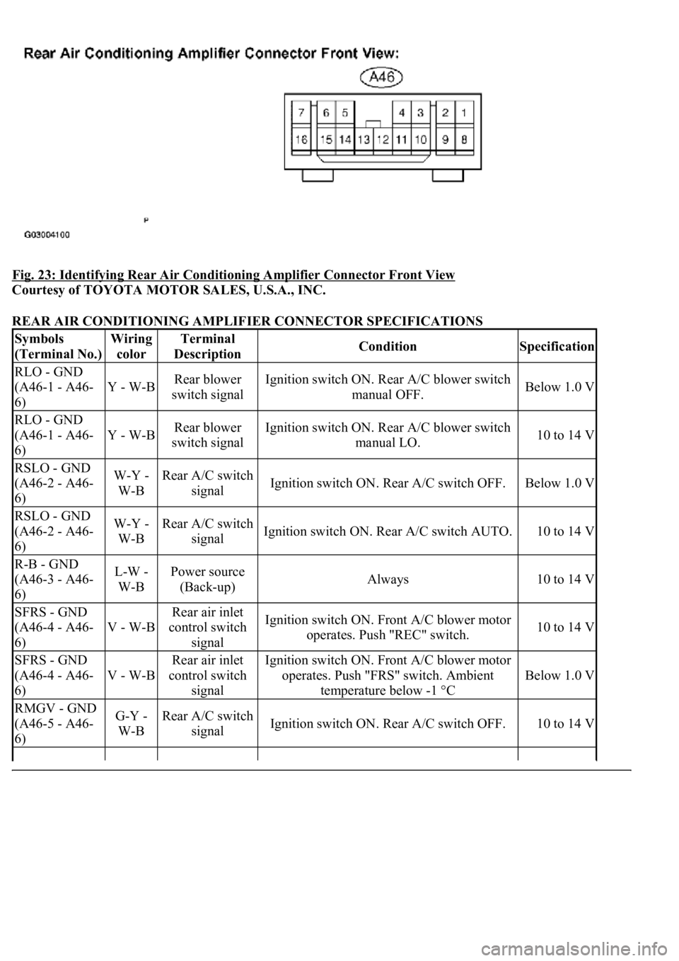
Fig. 23: Identifying Rear Air Conditioning Amplifier Connector Front View
Courtesy of TOYOTA MOTOR SALES, U.S.A., INC.
REAR AIR CONDITIONING AMPLIFIER CONNECTOR SPECIFICATIONS
Symbols
(Terminal No.)Wiring
colorTerminal
DescriptionConditionSpecification
RLO - GND
(A46-1 - A46-
6)
Y - W-BRear blower
switch signalIgnition switch ON. Rear A/C blower switch
manual OFF.Below 1.0 V
RLO - GND
(A46-1 - A46-
6)
Y - W-BRear blower
switch signalIgnition switch ON. Rear A/C blower switch
manual LO.10 to 14 V
RSLO - GND
(A46-2 - A46-
6)W-Y -
W-BRear A/C switch
signalIgnition switch ON. Rear A/C switch OFF.Below 1.0 V
RSLO - GND
(A46-2 - A46-
6)W-Y -
W-BRear A/C switch
signalIgnition switch ON. Rear A/C switch AUTO.10 to 14 V
R-B - GND
(A46-3 - A46-
6)L-W -
W-BPower source
(Back-up)Always10 to 14 V
SFRS - GND
(A46-4 - A46-
6)
V - W-B
Rear air inlet
control switch
signalIgnition switch ON. Front A/C blower motor
operates. Push "REC" switch.10 to 14 V
SFRS - GND
(A46-4 - A46-
6)
V - W-B
Rear air inlet
control switch
signalIgnition switch ON. Front A/C blower motor
operates. Push "FRS" switch. Ambient
temperature below -1 °C
Below 1.0 V
RMGV - GND
(A46-5 - A46-
6)G-Y -
W-BRear A/C switch
signalIgnition switch ON. Rear A/C switch OFF.10 to 14 V
Page 239 of 4500

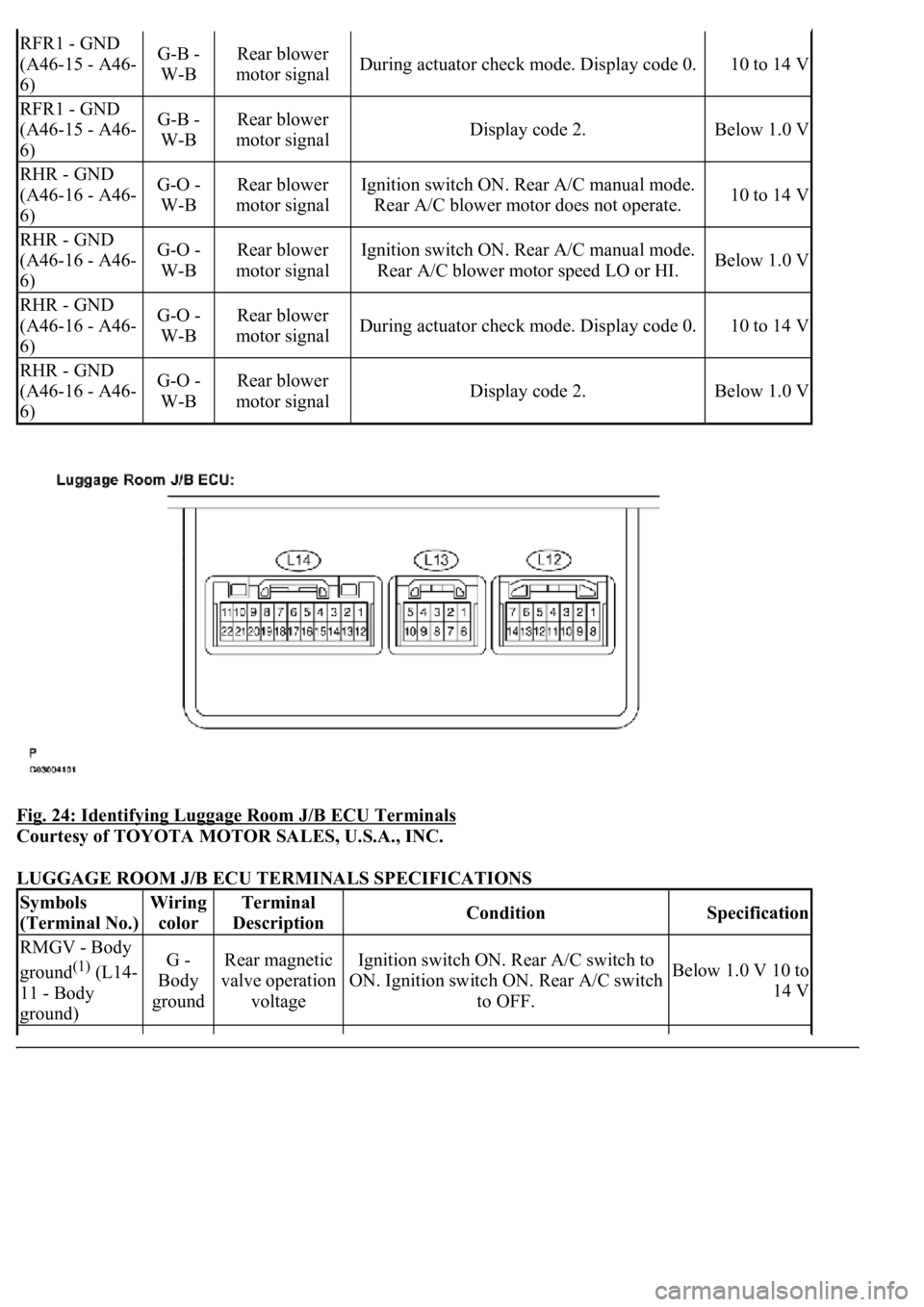
Fig. 24: Identifying Luggage Room J/B ECU Terminals
Courtesy of TOYOTA MOTOR SALES, U.S.A., INC.
LUGGAGE ROOM J/B ECU TERMINALS SPECIFICATIONS
RFR1 - GND
(A46-15 - A46-
6)G-B -
W-BRear blower
motor signalDuring actuator check mode. Display code 0.10 to 14 V
RFR1 - GND
(A46-15 - A46-
6)G-B -
W-BRear blower
motor signalDisplay code 2.Below 1.0 V
RHR - GND
(A46-16 - A46-
6)G-O -
W-BRear blower
motor signalIgnition switch ON. Rear A/C manual mode.
Rear A/C blower motor does not operate.10 to 14 V
RHR - GND
(A46-16 - A46-
6)G-O -
W-BRear blower
motor signalIgnition switch ON. Rear A/C manual mode.
Rear A/C blower motor speed LO or HI.Below 1.0 V
RHR - GND
(A46-16 - A46-
6)G-O -
W-BRear blower
motor signalDuring actuator check mode. Display code 0.10 to 14 V
RHR - GND
(A46-16 - A46-
6)G-O -
W-BRear blower
motor signalDisplay code 2.Below 1.0 V
Symbols
(Terminal No.)Wiring
colorTerminal
DescriptionConditionSpecification
RMGV - Body
ground
(1) (L14-
11 - Body
ground)G -
Body
groundRear magnetic
valve operation
voltageIgnition switch ON. Rear A/C switch to
ON. Ignition switch ON. Rear A/C switch
to OFF.Below 1.0 V 10 to
14 V
Page 242 of 4500
Fig. 25: Identifying Front DEF Indicator (W/O Lexus Navigation System)
Courtesy of TOYOTA MOTOR SALES, U.S.A., INC.
Page 243 of 4500
Fig. 26: Identifying Front DEF Indicator (W/ Lexus Navigation System)
Courtesy of TOYOTA MOTOR SALES, U.S.A., INC.
2. If mode indication is different from the actual air outlet in actuator check, turn the ignition switch
to the ON or START position while pressing the "Rr DEF" and "OFF" switches simultaneously.
STEP motor initialization occurs and the "DEF" indicator blinks.
Page 244 of 4500
Fig. 27: Identifying Rear DEF, OFF Switch (W/O Lexus Navigation System)
Courtesy of TOYOTA MOTOR SALES, U.S.A., INC.
Page 245 of 4500
Fig. 28: Identifying Rear DEF, OFF Switch (W/ Lexus Navigation System)
Courtesy of TOYOTA MOTOR SALES, U.S.A., INC.
Front A/C
Page 253 of 4500
Fig. 37: Identifying Terminals Of A14 A/C Room Temperature Sensor Connector
Courtesy of TOYOTA MOTOR SALES, U.S.A., INC.
HINT:
As the temperature increases, the resistance decreases (see the
graph below).