Page 214 of 4500

The hand-held tester can be used in steps 3, 6, 7 and 11.
1.VEHICLE BROUGHT TO WORK SHOP
2.(SEE CUSTOMER PROBLEM ANALYSIS CHECK
)
a. Confirm problem symptoms.
3.CHECK AND CLEAR THE DTCS (SEE DTC CHECK/CLEAR
)
4.PROBLEM SYMPTOM CONFIRMATION
SYMPTOM OCCURS (GO TO STEP 6)
SYMPTOM DOES NOT OCCUR (GO TO STEP 5)
5.SYMPTOM SIMULATION (SEE HOW TO PROCEED WITH TROUBLESHOOTING
)
6.CHECK BODY MULTIPLEX COMMUNICATION SYSTEM (SEE HOW TO PROCEED WITH
TROUBLESHOOTING )
a. Check for the DTC output.
MULTIPLEX DTC OUTPUTS (PROCEED TO "MULTIPLEX COMMUNICATION SYSTEM
")
NO MULTIPLEX DTC (GO TO STEP 7)
7.CHECK CAN COMMUNICATION SYSTEM (SEE HOW TO PROCEED WITH
TROUBLESHOOTING )
a. Check for the DTC output.
CAN DTC OUTPUTS (PROCEED TO "CAN COMMUNICATION SYSTEM
")
NO CAN DTC (GO TO STEP 8)
8.DTC CHECK (OTHER THAN MULTIPLEX DTC) (SEE DTC CHECK/CLEAR
)
MALFUNCTION CODE (GO TO STEP 9)
NORMAL CODE (GO TO STEP 10)
9.(SEE DIAGNOSTIC TROUBLE CODE CHART
)
GO TO STEP 12
10.(SEE PROBLEM SYMPTOMS TABLE
)
11.(SEE ACTUATOR CHECK
)
12.CIRCUIT INSPECTION (SEE DTC B1411 ROOM TEMPERATURE SENSOR CIRCUIT
to
INTELLIGENT SWING REGISTER CIRCUIT
)
13.IDENTIFYING OF PROBLEMS
Page 217 of 4500

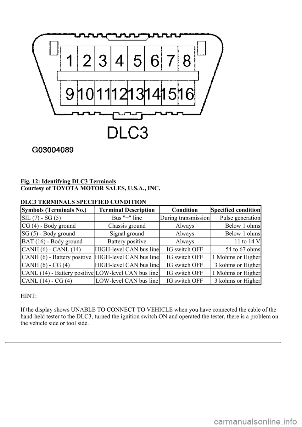
Fig. 12: Identifying DLC3 Terminals
Courtesy of TOYOTA MOTOR SALES, U.S.A., INC.
DLC3 TERMINALS SPECIFIED CONDITION
HINT:
If the display shows UNABLE TO CONNECT TO VEHICLE when you have connected the cable of the
hand-held tester to the DLC3, turned the ignition switch ON and operated the tester, there is a problem on
the vehicle side or tool side.
Symbols (Terminals No.)Terminal DescriptionConditionSpecified condition
SIL (7) - SG (5)Bus "+" lineDuring transmissionPulse generation
CG (4) - Body groundChassis groundAlwaysBelow 1 ohms
SG (5) - Body groundSignal groundAlwaysBelow 1 ohms
BAT (16) - Body groundBattery positiveAlways11 to 14 V
CANH (6) - CANL (14)HIGH-level CAN bus lineIG switch OFF54 to 67 ohms
CANH (6) - Battery positiveHIGH-level CAN bus lineIG switch OFF1 Mohms or Higher
CANH (6) - CG (4)HIGH-level CAN bus lineIG switch OFF3 kohms or Higher
CANL (14) - Battery positiveLOW-level CAN bus lineIG switch OFF1 Mohms or Higher
CANL (14) - CG (4)LOW-level CAN bus lineIG switch OFF3 kohms or Higher
Page 218 of 4500
If the communication is normal when the tool is connected to another vehicle, inspect the DLC3 on
the original vehicle.
If the communication is still impossible when the tool is connected to another vehicle, the problem
is probably in the tool itself, so consult the Service Department listed in the tool's instruction
manual.
1.INDICATOR CHECK
a. Turn the ignition switch to the ON position while pressing the A/C control AUTO switch and R/F
(Recirculation/Fresh) switch simultaneously.
Fig. 13: Identifying Auto Switch (W/O LEXUS Navigation System)
Courtesy of TOYOTA MOTOR SALES, U.S.A., INC.
b. Check that the all indicators come on and go off 4 times in succession at 1 second intervals.
HINT:
After the indicator check is completed, the system enters the DTC mode automatically.
Press the "OFF" switch to cancel the indicator mode.
Page 219 of 4500
Fig. 14: Identifying Auto Switch (W/ LEXUS Navigation System)
Courtesy of TOYOTA MOTOR SALES, U.S.A., INC.
Page 222 of 4500
Fig. 17: Identifying R/F Switch And Code Display (W/O Lexus Navigation System)
Courtesy of TOYOTA MOTOR SALES, U.S.A., INC.
If a slower display is desired, press the driver temperature up switch and change the display in the STEP
operation. Each time the driver temperature up switch is pressed, the display changes by 1 STEP.
Page 223 of 4500
Fig. 18: Identifying R/F Switch And Code Display (W/ Lexus Navigation System)
Courtesy of TOYOTA MOTOR SALES, U.S.A., INC.
HINT:
<0037004b0048000300450058005d005d0048005500030056005200580051004700560003005a004b0048005100030057004b004800030047004c00560053004f0044005c00480047000300570055005200580045004f004800030046005200470048000300
46004b00440051004a00480056001100030003[
Codes are displayed from the smaller to the larger numbers in order.
To cancel the check mode, press the "OFF" switch.
Page 224 of 4500
Fig. 19: Identifying UP Switch (W/O Lexus Navigation System)
Courtesy of TOYOTA MOTOR SALES, U.S.A., INC.
Page 225 of 4500
Fig. 20: Identifying UP Switch (W/ Lexus Navigation System)
Courtesy of TOYOTA MOTOR SALES, U.S.A., INC.