2003 DODGE RAM Front hub assembly
[x] Cancel search: Front hub assemblyPage 2187 of 2895
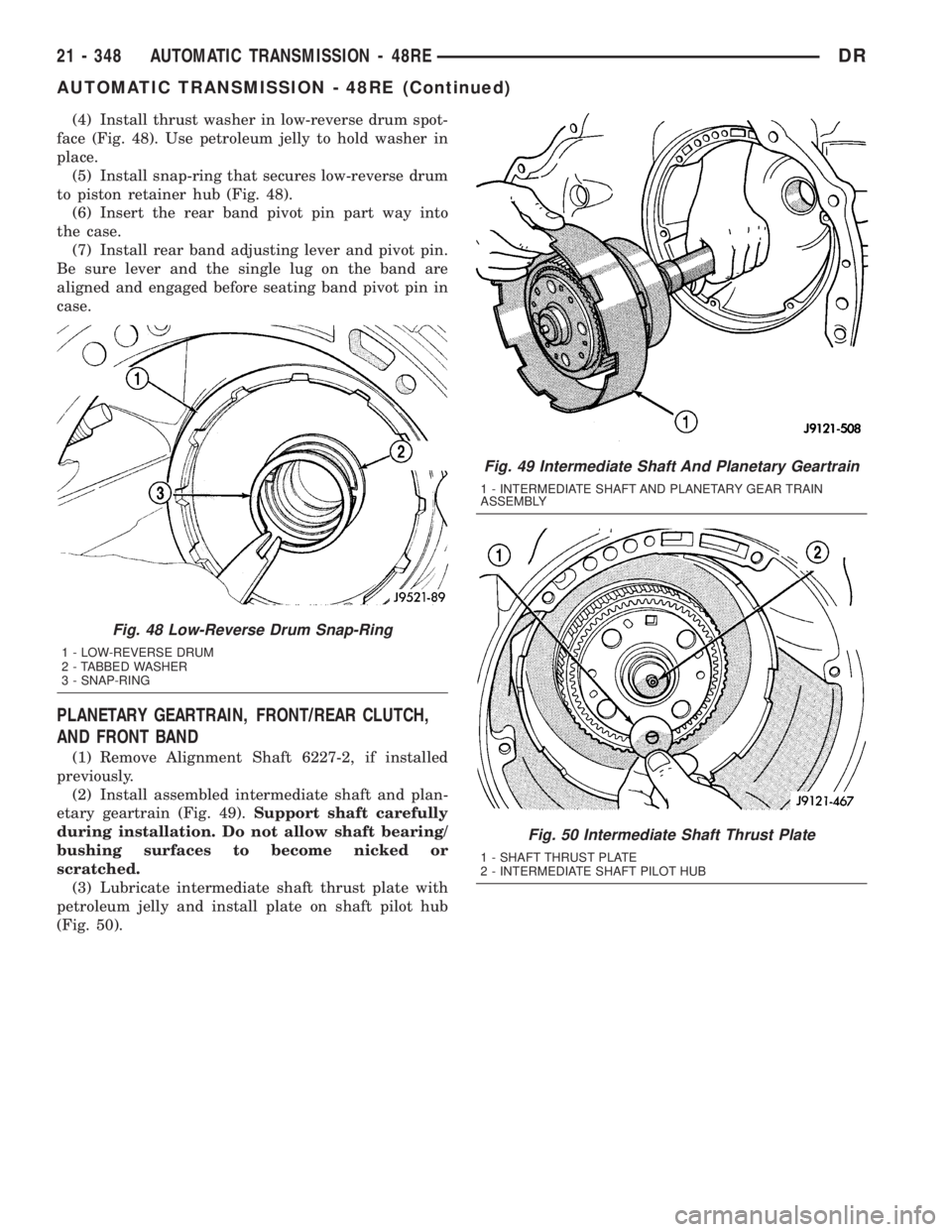
(4) Install thrust washer in low-reverse drum spot-
face (Fig. 48). Use petroleum jelly to hold washer in
place.
(5) Install snap-ring that secures low-reverse drum
to piston retainer hub (Fig. 48).
(6) Insert the rear band pivot pin part way into
the case.
(7) Install rear band adjusting lever and pivot pin.
Be sure lever and the single lug on the band are
aligned and engaged before seating band pivot pin in
case.
PLANETARY GEARTRAIN, FRONT/REAR CLUTCH,
AND FRONT BAND
(1) Remove Alignment Shaft 6227-2, if installed
previously.
(2) Install assembled intermediate shaft and plan-
etary geartrain (Fig. 49).Support shaft carefully
during installation. Do not allow shaft bearing/
bushing surfaces to become nicked or
scratched.
(3) Lubricate intermediate shaft thrust plate with
petroleum jelly and install plate on shaft pilot hub
(Fig. 50).
Fig. 49 Intermediate Shaft And Planetary Geartrain
1 - INTERMEDIATE SHAFT AND PLANETARY GEAR TRAIN
ASSEMBLY
Fig. 50 Intermediate Shaft Thrust Plate
1 - SHAFT THRUST PLATE
2 - INTERMEDIATE SHAFT PILOT HUB
Fig. 48 Low-Reverse Drum Snap-Ring
1 - LOW-REVERSE DRUM
2 - TABBED WASHER
3 - SNAP-RING
21 - 348 AUTOMATIC TRANSMISSION - 48REDR
AUTOMATIC TRANSMISSION - 48RE (Continued)
Page 2188 of 2895
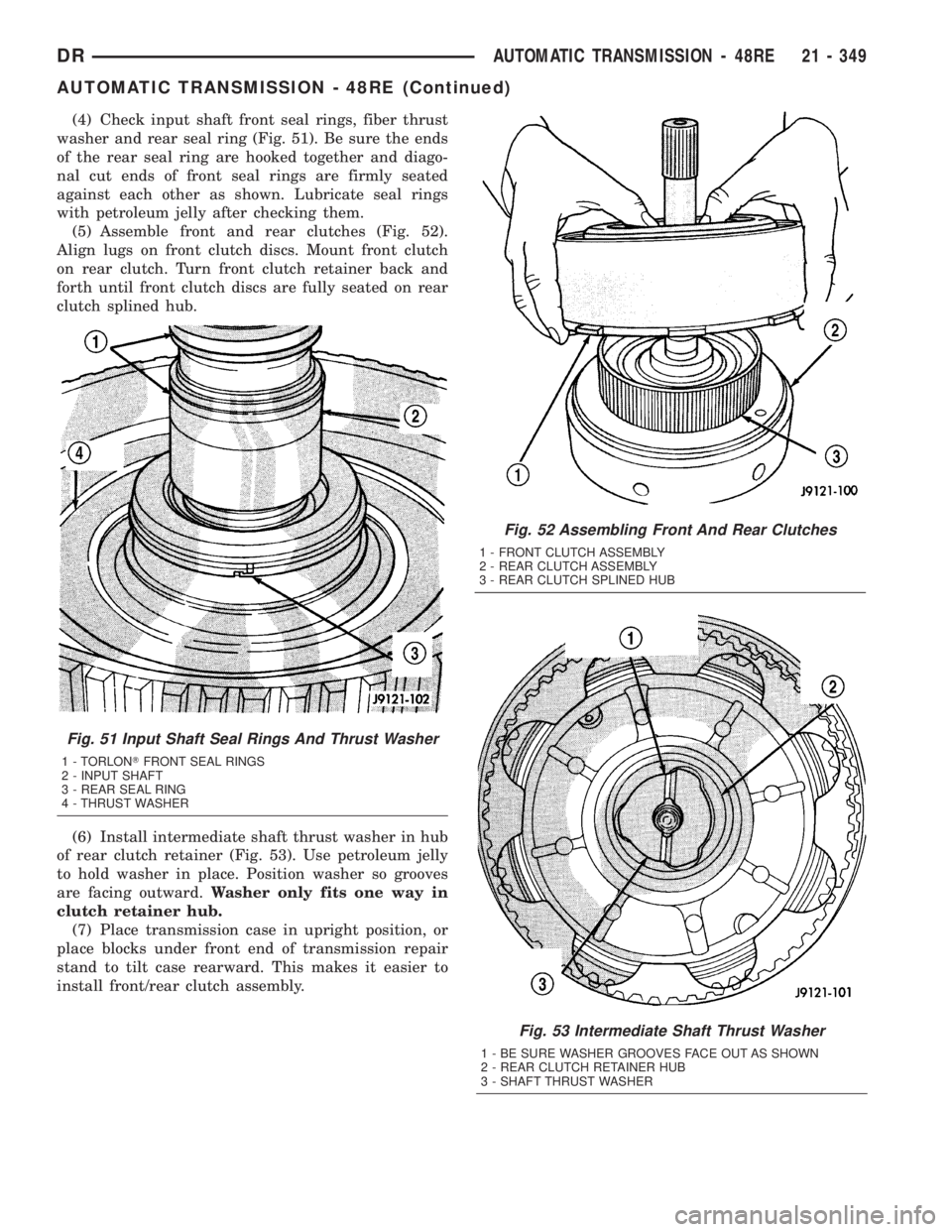
(4) Check input shaft front seal rings, fiber thrust
washer and rear seal ring (Fig. 51). Be sure the ends
of the rear seal ring are hooked together and diago-
nal cut ends of front seal rings are firmly seated
against each other as shown. Lubricate seal rings
with petroleum jelly after checking them.
(5) Assemble front and rear clutches (Fig. 52).
Align lugs on front clutch discs. Mount front clutch
on rear clutch. Turn front clutch retainer back and
forth until front clutch discs are fully seated on rear
clutch splined hub.
(6) Install intermediate shaft thrust washer in hub
of rear clutch retainer (Fig. 53). Use petroleum jelly
to hold washer in place. Position washer so grooves
are facing outward.Washer only fits one way in
clutch retainer hub.
(7) Place transmission case in upright position, or
place blocks under front end of transmission repair
stand to tilt case rearward. This makes it easier to
install front/rear clutch assembly.
Fig. 52 Assembling Front And Rear Clutches
1 - FRONT CLUTCH ASSEMBLY
2 - REAR CLUTCH ASSEMBLY
3 - REAR CLUTCH SPLINED HUB
Fig. 53 Intermediate Shaft Thrust Washer
1 - BE SURE WASHER GROOVES FACE OUT AS SHOWN
2 - REAR CLUTCH RETAINER HUB
3 - SHAFT THRUST WASHER
Fig. 51 Input Shaft Seal Rings And Thrust Washer
1 - TORLONTFRONT SEAL RINGS
2 - INPUT SHAFT
3 - REAR SEAL RING
4 - THRUST WASHER
DRAUTOMATIC TRANSMISSION - 48RE 21 - 349
AUTOMATIC TRANSMISSION - 48RE (Continued)
Page 2189 of 2895
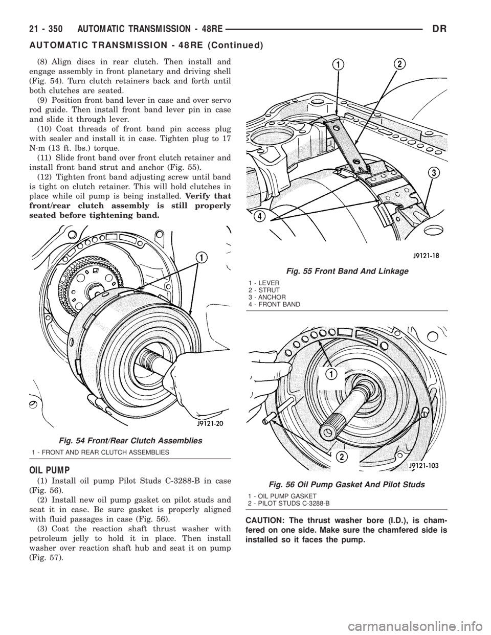
(8) Align discs in rear clutch. Then install and
engage assembly in front planetary and driving shell
(Fig. 54). Turn clutch retainers back and forth until
both clutches are seated.
(9) Position front band lever in case and over servo
rod guide. Then install front band lever pin in case
and slide it through lever.
(10) Coat threads of front band pin access plug
with sealer and install it in case. Tighten plug to 17
N´m (13 ft. lbs.) torque.
(11) Slide front band over front clutch retainer and
install front band strut and anchor (Fig. 55).
(12) Tighten front band adjusting screw until band
is tight on clutch retainer. This will hold clutches in
place while oil pump is being installed.Verify that
front/rear clutch assembly is still properly
seated before tightening band.
OIL PUMP
(1) Install oil pump Pilot Studs C-3288-B in case
(Fig. 56).
(2) Install new oil pump gasket on pilot studs and
seat it in case. Be sure gasket is properly aligned
with fluid passages in case (Fig. 56).
(3) Coat the reaction shaft thrust washer with
petroleum jelly to hold it in place. Then install
washer over reaction shaft hub and seat it on pump
(Fig. 57).CAUTION: The thrust washer bore (I.D.), is cham-
fered on one side. Make sure the chamfered side is
installed so it faces the pump.
Fig. 55 Front Band And Linkage
1 - LEVER
2 - STRUT
3 - ANCHOR
4 - FRONT BAND
Fig. 56 Oil Pump Gasket And Pilot Studs
1 - OIL PUMP GASKET
2 - PILOT STUDS C-3288-B
Fig. 54 Front/Rear Clutch Assemblies
1 - FRONT AND REAR CLUTCH ASSEMBLIES
21 - 350 AUTOMATIC TRANSMISSION - 48REDR
AUTOMATIC TRANSMISSION - 48RE (Continued)
Page 2223 of 2895
is equal on both sides of the dipstick. If one side is
noticably higher than the other, the dipstick has
picked up some oil from the dipstick tube. Allow the
oil to drain down the dipstick tube and re-check.
(7) Drive vehicle until transmission fluid is at nor-
mal operating temperature.
(8) With the engine running at curb idle speed, the
gear selector in NEUTRAL, and the parking brake
applied, check the transmission fluid level.
CAUTION: Do not overfill transmission, fluid foam-
ing and shifting problems can result.
(9)
Add fluid to bring level up to MAX arrow mark.
When fluid level is correct, shut engine off, release
park brake, remove funnel, and install dipstick in fill
tube.
FRONT CLUTCH
DESCRIPTION
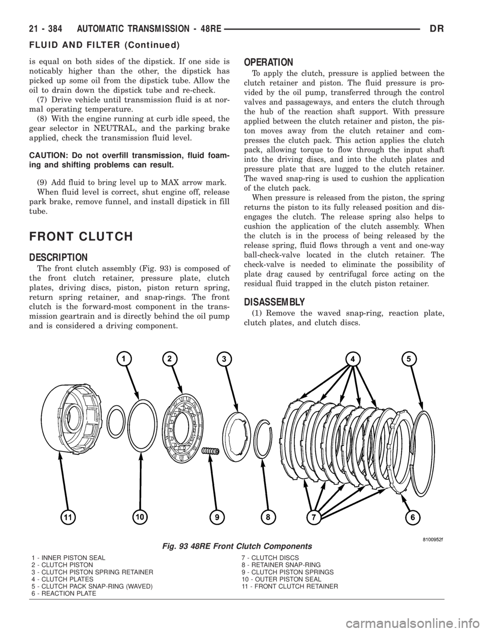
The front clutch assembly (Fig. 93) is composed of
the front clutch retainer, pressure plate, clutch
plates, driving discs, piston, piston return spring,
return spring retainer, and snap-rings. The front
clutch is the forward-most component in the trans-
mission geartrain and is directly behind the oil pump
and is considered a driving component.
OPERATION
To apply the clutch, pressure is applied between the
clutch retainer and piston. The fluid pressure is pro-
vided by the oil pump, transferred through the control
valves and passageways, and enters the clutch through
the hub of the reaction shaft support. With pressure
applied between the clutch retainer and piston, the pis-
ton moves away from the clutch retainer and com-
presses the clutch pack. This action applies the clutch
pack, allowing torque to flow through the input shaft
into the driving discs, and into the clutch plates and
pressure plate that are lugged to the clutch retainer.
The waved snap-ring is used to cushion the application
of the clutch pack.
When pressure is released from the piston, the spring
returns the piston to its fully released position and dis-
engages the clutch. The release spring also helps to
cushion the application of the clutch assembly. When
the clutch is in the process of being released by the
release spring, fluid flows through a vent and one-way
ball-check-valve located in the clutch retainer. The
check-valve is needed to eliminate the possibility of
plate drag caused by centrifugal force acting on the
residual fluid trapped in the clutch piston retainer.
DISASSEMBLY
(1) Remove the waved snap-ring, reaction plate,
clutch plates, and clutch discs.
Fig. 93 48RE Front Clutch Components
1 - INNER PISTON SEAL 7 - CLUTCH DISCS
2 - CLUTCH PISTON 8 - RETAINER SNAP-RING
3 - CLUTCH PISTON SPRING RETAINER 9 - CLUTCH PISTON SPRINGS
4 - CLUTCH PLATES 10 - OUTER PISTON SEAL
5 - CLUTCH PACK SNAP-RING (WAVED) 11 - FRONT CLUTCH RETAINER
6 - REACTION PLATE
21 - 384 AUTOMATIC TRANSMISSION - 48REDR
FLUID AND FILTER (Continued)
Page 2225 of 2895
Inspect the piston and retainer seal surfaces for
nicks or scratches. Minor scratches can be removed
with crocus cloth. However, replace the piston and/or
retainer if the seal surfaces are seriously scored.
Check the clutch piston check ball. The ball should
be securely in place. Replace the piston if the ball is
missing, or seized in place.
ASSEMBLY
NOTE: The 48RE transmission uses five plates and
discs for the front clutch.
(1) Soak clutch discs in transmission fluid.
(2) Install new inner piston seal onto the outer
diameter of the clutch retainer inner hub.
(3) Install new outer seal onto the clutch piston.
Be sure seal lips of both seals face the interior of the
retainer.
(4) Lubricate new inner and outer piston seals
with petroleum jelly.
(5) Install clutch piston in retainer. Use twisting
motion to seat piston in bottom of retainer. A thin
strip of plastic (about 0.015 - 0.020 in. thick), can be
used to guide seals into place if necessary.
CAUTION: Never push the clutch piston straight in.
This will fold the seals over causing leakage and
clutch slip. In addition, never use any type of metaltool to help ease the piston seals into place. Metal
tools will cut, shave, or score the seals.
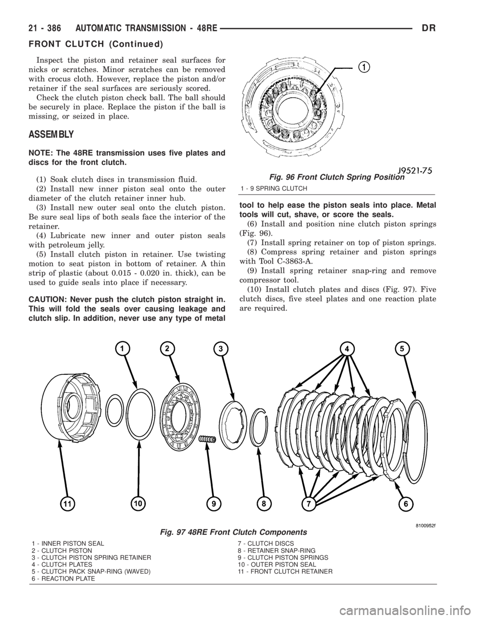
(6) Install and position nine clutch piston springs
(Fig. 96).
(7) Install spring retainer on top of piston springs.
(8) Compress spring retainer and piston springs
with Tool C-3863-A.
(9) Install spring retainer snap-ring and remove
compressor tool.
(10) Install clutch plates and discs (Fig. 97). Five
clutch discs, five steel plates and one reaction plate
are required.
Fig. 96 Front Clutch Spring Position
1 - 9 SPRING CLUTCH
Fig. 97 48RE Front Clutch Components
1 - INNER PISTON SEAL 7 - CLUTCH DISCS
2 - CLUTCH PISTON 8 - RETAINER SNAP-RING
3 - CLUTCH PISTON SPRING RETAINER 9 - CLUTCH PISTON SPRINGS
4 - CLUTCH PLATES 10 - OUTER PISTON SEAL
5 - CLUTCH PACK SNAP-RING (WAVED) 11 - FRONT CLUTCH RETAINER
6 - REACTION PLATE
21 - 386 AUTOMATIC TRANSMISSION - 48REDR
FRONT CLUTCH (Continued)
Page 2245 of 2895
able. Replace any of the overdrive unit snap-rings if
distorted or damaged.
Minor nicks or scratches on components can be
smoothed with crocus cloth. However, do not attempt
to reduce severe scoring on any components with
abrasive materials. Replace severely scored compo-
nents; do not try to salvage them.
INSPECTION
Check condition of the park lock components and
the overdrive case.
Check the bushings in the overdrive case. Replace
the bushings if severely scored or worn. Also replace
the case seal if loose, distorted, or damaged.
Examine the overdrive and direct clutch discs and
plates. Replace the discs if the facing is worn,
severely scored, or burned and flaking off. Replace
the clutch plates if worn, heavily scored, or cracked.
Check the lugs on the clutch plates for wear. The
plates should slide freely in the drum. Replace the
plates or drum if binding occurs.
Check condition of the annulus gear, direct clutch
hub, clutch drum and clutch spring. Replace the gear,
hub and drum if worn or damaged. Replace the
spring if collapsed, distorted, or cracked.
Be sure the splines and lugs on the gear, drum and
hub are in good condition. The clutch plates and
discs should slide freely in these components.
Inspect the thrust bearings and spring plate.
Replace the plate if worn or scored. Replace the bear-
ings if rough, noisy, brinnelled, or worn.
Inspect the planetary gear assembly and the sun
gear and bushings. If either the sun gear or the
bushings are damaged, replace the gear and bush-
ings as an assembly. The gear and bushings are not
serviced separately.
The planetary carrier and pinions must be in good
condition. Also be sure the pinion pins are secure and in
good condition. Replace the carrier if worn or damaged.
Inspect the overrunning clutch and race. The race
surface should be smooth and free of scores. Replace
the overrunning clutch assembly or the race if either
assembly is worn or damaged in any way.
Replace the shaft pilot bushing and inner bushing
if damaged. Replace either shaft bearing if rough or
noisy. Replace the bearing snap-rings if distorted or
cracked.
Check the machined surfaces on the output shaft.
These surfaces should clean and smooth. Very minor
nicks or scratches can be smoothed with crocus cloth.
Replace the shaft if worn, scored or damaged in any way.
Inspect the output shaft bushings. The small bush-
ing is the intermediate shaft pilot bushing. The large
bushing is the overrunning clutch hub bushing.
Replace either bushing if scored, pitted, cracked, or
worn.
ASSEMBLY
GEARTRAIN AND DIRECT CLUTCH
(1) Soak direct clutch and overdrive clutch discs in
MopartATF +4, Automatic Transmission fluid. Allow
discs to soak for 10-20 minutes.
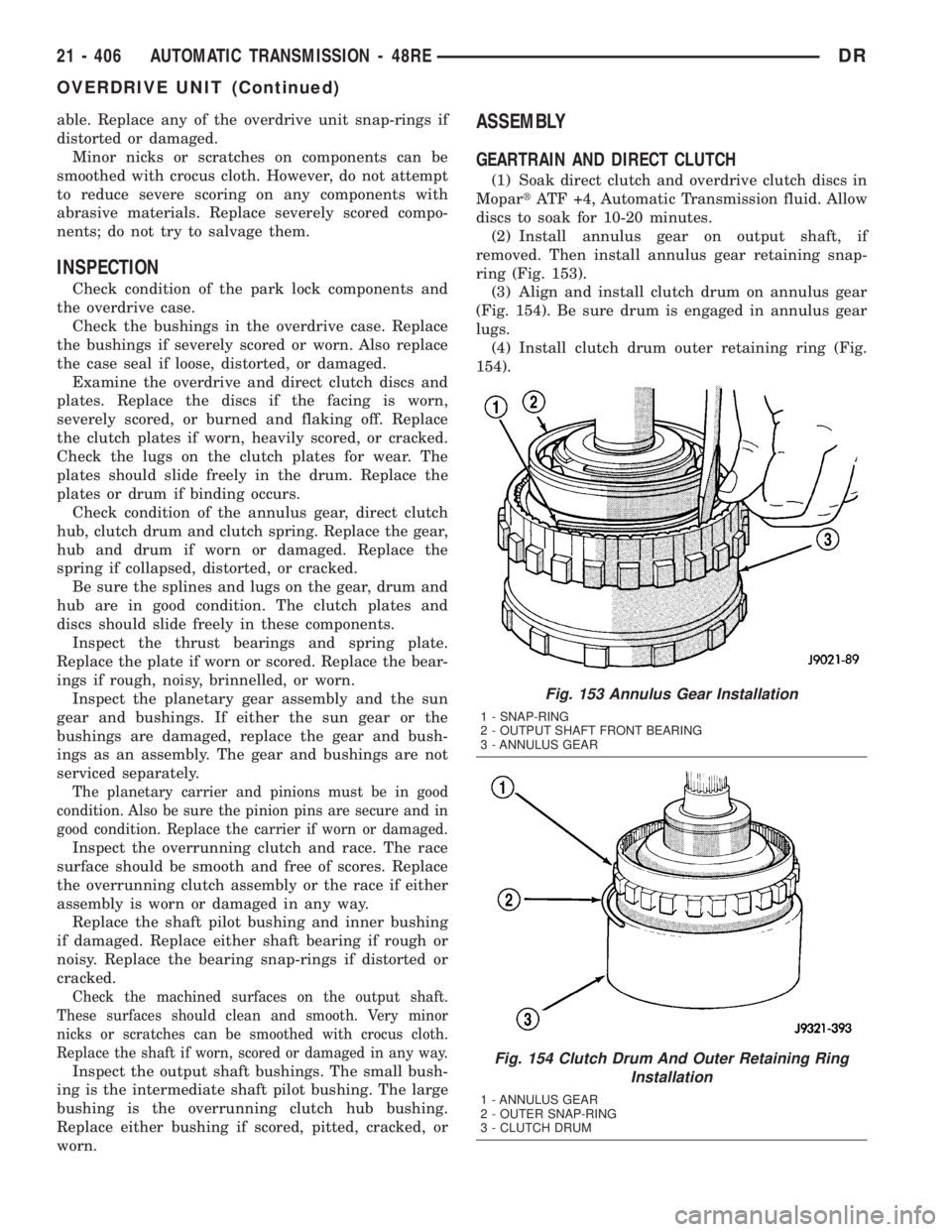
(2) Install annulus gear on output shaft, if
removed. Then install annulus gear retaining snap-
ring (Fig. 153).
(3) Align and install clutch drum on annulus gear
(Fig. 154). Be sure drum is engaged in annulus gear
lugs.
(4) Install clutch drum outer retaining ring (Fig.
154).
Fig. 153 Annulus Gear Installation
1 - SNAP-RING
2 - OUTPUT SHAFT FRONT BEARING
3 - ANNULUS GEAR
Fig. 154 Clutch Drum And Outer Retaining Ring
Installation
1 - ANNULUS GEAR
2 - OUTER SNAP-RING
3 - CLUTCH DRUM
21 - 406 AUTOMATIC TRANSMISSION - 48REDR
OVERDRIVE UNIT (Continued)
Page 2254 of 2895
ment Tool 6227-2. Overdrive unit cannot be installed
if splines are not aligned. If splines have rotated out
of alignment, unit will have to be disassembled to
realign splines.
(9)
Carefully slide Alignment Tool 6227-2 out of over-
drive planetary gear and overrunning clutch splines.
(10) Raise overdrive unit and carefully slide it
straight onto intermediate shaft. Insert park rod into
park lock reaction plug at same time. Avoid tilting
overdrive during installation as this could cause
planetary gear and overrunning clutch splines to
rotate out of alignment. If this occurs, it will be nec-
essary to remove and disassemble overdrive unit to
realign splines.
(11) Work overdrive unit forward on intermediate
shaft until seated against transmission case.
(12) Install bolts attaching overdrive unit to trans-
mission unit. Tighten bolts in diagonal pattern to 34
N´m (25 ft-lbs).
(13) Connect the transmission speed sensor and
overdrive wiring connectors.
(14) Install the transfer case, if equipped.
(15) Align and install rear propeller shaft, if nec-
essary. (Refer to 3 - DIFFERENTIAL & DRIVELINE/
PROPELLER SHAFT/PROPELLER SHAFT -
INSTALLATION)
OVERRUNNING CLUTCH
CAM/OVERDRIVE PISTON
RETAINER
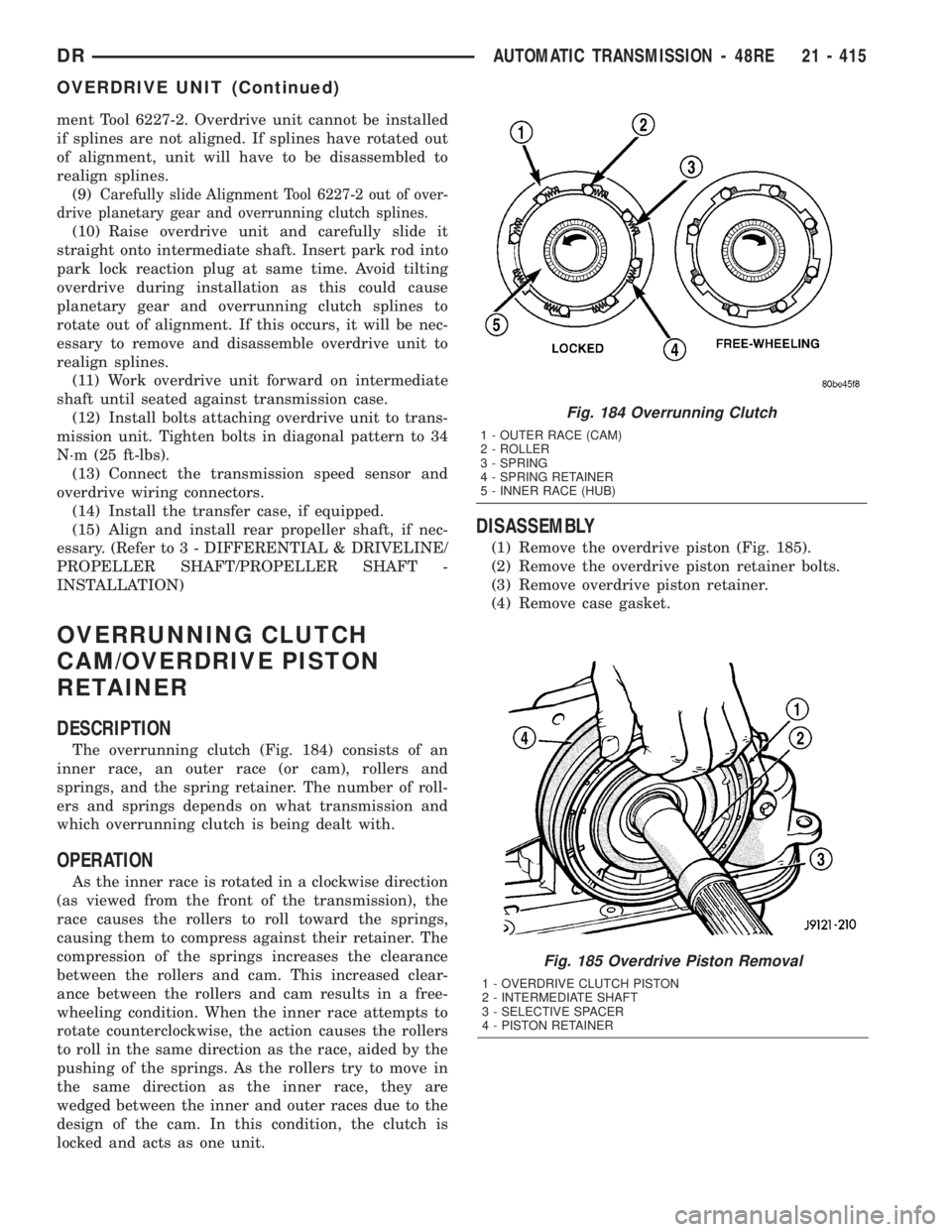
DESCRIPTION
The overrunning clutch (Fig. 184) consists of an
inner race, an outer race (or cam), rollers and
springs, and the spring retainer. The number of roll-
ers and springs depends on what transmission and
which overrunning clutch is being dealt with.
OPERATION
As the inner race is rotated in a clockwise direction
(as viewed from the front of the transmission), the
race causes the rollers to roll toward the springs,
causing them to compress against their retainer. The
compression of the springs increases the clearance
between the rollers and cam. This increased clear-
ance between the rollers and cam results in a free-
wheeling condition. When the inner race attempts to
rotate counterclockwise, the action causes the rollers
to roll in the same direction as the race, aided by the
pushing of the springs. As the rollers try to move in
the same direction as the inner race, they are
wedged between the inner and outer races due to the
design of the cam. In this condition, the clutch is
locked and acts as one unit.
DISASSEMBLY
(1) Remove the overdrive piston (Fig. 185).
(2) Remove the overdrive piston retainer bolts.
(3) Remove overdrive piston retainer.
(4) Remove case gasket.
Fig. 185 Overdrive Piston Removal
1 - OVERDRIVE CLUTCH PISTON
2 - INTERMEDIATE SHAFT
3 - SELECTIVE SPACER
4 - PISTON RETAINER
Fig. 184 Overrunning Clutch
1 - OUTER RACE (CAM)
2 - ROLLER
3 - SPRING
4 - SPRING RETAINER
5 - INNER RACE (HUB)
DRAUTOMATIC TRANSMISSION - 48RE 21 - 415
OVERDRIVE UNIT (Continued)
Page 2255 of 2895
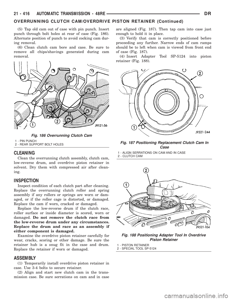
(5) Tap old cam out of case with pin punch. Insert
punch through bolt holes at rear of case (Fig. 186).
Alternate position of punch to avoid cocking cam dur-
ing removal.
(6) Clean clutch cam bore and case. Be sure to
remove all chips/shavings generated during cam
removal.
CLEANING
Clean the overrunning clutch assembly, clutch cam,
low-reverse drum, and overdrive piston retainer in
solvent. Dry them with compressed air after clean-
ing.
INSPECTION
Inspect condition of each clutch part after cleaning.
Replace the overrunning clutch roller and spring
assembly if any rollers or springs are worn or dam-
aged, or if the roller cage is distorted, or damaged.
Replace the cam if worn, cracked or damaged.
Replace the low-reverse drum if the clutch race,
roller surface or inside diameter is scored, worn or
damaged.Do not remove the clutch race from
the low-reverse drum under any circumstances.
Replace the drum and race as an assembly if
either component is damaged.
Examine the overdrive piston retainer carefully for
wear, cracks, scoring or other damage. Be sure the
retainer hub is a snug fit in the case and drum.
Replace the retainer if worn or damaged.
ASSEMBLY
(1) Temporarily install overdrive piston retainer in
case. Use 3-4 bolts to secure retainer.
(2) Align and start new clutch cam in the trans-
mission case. Be sure serrations on cam and in caseare aligned (Fig. 187). Then tap cam into case just
enough to hold it in place.
(3) Verify that cam is correctly positioned before
proceeding any further. Narrow ends of cam ramps
should be to left when cam is viewed from front end
of case (Fig. 187).
(4) Insert Adapter Tool SP-5124 into piston
retainer (Fig. 188).
Fig. 187 Positioning Replacement Clutch Cam In
Case
1 - ALIGN SERRATIONS ON CAM AND IN CASE
2 - CLUTCH CAM
Fig. 188 Positioning Adapter Tool In Overdrive
Piston Retainer
1 - PISTON RETAINER
2 - SPECIAL TOOL SP-5124
Fig. 186 Overrunning Clutch Cam
1 - PIN PUNCH
2 - REAR SUPPORT BOLT HOLES
21 - 416 AUTOMATIC TRANSMISSION - 48REDR
OVERRUNNING CLUTCH CAM/OVERDRIVE PISTON RETAINER (Continued)