2003 DODGE RAM Front hub assembly
[x] Cancel search: Front hub assemblyPage 2546 of 2895
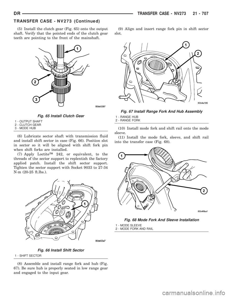
(5) Install the clutch gear (Fig. 65) onto the output
shaft. Verify that the pointed ends of the clutch gear
teeth are pointing to the front of the mainshaft.
(6) Lubricate sector shaft with transmission fluid
and install shift sector in case (Fig. 66). Position slot
in sector so it will be aligned with shift fork pin
when shift forks are installed.
(7) Apply LoctiteŸ 242, or equivalent, to the
threads of the sector support to replentish the factory
applied patch. Install the shift sector support.
Tighten the sector support with Socket 9033 to 27-34
N´m (20-25 ft.lbs.).
(8) Assemble and install range fork and hub (Fig.
67). Be sure hub is properly seated in low range gear
and engaged to the input gear.(9) Align and insert range fork pin in shift sector
slot.
(10) Install mode fork and shift rail onto the mode
sleeve.
(11) Install the mode fork, sleeve, and shift rail
into the transfer case (Fig. 68).
Fig. 65 Install Clutch Gear
1 - OUTPUT SHAFT
2 - CLUTCH GEAR
3 - MODE HUB
Fig. 66 Install Shift Sector
1 - SHIFT SECTOR
Fig. 67 Install Range Fork And Hub Assembly
1 - RANGE HUB
2 - RANGE FORK
Fig. 68 Mode Fork And Sleeve Installation
1 - MODE SLEEVE
2 - MODE FORK AND RAIL
DRTRANSFER CASE - NV273 21 - 707
TRANSFER CASE - NV273 (Continued)
Page 2560 of 2895
TIRES/WHEELS
TABLE OF CONTENTS
page page
TIRES/WHEELS
DIAGNOSIS AND TESTING - TIRE AND
WHEEL RUNOUT......................1
STANDARD PROCEDURE
STANDARD PROCEDURE - TIRE ROTATION . 2
STANDARD PROCEDURE - MATCH
MOUNTING...........................3
STANDARD PROCEDURE - TIRE AND
WHEEL BALANCE......................4
TIRES
DESCRIPTION
DESCRIPTION - SPARE TIRE /
TEMPORARY.........................5
DESCRIPTION - TIRES..................5
DESCRIPTION - RADIAL ± PLY TIRES......6
DESCRIPTION - TIRE PRESSURE FOR
HIGH SPEEDS.........................6
DESCRIPTION - REPLACEMENT TIRES.....6
DESCRIPTION - TIRE INFLATION
PRESSURES..........................6
DIAGNOSIS AND TESTING
DIAGNOSIS AND TESTING - PRESSURE
GAUGES.............................7
DIAGNOSIS AND TESTING - TIRE NOISE
OR VIBRATION........................7
DIAGNOSIS AND TESTING - TREAD WEAR
INDICATORS..........................7
DIAGNOSIS AND TESTING - TIRE WEAR
PATTERNS...........................8
DIAGNOSIS AND TESTING - TIRE/VEHICLE
LEAD................................8STANDARD PROCEDURE - REPAIRING
LEAKS..............................10
SPECIFICATIONS
TIRE REVOLUTIONS PER MILE..........10
WHEELS
DESCRIPTION.........................11
OPERATION...........................11
DIAGNOSIS AND TESTING
WHEEL INSPECTION..................11
STANDARD PROCEDURE
STANDARD PROCEDURE - WHEEL
REPLACEMENT.......................12
STANDARD PROCEDURE - DUAL REAR
WHEEL INSTALLATION.................12
SPECIFICATIONS
TORQUE CHART......................13
STUDS
REMOVAL.............................14
INSTALLATION.........................14
WHEEL COVER
REMOVAL.............................14
INSTALLATION
INSTALLATION - REAR.................14
INSTALLATION - FRONT................15
SPARE TIRE
DESCRIPTION
DESCRIPTION - SPARE / TEMPORARY
TIRE...............................15
DESCRIPTION - FULL SIZE, SPARE WHEEL
WITH MATCHING TIRE.................15
TIRES/WHEELS
DIAGNOSIS AND TESTING - TIRE AND WHEEL
RUNOUT
Radial runout is the difference between the high
and low points on the tire or wheel (Fig. 1).
Lateral runout is thewobbleof the tire or wheel.
Radial runout of more than 1.5 mm (.060 inch)
measured at the center line of the tread may cause
the vehicle to shake.
Lateral runout of more than 2.0 mm (.080 inch)
measured near the shoulder of the tire may cause the
vehicle to shake.
Sometimes radial runout can be reduced. Relocate
the wheel and tire assembly on the mounting studs
(See Method 1). If this does not reduce runout to anacceptable level, the tire can be rotated on the wheel.
(See Method 2).
METHOD 1 (RELOCATE WHEEL ON HUB)
(1) Drive vehicle a short distance to eliminate tire
flat spotting from a parked position.
(2) Check wheel bearings and adjust if adjustable
or replace if necessary.
(3) Check the wheel mounting surface.
(4) Relocate wheel on the mounting, two studs
over from the original position.
(5) Tighten wheel nuts until all are properly
torqued, to eliminate brake distortion.
(6) Check radial runout. If still excessive, mark
tire sidewall, wheel, and stud at point of maximum
runout and proceed to Method 2.
DRTIRES/WHEELS 22 - 1
Page 2573 of 2895
STUDS
REMOVAL
(1) Raise and support the vehicle.
(2) Remove the wheel and tire assembly.
(3) Remove the brake caliper, caliper adapter and
rotor, (Refer to 5 - BRAKES/HYDRAULIC/MECHAN-
ICAL/ROTORS - REMOVAL).
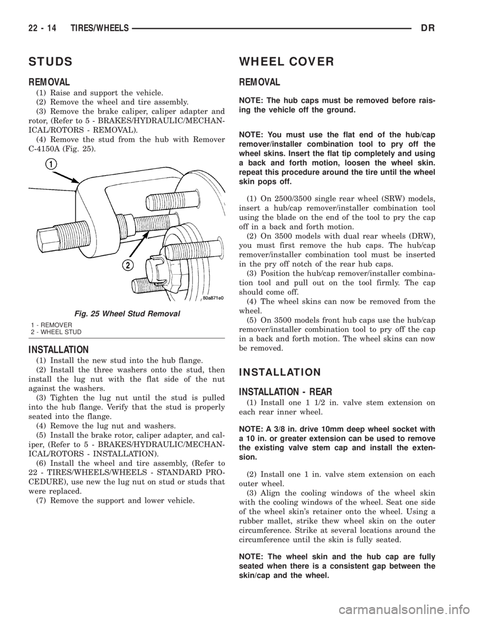
(4) Remove the stud from the hub with Remover
C-4150A (Fig. 25).
INSTALLATION
(1) Install the new stud into the hub flange.
(2) Install the three washers onto the stud, then
install the lug nut with the flat side of the nut
against the washers.
(3) Tighten the lug nut until the stud is pulled
into the hub flange. Verify that the stud is properly
seated into the flange.
(4) Remove the lug nut and washers.
(5) Install the brake rotor, caliper adapter, and cal-
iper, (Refer to 5 - BRAKES/HYDRAULIC/MECHAN-
ICAL/ROTORS - INSTALLATION).
(6) Install the wheel and tire assembly, (Refer to
22 - TIRES/WHEELS/WHEELS - STANDARD PRO-
CEDURE), use new the lug nut on stud or studs that
were replaced.
(7) Remove the support and lower vehicle.
WHEEL COVER
REMOVAL
NOTE: The hub caps must be removed before rais-
ing the vehicle off the ground.
NOTE: You must use the flat end of the hub/cap
remover/installer combination tool to pry off the
wheel skins. Insert the flat tip completely and using
a back and forth motion, loosen the wheel skin.
repeat this procedure around the tire until the wheel
skin pops off.
(1) On 2500/3500 single rear wheel (SRW) models,
insert a hub/cap remover/installer combination tool
using the blade on the end of the tool to pry the cap
off in a back and forth motion.
(2) On 3500 models with dual rear wheels (DRW),
you must first remove the hub caps. The hub/cap
remover/installer combination tool must be inserted
in the pry off notch of the rear hub caps.
(3) Position the hub/cap remover/installer combina-
tion tool and pull out on the tool firmly. The cap
should come off.
(4) The wheel skins can now be removed from the
wheel.
(5) On 3500 models front hub caps use the hub/cap
remover/installer combination tool to pry off the cap
in a back and forth motion. The wheel skins can now
be removed.
INSTALLATION
INSTALLATION - REAR
(1) Install one 1 1/2 in. valve stem extension on
each rear inner wheel.
NOTE: A 3/8 in. drive 10mm deep wheel socket with
a 10 in. or greater extension can be used to remove
the existing valve stem cap and install the exten-
sion.
(2) Install one 1 in. valve stem extension on each
outer wheel.
(3) Align the cooling windows of the wheel skin
with the cooling windows of the wheel. Seat one side
of the wheel skin's retainer onto the wheel. Using a
rubber mallet, strike thew wheel skin on the outer
circumference. Strike at several locations around the
circumference until the skin is fully seated.
NOTE: The wheel skin and the hub cap are fully
seated when there is a consistent gap between the
skin/cap and the wheel.
Fig. 25 Wheel Stud Removal
1 - REMOVER
2 - WHEEL STUD
22 - 14 TIRES/WHEELSDR
Page 2787 of 2895
INSPECTION
Examine the friction surfaces of the clutch rotor
and the clutch plate for wear. The rotor and clutch
plate should be replaced if there is excessive wear or
scoring.
If the friction surfaces are oily, inspect the shaft
and nose area of the compressor for oil. Remove the
felt from the front cover. If the felt is saturated with
oil, the shaft seal is leaking and the compressor must
be replaced.
Check the rotor bearing for roughness or excessive
leakage of grease. Replace the rotor and clutch plate,
if required.
INSTALLATION
(1) Install the clutch field coil and snap ring.
(2) Install the screw and retainer on the clutch coil
lead wire harness on the compressor front housing.
Tighten screw to 2.2 N´m (20 in. lbs.).
(3) Align the rotor assembly squarely on the front
compressor housing hub.
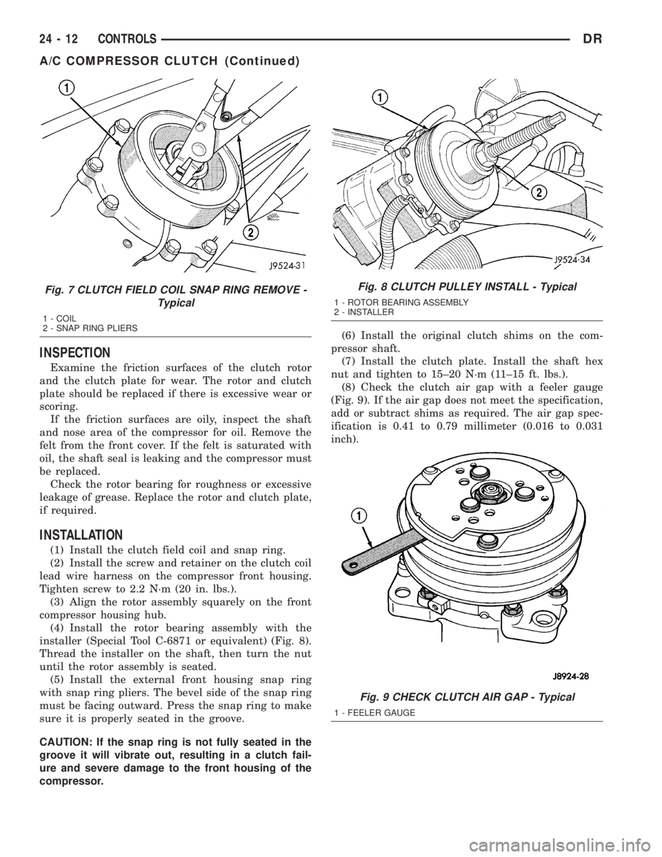
(4) Install the rotor bearing assembly with the
installer (Special Tool C-6871 or equivalent) (Fig. 8).
Thread the installer on the shaft, then turn the nut
until the rotor assembly is seated.
(5) Install the external front housing snap ring
with snap ring pliers. The bevel side of the snap ring
must be facing outward. Press the snap ring to make
sure it is properly seated in the groove.
CAUTION: If the snap ring is not fully seated in the
groove it will vibrate out, resulting in a clutch fail-
ure and severe damage to the front housing of the
compressor.(6) Install the original clutch shims on the com-
pressor shaft.
(7) Install the clutch plate. Install the shaft hex
nut and tighten to 15±20 N´m (11±15 ft. lbs.).
(8) Check the clutch air gap with a feeler gauge
(Fig. 9). If the air gap does not meet the specification,
add or subtract shims as required. The air gap spec-
ification is 0.41 to 0.79 millimeter (0.016 to 0.031
inch).
Fig. 7 CLUTCH FIELD COIL SNAP RING REMOVE -
Typical
1 - COIL
2 - SNAP RING PLIERS
Fig. 8 CLUTCH PULLEY INSTALL - Typical
1 - ROTOR BEARING ASSEMBLY
2 - INSTALLER
Fig. 9 CHECK CLUTCH AIR GAP - Typical
1 - FEELER GAUGE
24 - 12 CONTROLSDR
A/C COMPRESSOR CLUTCH (Continued)
Page 2872 of 2895
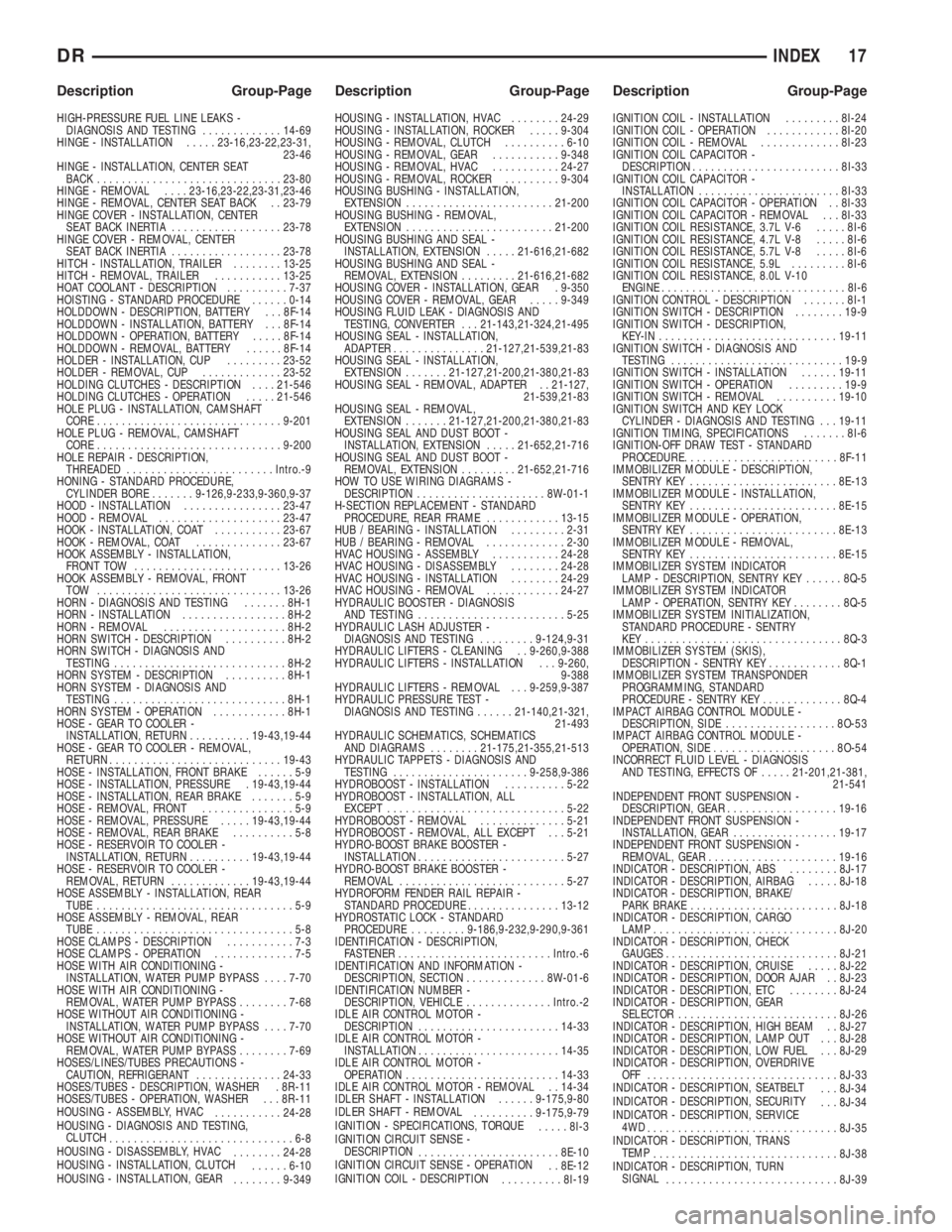
HIGH-PRESSURE FUEL LINE LEAKS -
DIAGNOSIS AND TESTING.............14-69
HINGE - INSTALLATION.....23-16,23-22,23-31,
23-46
HINGE - INSTALLATION, CENTER SEAT
BACK..............................23-80
HINGE - REMOVAL....23-16,23-22,23-31,23-46
HINGE - REMOVAL, CENTER SEAT BACK . . 23-79
HINGE COVER - INSTALLATION, CENTER
SEAT BACK INERTIA..................23-78
HINGE COVER - REMOVAL, CENTER
SEAT BACK INERTIA..................23-78
HITCH - INSTALLATION, TRAILER........13-25
HITCH - REMOVAL, TRAILER...........13-25
HOAT COOLANT - DESCRIPTION..........7-37
HOISTING - STANDARD PROCEDURE......0-14
HOLDDOWN - DESCRIPTION, BATTERY . . . 8F-14
HOLDDOWN - INSTALLATION, BATTERY . . . 8F-14
HOLDDOWN - OPERATION, BATTERY.....8F-14
HOLDDOWN - REMOVAL, BATTERY......8F-14
HOLDER - INSTALLATION, CUP.........23-52
HOLDER - REMOVAL, CUP.............23-52
HOLDING CLUTCHES - DESCRIPTION....21-546
HOLDING CLUTCHES - OPERATION.....21-546
HOLE PLUG - INSTALLATION, CAMSHAFT
CORE..............................9-201
HOLE PLUG - REMOVAL, CAMSHAFT
CORE..............................9-200
HOLE REPAIR - DESCRIPTION,
THREADED........................Intro.-9
HONING - STANDARD PROCEDURE,
CYLINDER BORE.......9-126,9-233,9-360,9-37
HOOD - INSTALLATION................23-47
HOOD - REMOVAL....................23-47
HOOK - INSTALLATION, COAT...........23-67
HOOK - REMOVAL, COAT..............23-67
HOOK ASSEMBLY - INSTALLATION,
FRONT TOW........................13-26
HOOK ASSEMBLY - REMOVAL, FRONT
TOW ..............................13-26
HORN - DIAGNOSIS AND TESTING.......8H-1
HORN - INSTALLATION.................8H-2
HORN - REMOVAL....................8H-2
HORN SWITCH - DESCRIPTION..........8H-2
HORN SWITCH - DIAGNOSIS AND
TESTING............................8H-2
HORN SYSTEM - DESCRIPTION..........8H-1
HORN SYSTEM - DIAGNOSIS AND
TESTING............................8H-1
HORN SYSTEM - OPERATION............8H-1
HOSE - GEAR TO COOLER -
INSTALLATION, RETURN..........19-43,19-44
HOSE - GEAR TO COOLER - REMOVAL,
RETURN............................19-43
HOSE - INSTALLATION, FRONT BRAKE......5-9
HOSE - INSTALLATION, PRESSURE . 19-43,19-44
HOSE - INSTALLATION, REAR BRAKE.......5-9
HOSE - REMOVAL, FRONT...............5-9
HOSE - REMOVAL, PRESSURE.....19-43,19-44
HOSE - REMOVAL, REAR BRAKE..........5-8
HOSE - RESERVOIR TO COOLER -
INSTALLATION, RETURN..........19-43,19-44
HOSE - RESERVOIR TO COOLER -
REMOVAL, RETURN.............19-43,19-44
HOSE ASSEMBLY - INSTALLATION, REAR
TUBE................................5-9
HOSE ASSEMBLY - REMOVAL, REAR
TUBE................................5-8
HOSE CLAMPS - DESCRIPTION...........7-3
HOSE CLAMPS - OPERATION.............7-5
HOSE WITH AIR CONDITIONING -
INSTALLATION, WATER PUMP BYPASS....7-70
HOSE WITH AIR CONDITIONING -
REMOVAL, WATER PUMP BYPASS........7-68
HOSE WITHOUT AIR CONDITIONING -
INSTALLATION, WATER PUMP BYPASS....7-70
HOSE WITHOUT AIR CONDITIONING -
REMOVAL, WATER PUMP BYPASS........7-69
HOSES/LINES/TUBES PRECAUTIONS -
CAUTION, REFRIGERANT..............24-33
HOSES/TUBES - DESCRIPTION, WASHER . 8R-11
HOSES/TUBES - OPERATION, WASHER . . . 8R-11
HOUSING - ASSEMBLY, HVAC
...........24-28
HOUSING - DIAGNOSIS AND TESTING,
CLUTCH
..............................6-8
HOUSING - DISASSEMBLY, HVAC
........24-28
HOUSING - INSTALLATION, CLUTCH
......6-10
HOUSING - INSTALLATION, GEAR
........9-349HOUSING - INSTALLATION, HVAC........24-29
HOUSING - INSTALLATION, ROCKER.....9-304
HOUSING - REMOVAL, CLUTCH..........6-10
HOUSING - REMOVAL, GEAR...........9-348
HOUSING - REMOVAL, HVAC...........24-27
HOUSING - REMOVAL, ROCKER.........9-304
HOUSING BUSHING - INSTALLATION,
EXTENSION........................21-200
HOUSING BUSHING - REMOVAL,
EXTENSION........................21-200
HOUSING BUSHING AND SEAL -
INSTALLATION, EXTENSION.....21-616,21-682
HOUSING BUSHING AND SEAL -
REMOVAL, EXTENSION.........21-616,21-682
HOUSING COVER - INSTALLATION, GEAR . 9-350
HOUSING COVER - REMOVAL, GEAR.....9-349
HOUSING FLUID LEAK - DIAGNOSIS AND
TESTING, CONVERTER . . . 21-143,21-324,21-495
HOUSING SEAL - INSTALLATION,
ADAPTER...............21-127,21-539,21-83
HOUSING SEAL - INSTALLATION,
EXTENSION.......21-127,21-200,21-380,21-83
HOUSING SEAL - REMOVAL, ADAPTER . . 21-127,
21-539,21-83
HOUSING SEAL - REMOVAL,
EXTENSION.......21-127,21-200,21-380,21-83
HOUSING SEAL AND DUST BOOT -
INSTALLATION, EXTENSION.....21-652,21-716
HOUSING SEAL AND DUST BOOT -
REMOVAL, EXTENSION.........21-652,21-716
HOW TO USE WIRING DIAGRAMS -
DESCRIPTION.....................8W-01-1
H-SECTION REPLACEMENT - STANDARD
PROCEDURE, REAR FRAME............13-15
HUB / BEARING - INSTALLATION.........2-31
HUB / BEARING - REMOVAL.............2-30
HVAC HOUSING - ASSEMBLY...........24-28
HVAC HOUSING - DISASSEMBLY........24-28
HVAC HOUSING - INSTALLATION........24-29
HVAC HOUSING - REMOVAL............24-27
HYDRAULIC BOOSTER - DIAGNOSIS
AND TESTING........................5-25
HYDRAULIC LASH ADJUSTER -
DIAGNOSIS AND TESTING.........9-124,9-31
HYDRAULIC LIFTERS - CLEANING . . 9-260,9-388
HYDRAULIC LIFTERS - INSTALLATION . . . 9-260,
9-388
HYDRAULIC LIFTERS - REMOVAL . . . 9-259,9-387
HYDRAULIC PRESSURE TEST -
DIAGNOSIS AND TESTING......21-140,21-321,
21-493
HYDRAULIC SCHEMATICS, SCHEMATICS
AND DIAGRAMS........21-175,21-355,21-513
HYDRAULIC TAPPETS - DIAGNOSIS AND
TESTING......................9-258,9-386
HYDROBOOST - INSTALLATION..........5-22
HYDROBOOST - INSTALLATION, ALL
EXCEPT.............................5-22
HYDROBOOST - REMOVAL..............5-21
HYDROBOOST - REMOVAL, ALL EXCEPT . . . 5-21
HYDRO-BOOST BRAKE BOOSTER -
INSTALLATION........................5-27
HYDRO-BOOST BRAKE BOOSTER -
REMOVAL...........................5-27
HYDROFORM FENDER RAIL REPAIR -
STANDARD PROCEDURE...............13-12
HYDROSTATIC LOCK - STANDARD
PROCEDURE.........9-186,9-232,9-290,9-361
IDENTIFICATION - DESCRIPTION,
FASTENER.........................Intro.-6
IDENTIFICATION AND INFORMATION -
DESCRIPTION, SECTION.............8W-01-6
IDENTIFICATION NUMBER -
DESCRIPTION, VEHICLE..............Intro.-2
IDLE AIR CONTROL MOTOR -
DESCRIPTION.......................14-33
IDLE AIR CONTROL MOTOR -
INSTALLATION.......................14-35
IDLE AIR CONTROL MOTOR -
OPERATION.........................14-33
IDLE AIR CONTROL MOTOR - REMOVAL . . 14-34
IDLER SHAFT - INSTALLATION......9-175,9-80
IDLER SHAFT - REMOVAL
..........9-175,9-79
IGNITION - SPECIFICATIONS, TORQUE
.....8I-3
IGNITION CIRCUIT SENSE -
DESCRIPTION
.......................8E-10
IGNITION CIRCUIT SENSE - OPERATION
. . 8E-12
IGNITION COIL - DESCRIPTION
..........8I-19IGNITION COIL - INSTALLATION.........8I-24
IGNITION COIL - OPERATION............8I-20
IGNITION COIL - REMOVAL.............8I-23
IGNITION COIL CAPACITOR -
DESCRIPTION........................8I-33
IGNITION COIL CAPACITOR -
INSTALLATION.......................8I-33
IGNITION COIL CAPACITOR - OPERATION . . 8I-33
IGNITION COIL CAPACITOR - REMOVAL . . . 8I-33
IGNITION COIL RESISTANCE, 3.7L V-6.....8I-6
IGNITION COIL RESISTANCE, 4.7L V-8.....8I-6
IGNITION COIL RESISTANCE, 5.7L V-8.....8I-6
IGNITION COIL RESISTANCE, 5.9L.........8I-6
IGNITION COIL RESISTANCE, 8.0L V-10
ENGINE..............................8I-6
IGNITION CONTROL - DESCRIPTION.......8I-1
IGNITION SWITCH - DESCRIPTION........19-9
IGNITION SWITCH - DESCRIPTION,
KEY-IN.............................19-11
IGNITION SWITCH - DIAGNOSIS AND
TESTING............................19-9
IGNITION SWITCH - INSTALLATION......19-11
IGNITION SWITCH - OPERATION.........19-9
IGNITION SWITCH - REMOVAL..........19-10
IGNITION SWITCH AND KEY LOCK
CYLINDER - DIAGNOSIS AND TESTING . . . 19-11
IGNITION TIMING, SPECIFICATIONS.......8I-6
IGNITION-OFF DRAW TEST - STANDARD
PROCEDURE..........................8F-11
IMMOBILIZER MODULE - DESCRIPTION,
SENTRY KEY........................8E-13
IMMOBILIZER MODULE - INSTALLATION,
SENTRY KEY........................8E-15
IMMOBILIZER MODULE - OPERATION,
SENTRY KEY........................8E-13
IMMOBILIZER MODULE - REMOVAL,
SENTRY KEY........................8E-15
IMMOBILIZER SYSTEM INDICATOR
LAMP - DESCRIPTION, SENTRY KEY......8Q-5
IMMOBILIZER SYSTEM INDICATOR
LAMP - OPERATION, SENTRY KEY........8Q-5
IMMOBILIZER SYSTEM INITIALIZATION,
STANDARD PROCEDURE - SENTRY
KEY................................8Q-3
IMMOBILIZER SYSTEM (SKIS),
DESCRIPTION - SENTRY KEY............8Q-1
IMMOBILIZER SYSTEM TRANSPONDER
PROGRAMMING, STANDARD
PROCEDURE - SENTRY KEY.............8Q-4
IMPACT AIRBAG CONTROL MODULE -
DESCRIPTION, SIDE..................8O-53
IMPACT AIRBAG CONTROL MODULE -
OPERATION, SIDE....................8O-54
INCORRECT FLUID LEVEL - DIAGNOSIS
AND TESTING, EFFECTS OF.....21-201,21-381,
21-541
INDEPENDENT FRONT SUSPENSION -
DESCRIPTION, GEAR..................19-16
INDEPENDENT FRONT SUSPENSION -
INSTALLATION, GEAR.................19-17
INDEPENDENT FRONT SUSPENSION -
REMOVAL, GEAR.....................19-16
INDICATOR - DESCRIPTION, ABS........8J-17
INDICATOR - DESCRIPTION, AIRBAG.....8J-18
INDICATOR - DESCRIPTION, BRAKE/
PARK BRAKE........................8J-18
INDICATOR - DESCRIPTION, CARGO
LAMP..............................8J-20
INDICATOR - DESCRIPTION, CHECK
GAUGES............................8J-21
INDICATOR - DESCRIPTION, CRUISE.....8J-22
INDICATOR - DESCRIPTION, DOOR AJAR . . 8J-23
INDICATOR - DESCRIPTION, ETC........8J-24
INDICATOR - DESCRIPTION, GEAR
SELECTOR..........................8J-26
INDICATOR - DESCRIPTION, HIGH BEAM . . 8J-27
INDICATOR - DESCRIPTION, LAMP OUT . . . 8J-28
INDICATOR - DESCRIPTION, LOW FUEL . . . 8J-29
INDICATOR - DESCRIPTION, OVERDRIVE
OFF ...............................8J-33
INDICATOR - DESCRIPTION, SEATBELT
. . . 8J-34
INDICATOR - DESCRIPTION, SECURITY
. . . 8J-34
INDICATOR - DESCRIPTION, SERVICE
4WD
...............................8J-35
INDICATOR - DESCRIPTION, TRANS
TEMP
..............................8J-38
INDICATOR - DESCRIPTION, TURN
SIGNAL
............................8J-39
DRINDEX 17
Description Group-Page Description Group-Page Description Group-Page