BODY CODE PLATE
DESCRIPTION
The Body Code Plate (Fig. 5) is located on the right
front hydroform fender rail just behind the headlight
assembly (Fig. 4). There are seven lines of informa-
tion on the body code plate. Lines 5, 6, and 7 are not
used to define service information. Information reads
from left to right, starting with line 4 in the center of
the plate to line 1 at the bottom of the plate.
The last code imprinted on a vehicle code plate will
be followed by the imprinted word END. When two
vehicle code plates are required, the last available
spaces on the first plate will be imprinted with the
letters CTD (for continued).
When a second vehicle code plate is necessary, the
first four spaces on each row will not be used because
of the plate overlap.
BODY CODE PLATEÐLINE 4
DIGITS 1 THROUGH 12
Vehicle Order Number
DIGITS 13, 14, AND 15
Transmission Codes
²DGT = 4±speed Automatic (46RE)
²DG4 = 4±speed Automatic (45RFE)
²DGP = 4±speed Automatic (47RE)
²DG8 = 4±speed Automatic (48RE)
²DDC = 5±speed Manual (NV3500)
²DDP = 5±speed Manual (NV4500)
²DEE = 6±speed Manual (NV5600)
DIGITS 16, 17, AND 18
Car Line Shell
²DR1=15004X2
²DR6=15004X4
²DR2=25004X2
²DR7=25004X4
²DR3=35004X2
²DR8=35004X4
Fig. 4 BODY CODE PLATE LOCATION
1 - FENDER
2 - RADIATOR CROSSMEMBER
3 - HYDROFORM FENDER RAIL
4 - RIVOT (2)
5 - BODY CODE PLATE
Fig. 5 BODY CODE PLATE
1 - PRIMARY PAINT
2 - SECONDARY PAINT
3 - TRANSMISSION CODE
4 - VEHICLE MODEL NUMBER
5 - ENGINE CODE
6 - INTERIOR TRIM CODE
7 - VEHICLE IDENTIFICATION NUMBER
8 - TAILGATE CODE
9 - CARGO BOX CODE
10 - TAILGATE TRIM CODE
11 - BODY-IN-WHITE SEQUENCE
12 - MARKET CODE
13 - SPECIES CODE
14 - PAINT PROCEDURE
15 - VEHICLE ORDER NUMBER
4 INTRODUCTIONDR
(5) Disconnect transmission oil lines from cooler.
Plug cooler lines to prevent oil leakage.
(6) Remove cooler bracket to transmission bolt.
(7) Remove two cooler bracket to cooler bolts.
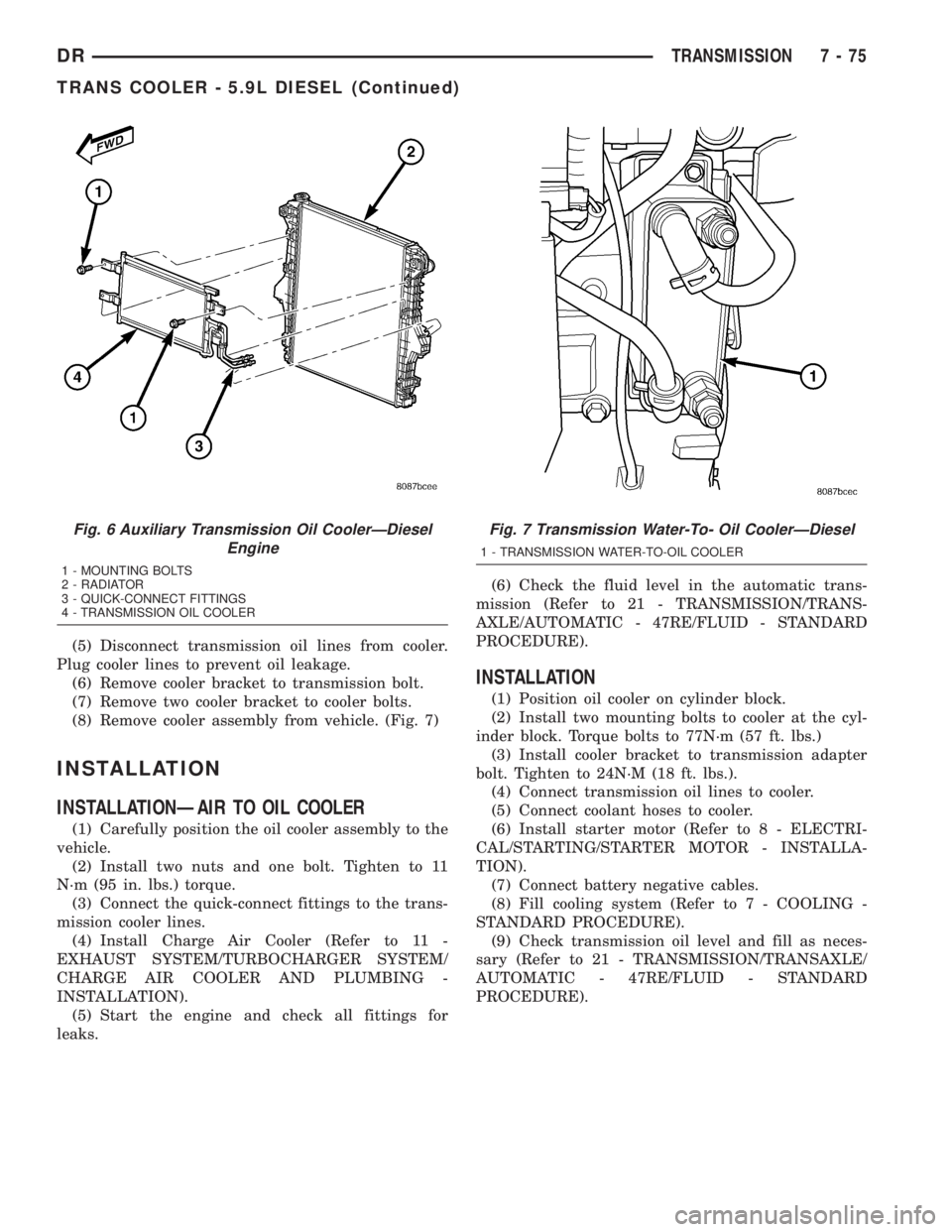
(8) Remove cooler assembly from vehicle. (Fig. 7)
INSTALLATION
INSTALLATIONÐAIR TO OIL COOLER
(1) Carefully position the oil cooler assembly to the
vehicle.
(2) Install two nuts and one bolt. Tighten to 11
N´m (95 in. lbs.) torque.
(3) Connect the quick-connect fittings to the trans-
mission cooler lines.
(4) Install Charge Air Cooler (Refer to 11 -
EXHAUST SYSTEM/TURBOCHARGER SYSTEM/
CHARGE AIR COOLER AND PLUMBING -
INSTALLATION).
(5) Start the engine and check all fittings for
leaks.(6) Check the fluid level in the automatic trans-
mission (Refer to 21 - TRANSMISSION/TRANS-
AXLE/AUTOMATIC - 47RE/FLUID - STANDARD
PROCEDURE).
INSTALLATION
(1) Position oil cooler on cylinder block.
(2) Install two mounting bolts to cooler at the cyl-
inder block. Torque bolts to 77N´m (57 ft. lbs.)
(3) Install cooler bracket to transmission adapter
bolt. Tighten to 24N´M (18 ft. lbs.).
(4) Connect transmission oil lines to cooler.
(5) Connect coolant hoses to cooler.
(6) Install starter motor (Refer to 8 - ELECTRI-
CAL/STARTING/STARTER MOTOR - INSTALLA-
TION).
(7) Connect battery negative cables.
(8) Fill cooling system (Refer to 7 - COOLING -
STANDARD PROCEDURE).
(9) Check transmission oil level and fill as neces-
sary (Refer to 21 - TRANSMISSION/TRANSAXLE/
AUTOMATIC - 47RE/FLUID - STANDARD
PROCEDURE).
Fig. 6 Auxiliary Transmission Oil CoolerÐDiesel
Engine
1 - MOUNTING BOLTS
2 - RADIATOR
3 - QUICK-CONNECT FITTINGS
4 - TRANSMISSION OIL COOLER
Fig. 7 Transmission Water-To- Oil CoolerÐDiesel
1 - TRANSMISSION WATER-TO-OIL COOLER
DRTRANSMISSION 7 - 75
TRANS COOLER - 5.9L DIESEL (Continued)