2003 DODGE RAM wheel
[x] Cancel search: wheelPage 1 of 2895

GROUP TAB LOCATOR
Introduction
0Lubrication & Maintenance
2Suspension
3Differential & Driveline
5Brakes
6Clutch
7Cooling
8AAudio
8BChime/Buzzer
8EElectronic Control Modules
8FEngine Systems
8GHeated Systems
8HHorn
8IIgnition Control
8JInstrument Cluster
8LLamps
8MMessage Systems
8NPower Systems
8ORestraints
8PSpeed Control
8QVehicle Theft Security
8RWipers/Washers
8WWiring
9Engine
11Exhaust System
13Frame & Bumpers
14Fuel System
19Steering
21Transmission and Transfer Case
22Tires/Wheels
23Body
24Heating & Air Conditioning
25Emissions Control
Component and System Index
Service Manual Comment Forms (Rear of Manual)
Page 2 of 2895

INTRODUCTION
TABLE OF CONTENTS
page page
VEHICLE SAFETY CERTIFICATION LABEL
DESCRIPTION..........................1
VEHICLE IDENTIFICATION NUMBER
DESCRIPTION..........................2
VEHICLE EMISSION CONTROL INFORMATION
(VECI)
DESCRIPTION..........................3
BODY CODE PLATE
DESCRIPTION..........................4
INTERNATIONAL VEHICLE CONTROL &
DISPLAY SYMBOLS
DESCRIPTION - INTERNATIONAL SYMBOLS . . . 6FASTENER IDENTIFICATION
DESCRIPTION..........................6
FASTENER USAGE
DESCRIPTION - FASTENER USAGE.........9
THREADED HOLE REPAIR
DESCRIPTION - THREADED HOLE REPAIR....9
METRIC SYSTEM
DESCRIPTION..........................9
TORQUE REFERENCES
DESCRIPTION.........................11
VEHICLE SAFETY
CERTIFICATION LABEL
DESCRIPTION
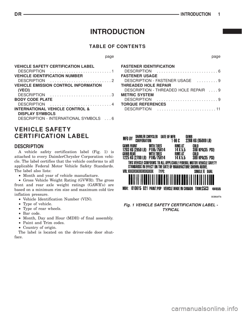
A vehicle safety certification label (Fig. 1) is
attached to every DaimlerChrysler Corporation vehi-
cle. The label certifies that the vehicle conforms to all
applicable Federal Motor Vehicle Safety Standards.
The label also lists:
²Month and year of vehicle manufacture.
²Gross Vehicle Weight Rating (GVWR). The gross
front and rear axle weight ratings (GAWR's) are
based on a minimum rim size and maximum cold tire
inflation pressure.
²Vehicle Identification Number (VIN).
²Type of vehicle.
²Type of rear wheels.
²Bar code.
²Month, Day and Hour (MDH) of final assembly.
²Paint and Trim codes.
²Country of origin.
The label is located on the driver-side door shut-
face.
Fig. 1 VEHICLE SAFETY CERTIFICATION LABEL -
TYPICAL
DRINTRODUCTION 1
Page 3 of 2895

VEHICLE IDENTIFICATION
NUMBER
DESCRIPTION
VIN CODING/LOCATIONS
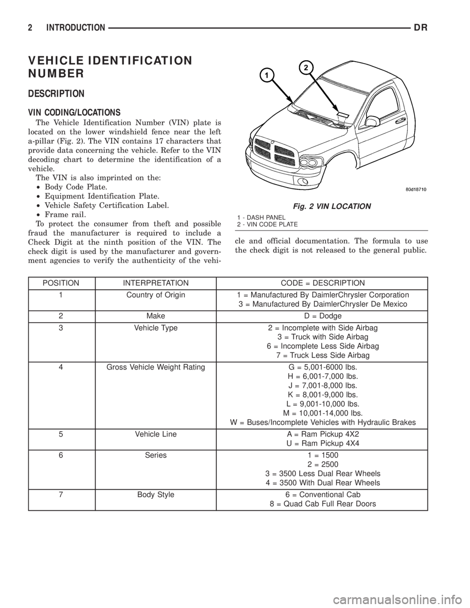
The Vehicle Identification Number (VIN) plate is
located on the lower windshield fence near the left
a-pillar (Fig. 2). The VIN contains 17 characters that
provide data concerning the vehicle. Refer to the VIN
decoding chart to determine the identification of a
vehicle.
The VIN is also imprinted on the:
²Body Code Plate.
²Equipment Identification Plate.
²Vehicle Safety Certification Label.
²Frame rail.
To protect the consumer from theft and possible
fraud the manufacturer is required to include a
Check Digit at the ninth position of the VIN. The
check digit is used by the manufacturer and govern-
ment agencies to verify the authenticity of the vehi-cle and official documentation. The formula to use
the check digit is not released to the general public.
POSITION INTERPRETATION CODE = DESCRIPTION
1 Country of Origin 1 = Manufactured By DaimlerChrysler Corporation
3 = Manufactured By DaimlerChrysler De Mexico
2 Make D = Dodge
3 Vehicle Type 2 = Incomplete with Side Airbag
3 = Truck with Side Airbag
6 = Incomplete Less Side Airbag
7 = Truck Less Side Airbag
4 Gross Vehicle Weight Rating G = 5,001-6000 lbs.
H = 6,001-7,000 lbs.
J = 7,001-8,000 lbs.
K = 8,001-9,000 lbs.
L = 9,001-10,000 lbs.
M = 10,001-14,000 lbs.
W = Buses/Incomplete Vehicles with Hydraulic Brakes
5 Vehicle Line A = Ram Pickup 4X2
U = Ram Pickup 4X4
6 Series 1 = 1500
2 = 2500
3 = 3500 Less Dual Rear Wheels
4 = 3500 With Dual Rear Wheels
7 Body Style 6 = Conventional Cab
8 = Quad Cab Full Rear Doors
Fig. 2 VIN LOCATION
1 - DASH PANEL
2 - VIN CODE PLATE
2 INTRODUCTIONDR
Page 15 of 2895

Diesel fuel is seldom completely free of water. To
prevent fuel system trouble, including fuel line freez-
ing in winter, drain the accumulated water from the
fuel/water separator using the fuel/water separator
drain provided. If you buy good-quality fuel and fol-
low the cold-weather advice above, fuel conditioners
should not be required in your vehicle. If available in
your area, a high cetane ªpremiumº diesel fuel may
offer improved cold starting and warm-up perfor-
mance.
DESCRIPTION - ENGINE OIL AND LUBRICANTS
WARNING: NEW OR USED ENGINE OIL CAN BE
IRRITATING TO THE SKIN. AVOID PROLONGED OR
REPEATED SKIN CONTACT WITH ENGINE OIL.
CONTAMINANTS IN USED ENGINE OIL, CAUSED BY
INTERNAL COMBUSTION, CAN BE HAZARDOUS TO
YOUR HEALTH. THOROUGHLY WASH EXPOSED
SKIN WITH SOAP AND WATER. DO NOT WASH
SKIN WITH GASOLINE, DIESEL FUEL, THINNER, OR
SOLVENTS, HEALTH PROBLEMS CAN RESULT. DO
NOT POLLUTE, DISPOSE OF USED ENGINE OIL
PROPERLY. CONTACT YOUR DEALER OR GOVERN-
MENT AGENCY FOR LOCATION OF COLLECTION
CENTER IN YOUR AREA.
When service is required, DaimlerChrysler Corpo-
ration recommends that only Mopartbrand parts,
lubricants and chemicals be used. Mopartprovides
the best engineered products for servicing
DaimlerChrysler Corporation vehicles.
Only lubricants bearing designations defined by
the following organization should be used.
²Society of Automotive Engineers (SAE)
²American Petroleum Institute (API)
²National Lubricating Grease Institute (NLGI)
API SERVICE GRADE CERTIFIED
Use an engine oil that is API Certified. MOPARt
provides engine oils, that meet or exceed this
requirement.
SAE VISCOSITY
An SAE viscosity grade is used to specify the vis-
cosity of engine oil. Use only engine oils with multi-
ple viscosities such as 5W-30 or 10W-30. These are
specified with a dual SAE viscosity grade which indi-
cates the cold-to-hot temperature viscosity range.
Select an engine oil that is best suited to your par-
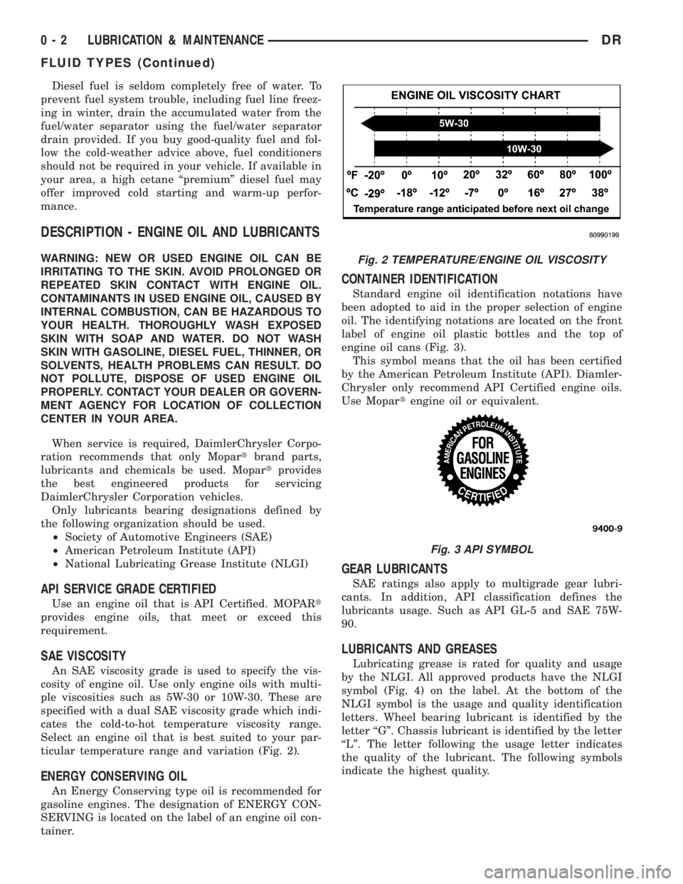
ticular temperature range and variation (Fig. 2).
ENERGY CONSERVING OIL
An Energy Conserving type oil is recommended for
gasoline engines. The designation of ENERGY CON-
SERVING is located on the label of an engine oil con-
tainer.
CONTAINER IDENTIFICATION
Standard engine oil identification notations have
been adopted to aid in the proper selection of engine
oil. The identifying notations are located on the front
label of engine oil plastic bottles and the top of
engine oil cans (Fig. 3).
This symbol means that the oil has been certified
by the American Petroleum Institute (API). Diamler-
Chrysler only recommend API Certified engine oils.
Use Mopartengine oil or equivalent.
GEAR LUBRICANTS
SAE ratings also apply to multigrade gear lubri-
cants. In addition, API classification defines the
lubricants usage. Such as API GL-5 and SAE 75W-
90.
LUBRICANTS AND GREASES
Lubricating grease is rated for quality and usage
by the NLGI. All approved products have the NLGI
symbol (Fig. 4) on the label. At the bottom of the
NLGI symbol is the usage and quality identification
letters. Wheel bearing lubricant is identified by the
letter ªGº. Chassis lubricant is identified by the letter
ªLº. The letter following the usage letter indicates
the quality of the lubricant. The following symbols
indicate the highest quality.
Fig. 2 TEMPERATURE/ENGINE OIL VISCOSITY
Fig. 3 API SYMBOL
0 - 2 LUBRICATION & MAINTENANCEDR
FLUID TYPES (Continued)
Page 16 of 2895

SPECIALIZED LUBRICANTS AND OILS
Some maintenance or repair procedures may
require the use of specialized lubricants or oils. Con-
sult the appropriate sections in this manual for the
correct application of these lubricants.
DESCRIPTION - POWER STEERING FLUID
MopartATF +4, Automatic Transmission Fluid is
required in the power steering system. Substitute
fluids can induce power steering system failure.
MopartATF +4, Automatic Transmission Fluid
when new is red in color. The ATF is dyed red so it
can be identified from other fluids used in the vehicle
such as engine oil or antifreeze. The red color is not
permanent and is not an indicator of fluid condition.
As the vehicle is driven, the ATF will begin to look
darker in color and may eventually become brown.
This is normal.ATF+4 also has a unique odor that
may change with age. Consequently, odor and color
cannot be used to indicate the fluid condition or the
need for a fluid change.
DESCRIPTION - ENGINE COOLANT
WARNING: ANTIFREEZE IS AN ETHYLENE GLYCOL
BASE COOLANT AND IS HARMFUL IF SWAL-
LOWED OR INHALED. IF SWALLOWED, DRINK
TWO GLASSES OF WATER AND INDUCE VOMIT-
ING. IF INHALED, MOVE TO FRESH AIR AREA.
SEEK MEDICAL ATTENTION IMMEDIATELY. DO NOT
STORE IN OPEN OR UNMARKED CONTAINERS.
WASH SKIN AND CLOTHING THOROUGHLY AFTER
COMING IN CONTACT WITH ETHYLENE GLYCOL.
KEEP OUT OF REACH OF CHILDREN. DISPOSE OF
GLYCOL BASE COOLANT PROPERLY, CONTACT
YOUR DEALER OR GOVERNMENT AGENCY FOR
LOCATION OF COLLECTION CENTER IN YOUR
AREA. DO NOT OPEN A COOLING SYSTEM WHEN
THE ENGINE IS AT OPERATING TEMPERATURE OR
HOT UNDER PRESSURE, PERSONAL INJURY CAN
RESULT. AVOID RADIATOR COOLING FAN WHENENGINE COMPARTMENT RELATED SERVICE IS
PERFORMED, PERSONAL INJURY CAN RESULT.
CAUTION: Use of Propylene Glycol based coolants
is not recommended, as they provide less freeze
protection and less corrosion protection.
The cooling system is designed around the coolant.
The coolant must accept heat from engine metal, in
the cylinder head area near the exhaust valves and
engine block. Then coolant carries the heat to the
radiator where the tube/fin radiator can transfer the
heat to the air.
The use of aluminum cylinder blocks, cylinder
heads, and water pumps requires special corrosion
protection. MopartAntifreeze/Coolant, 5
Year/100,000 Mile Formula (MS-9769), or the equiva-
lent ethylene glycol base coolant with organic corro-
sion inhibitors (called HOAT, for Hybrid Organic
Additive Technology) is recommended. This coolant
offers the best engine cooling without corrosion when
mixed with 50% Ethylene Glycol and 50% distilled
water to obtain a freeze point of -37ÉC (-35ÉF). If it
loses color or becomes contaminated, drain, flush,
and replace with fresh properly mixed coolant solu-
tion.
CAUTION: MoparTAntifreeze/Coolant, 5
Year/100,000 Mile Formula (MS-9769) may not be
mixed with any other type of antifreeze. Mixing of
coolants other than specified (non-HOAT or other
HOAT), may result in engine damage that may not
be covered under the new vehicle warranty, and
decreased corrosion protection.
COOLANT PERFORMANCE
The required ethylene-glycol (antifreeze) and water
mixture depends upon climate and vehicle operating
conditions. The coolant performance of various mix-
tures follows:
Pure Water-Water can absorb more heat than a
mixture of water and ethylene-glycol. This is for pur-
pose of heat transfer only. Water also freezes at a
higher temperature and allows corrosion.
100 percent Ethylene-Glycol-The corrosion
inhibiting additives in ethylene-glycol need the pres-
ence of water to dissolve. Without water, additives
form deposits in system. These act as insulation
causing temperature to rise to as high as 149ÉC
(300ÉF). This temperature is hot enough to melt plas-
tic and soften solder. The increased temperature can
result in engine detonation. In addition, 100 percent
ethylene-glycol freezes at -22ÉC (-8ÉF).
50/50 Ethylene-Glycol and Water-Is the recom-
mended mixture, it provides protection against freez-
ing to -37ÉC (-34ÉF). The antifreeze concentration
Fig. 4 NLGI SYMBOL
1 - WHEEL BEARINGS
2 - CHASSIS LUBRICATION
3 - CHASSIS AND WHEEL BEARINGS
DRLUBRICATION & MAINTENANCE 0 - 3
FLUID TYPES (Continued)
Page 28 of 2895

TOWING
STANDARD PROCEDURE - TOWING
A vehicle equipped with SAE approved sling-type
towing equipment can be used to tow all vehicles.
When towing a 4WD vehicle using a wheel-lift towing
device, use tow dollies under the opposite end of the
vehicle. A vehicle with flat-bed device can also be
used to transport a disabled vehicle (Fig. 9).
A wooden crossbeam may be required for proper
connection when using the sling-type, front-end tow-
ing method.
SAFETY PRECAUTIONS
CAUTION: The following safety precautions must be
observed when towing a vehicle:
²Secure loose and protruding parts.
²Always use a safety chain system that is inde-
pendent of the lifting and towing equipment.
²Do not allow towing equipment to contact the
disabled vehicle's fuel tank.
²Do not allow anyone under the disabled vehicle
while it is lifted by the towing device.
²Do not allow passengers to ride in a vehicle
being towed.
²Always observe state and local laws regarding
towing regulations.
²Do not tow a vehicle in a manner that could
jeopardize the safety of the operator, pedestrians or
other motorists.
²Do not attach tow chains, T-hooks, J-hooks, or a
tow sling to a bumper, steering linkage, drive shafts
or a non-reinforced frame hole.
²Do not tow a heavily loaded vehicle. Damage to
the cab, cargo box or frame may result. Use a flatbed
device to transport a loaded vehicle.
GROUND CLEARANCE
CAUTION: If vehicle is towed with wheels removed,
install lug nuts to retain brake drums or rotors.
Fig. 7 FRONT LIFT PAD LOCATION
1 - BODY MOUNT BRACKET
2 - FRONT LIFT PAD
3 - TRANSMISSION CROSSMEMBER BRACKET
4 - FRAME RAIL
Fig. 8 REAR LIFT PAD LOCATION
1 - FRAME RAIL
2 - REAR LIFT PAD
3 - LEAF SPRING MOUNTING BRACKET
4 - BOX MOUNTING BRACKET
Fig. 9 Tow Vehicles With Approved Equipment
1 - SLING TYPE2 - WHEEL LIFT3 - FLAT BED
DRLUBRICATION & MAINTENANCE 0 - 15
HOISTING (Continued)
Page 29 of 2895

A towed vehicle should be raised until lifted wheels
are a minimum 100 mm (4 in) from the ground. Be
sure there is adequate ground clearance at the oppo-
site end of the vehicle, especially when towing over
rough terrain or steep rises in the road. If necessary,
remove the wheels from the lifted end of the vehicle
and lower the vehicle closer to the ground, to
increase the ground clearance at the opposite end of
the vehicle. Install lug nuts on wheel attaching studs
to retain brake drums or rotors.
RAMP ANGLE
If a vehicle with flat-bed towing equipment is used,
the approach ramp angle should not exceed 15
degrees.
TOWING WHEN KEYS ARE NOT AVAILABLE
When the vehicle is locked and keys are not avail-
able, use a flat bed hauler. A Wheel-lift or Sling-type
device can be used on 4WD vehicles providedall the
wheels are lifted off the ground using tow dol-
lies.
FOUR-WHEEL-DRIVE VEHICLE TOWING
Chrysler Corporation recommends that a vehicle be
transported on a flat-bed device. A Wheel-lift or
Sling-type device can be used providedall the
wheels are lifted off the ground using tow dol-
lies.
WARNING: WHEN TOWING A DISABLED VEHICLE
AND THE DRIVE WHEELS ARE SECURED IN A
WHEEL LIFT OR TOW DOLLIES, ENSURE THE
TRANSMISSION IS IN THE PARK POSITION (AUTO-
MATIC TRANSMISSION) OR A FORWARD DRIVE
GEAR (MANUAL TRANSMISSION).
CAUTION: Many vehicles are equipped with air
dams, spoilers, and/or ground effect panels. To
avoid component damage, a wheel-lift towing vehi-
cle or a flat-bed hauling vehicle is recommended.
0 - 16 LUBRICATION & MAINTENANCEDR
TOWING (Continued)
Page 30 of 2895

SUSPENSION
TABLE OF CONTENTS
page page
WHEEL ALIGNMENT......................1
FRONT - INDEPENDENT FRONT SUSPENSION..8FRONT - LINK/COIL......................28
REAR.................................38
WHEEL ALIGNMENT
TABLE OF CONTENTS
page page
WHEEL ALIGNMENT
DESCRIPTION..........................1
OPERATION............................2
DIAGNOSIS AND TESTING - PRE-ALIGNMENT
INSPECTION..........................2
STANDARD PROCEDURE
STANDARD PROCEDURE - HEIGHT
MEASUREMENT - 4WD (LD)..............3
STANDARD PROCEDURE - HEIGHT
ADJUSTMENT - 4WD (LD)................3
STANDARD PROCEDURE - CAMBER AND
CASTER ADJUSTMENT..................4STANDARD PROCEDURE - TOE
ADJUSTMENT.........................4
STANDARD PROCEDURE - CAMBER,
CASTER AND TOE ADJUSTMENT..........4
STANDARD PROCEDURE - ALIGNMENT
LINK/COIL SUSPENSION.................5
SPECIFICATIONS
ALIGNMENT..........................6
SPECIAL TOOLS
WHEEL ALIGNMENT....................7
WHEEL ALIGNMENT
DESCRIPTION
NOTE: Suspension components with rubber/ure-
thane bushings should be tightened with the vehi-
cle at normal ride height. It is important to have the
springs supporting the weight of the vehicle when
the fasteners are torqued. If springs are not at their
normal ride position, vehicle ride comfort could be
affected and premature bushing wear may occur.
Wheel alignment involves the correct positioning of
the wheels in relation to the vehicle. The positioning
is accomplished through suspension and steering
linkage adjustments. An alignment is considered
essential for efficient steering, good directional stabil-
ity and to minimize tire wear. The most important
measurements of an alignment are caster, camber
and toe (Fig. 1).
CAUTION: Never attempt to modify suspension or
steering components by heating or bending.
Fig. 1 Wheel Alignment Measurements
1 - FRONT OF VEHICLE
2 - STEERING AXIS INCLINATION
3 - PIVOT POINT
4 - TOE-IN
DRSUSPENSION 2 - 1