2003 DODGE RAM oil additives
[x] Cancel search: oil additivesPage 16 of 2895

SPECIALIZED LUBRICANTS AND OILS
Some maintenance or repair procedures may
require the use of specialized lubricants or oils. Con-
sult the appropriate sections in this manual for the
correct application of these lubricants.
DESCRIPTION - POWER STEERING FLUID
MopartATF +4, Automatic Transmission Fluid is
required in the power steering system. Substitute
fluids can induce power steering system failure.
MopartATF +4, Automatic Transmission Fluid
when new is red in color. The ATF is dyed red so it
can be identified from other fluids used in the vehicle
such as engine oil or antifreeze. The red color is not
permanent and is not an indicator of fluid condition.
As the vehicle is driven, the ATF will begin to look
darker in color and may eventually become brown.
This is normal.ATF+4 also has a unique odor that
may change with age. Consequently, odor and color
cannot be used to indicate the fluid condition or the
need for a fluid change.
DESCRIPTION - ENGINE COOLANT
WARNING: ANTIFREEZE IS AN ETHYLENE GLYCOL
BASE COOLANT AND IS HARMFUL IF SWAL-
LOWED OR INHALED. IF SWALLOWED, DRINK
TWO GLASSES OF WATER AND INDUCE VOMIT-
ING. IF INHALED, MOVE TO FRESH AIR AREA.
SEEK MEDICAL ATTENTION IMMEDIATELY. DO NOT
STORE IN OPEN OR UNMARKED CONTAINERS.
WASH SKIN AND CLOTHING THOROUGHLY AFTER
COMING IN CONTACT WITH ETHYLENE GLYCOL.
KEEP OUT OF REACH OF CHILDREN. DISPOSE OF
GLYCOL BASE COOLANT PROPERLY, CONTACT
YOUR DEALER OR GOVERNMENT AGENCY FOR
LOCATION OF COLLECTION CENTER IN YOUR
AREA. DO NOT OPEN A COOLING SYSTEM WHEN
THE ENGINE IS AT OPERATING TEMPERATURE OR
HOT UNDER PRESSURE, PERSONAL INJURY CAN
RESULT. AVOID RADIATOR COOLING FAN WHENENGINE COMPARTMENT RELATED SERVICE IS
PERFORMED, PERSONAL INJURY CAN RESULT.
CAUTION: Use of Propylene Glycol based coolants
is not recommended, as they provide less freeze
protection and less corrosion protection.
The cooling system is designed around the coolant.
The coolant must accept heat from engine metal, in
the cylinder head area near the exhaust valves and
engine block. Then coolant carries the heat to the
radiator where the tube/fin radiator can transfer the
heat to the air.
The use of aluminum cylinder blocks, cylinder
heads, and water pumps requires special corrosion
protection. MopartAntifreeze/Coolant, 5
Year/100,000 Mile Formula (MS-9769), or the equiva-
lent ethylene glycol base coolant with organic corro-
sion inhibitors (called HOAT, for Hybrid Organic
Additive Technology) is recommended. This coolant
offers the best engine cooling without corrosion when
mixed with 50% Ethylene Glycol and 50% distilled
water to obtain a freeze point of -37ÉC (-35ÉF). If it
loses color or becomes contaminated, drain, flush,
and replace with fresh properly mixed coolant solu-
tion.
CAUTION: MoparTAntifreeze/Coolant, 5
Year/100,000 Mile Formula (MS-9769) may not be
mixed with any other type of antifreeze. Mixing of
coolants other than specified (non-HOAT or other
HOAT), may result in engine damage that may not
be covered under the new vehicle warranty, and
decreased corrosion protection.
COOLANT PERFORMANCE
The required ethylene-glycol (antifreeze) and water
mixture depends upon climate and vehicle operating
conditions. The coolant performance of various mix-
tures follows:
Pure Water-Water can absorb more heat than a
mixture of water and ethylene-glycol. This is for pur-
pose of heat transfer only. Water also freezes at a
higher temperature and allows corrosion.
100 percent Ethylene-Glycol-The corrosion
inhibiting additives in ethylene-glycol need the pres-
ence of water to dissolve. Without water, additives
form deposits in system. These act as insulation
causing temperature to rise to as high as 149ÉC
(300ÉF). This temperature is hot enough to melt plas-
tic and soften solder. The increased temperature can
result in engine detonation. In addition, 100 percent
ethylene-glycol freezes at -22ÉC (-8ÉF).
50/50 Ethylene-Glycol and Water-Is the recom-
mended mixture, it provides protection against freez-
ing to -37ÉC (-34ÉF). The antifreeze concentration
Fig. 4 NLGI SYMBOL
1 - WHEEL BEARINGS
2 - CHASSIS LUBRICATION
3 - CHASSIS AND WHEEL BEARINGS
DRLUBRICATION & MAINTENANCE 0 - 3
FLUID TYPES (Continued)
Page 17 of 2895

must alwaysbe a minimum of 44 percent, year-
round in all climates. If percentage is lower, engine
parts may be eroded by cavitation. Maximum protec-
tion against freezing is provided with a 68 percent
antifreeze concentration, which prevents freezing
down to -67.7ÉC (-90ÉF). A higher percentage will
freeze at a warmer temperature. Also, a higher per-
centage of antifreeze can cause the engine to over-
heat because specific heat of antifreeze is lower than
that of water.
CAUTION: Richer antifreeze mixtures cannot be
measured with normal field equipment and can
cause problems associated with 100 percent ethyl-
ene-glycol.
COOLANT SELECTION AND ADDITIVES
NOTE: Refer to the vehicle's coolant bottle to iden-
tify HOAT or Non-HOAT coolant. Non-HOAT coolant
is green in color.
The use of aluminum cylinder blocks, cylinder
heads and water pumps requires special corrosion
protection. Only MopartAntifreeze/Coolant, 5
Year/100,000 Mile Formula (glycol base coolant with
corrosion inhibitors called HOAT, for Hybrid Organic
Additive Technology) is recommended. This coolant
offers the best engine cooling without corrosion when
mixed with 50% distilled water to obtain to obtain a
freeze point of -37ÉC (-35ÉF). If it loses color or
becomes contaminated, drain, flush, and replace with
fresh properly mixed coolant solution.
CAUTION: Do not use coolant additives that are
claimed to improve engine cooling.
DESCRIPTION - TRANSFER CASE - NV241
GENII
Recommended lubricant for the NV241 GENII
transfer case is MopartATF +4, Automatic Trans-
mission Fluid.
DESCRIPTION - TRANSFER CASE - NV271
Recommended lubricant for the NV271 transfer
case is MopartATF +4, Automatic Transmission
Fluid.
DESCRIPTION - TRANSFER CASE - NV243
Recommended lubricant for the NV243 transfer case
is MopartATF +4, Automatic Transmission Fluid.
DESCRIPTION - TRANSFER CASE - NV273
Recommended lubricant for the NV273 transfer case
is MopartATF +4, Automatic Transmission Fluid.
DESCRIPTION - AXLE
NOTE: DaimlerChrysler recommends using MoparT
lubricants or lubricants of equal quality.
FRONT AXLE
²C205F - MopartGear Lubricant 75W-90
²9 1/4 AA - MopartSynthetic Gear Lubricant
75W-90
REAR AXLE
²9 1/4 - MopartSynthetic Gear Lubricant 75W-140
²10 1/2 AA - MopartSynthetic Gear Lubricant
75W-90
²11 1/2 AA - MopartSynthetic Gear Lubricant
75W-90
NOTE: Trac-LokTdifferentials require Limited Slip
Additive in the lubricant. Trac-RiteŸ differentials
DO NOT require Limited Slip Additive.
DESCRIPTION - MANUAL TRANSMISSION
NOTE: DaimlerChrysler recommends using MoparT
lubricants or lubricants of equal quality.
²
NV3500 - MopartManual Transmission Lubricant
²NV4500 - MopartSynthetic 75W85 Manual
Transmission Lubricant
²NV5600 - MopartManual Transmission Lubri-
cant
DESCRIPTION - AUTOMATIC TRANSMISSION
FLUID
NOTE: Refer to Service Procedures in this group for
fluid level checking procedures.
MopartATF +4, Automatic Transmission Fluid is
the recommended fluid for DaimlerChrysler auto-
matic transmissions.
Dexron II fluid IS NOT recommended. Clutch
chatter can result from the use of improper
fluid.
MopartATF +4, Automatic Transmission Fluid
when new is red in color. The ATF is dyed red so it
can be identified from other fluids used in the vehicle
such as engine oil or antifreeze. The red color is not
permanent and is not an indicator of fluid condition.
As the vehicle is driven, the ATF will begin to look
darker in color and may eventually become brown.
This is normal.ATF+4 also has a unique odor that
may change with age. Consequently, odor and color
cannot be used to indicate the fluid condition or the
need for a fluid change.
0 - 4 LUBRICATION & MAINTENANCEDR
FLUID TYPES (Continued)
Page 18 of 2895

FLUID ADDITIVES
DaimlerChrysler strongly recommends against the
addition of any fluids to the transmission, other than
those automatic transmission fluids listed above.
Exceptions to this policy are the use of special dyes
to aid in detecting fluid leaks.
Various ªspecialº additives and supplements exist
that claim to improve shift feel and/or quality. These
additives and others also claim to improve converter
clutch operation and inhibit overheating, oxidation,
varnish, and sludge. These claims have not been sup-
ported to the satisfaction of DaimlerChrysler and
these additivesmust not be used.The use of trans-
mission ªsealersº should also be avoided, since they
may adversely affect the integrity of transmission
seals.
OPERATION - AUTOMATIC TRANSMISSION
FLUID
The automatic transmission fluid is selected based
upon several qualities. The fluid must provide a high
level of protection for the internal components by
providing a lubricating film between adjacent metal
components. The fluid must also be thermally stable
so that it can maintain a consistent viscosity through
a large temperature range. If the viscosity stays con-
stant through the temperature range of operation,
transmission operation and shift feel will remain con-
sistent. Transmission fluid must also be a good con-
ductor of heat. The fluid must absorb heat from the
internal transmission components and transfer that
heat to the transmission case.
FLUID CAPACITIES
SPECIFICATIONS
FLUID CAPACITIES
2DESCRIPTIONSPECIFICATION
FUEL TANK
Short Box (Lt. Duty) 98 L (26 gal.)*
Long Box (Lt. Duty) 132 L (35 gal.)*
ENGINE OIL WITH FILTER
3.7L 4.7 L (5.0 qts.)
4.7L 5.6 L (6.0 qts.)
5.7L 6.6 L (7.0 qts.)
5.9L 4.7 L (5.0 qts.)
8.0L 6.6 L (7.0 qts.)
5.9L DIESEL 10.4 L (11.0 qts.)
2DESCRIPTION SPECIFICATION
COOLING SYSTEM
3.7L 15.4 L (16.2 qts.)**
4.7L 15.4 L (16.2 qts.)**
5.7L 15.4L (16.2 qts.)**
5.9L 15.5 L (16.3 qts.)**
8.0L 24L (24.3 qts.)**
5.9L Diesel Engine 28L (29.5 qts.)**
POWER STEERING
Power steering fluid capacities are dependent on engine/
chassis options as well as steering gear/cooler options.
Depending on type and size of internal cooler, length and
inside diameter of cooler lines, or use of an auxiliary cooler,
these capacities may vary. Refer to 19, Steering for proper
fill and bleed procedures.
AUTOMATIC TRANSMISSION
Service Fill - 46RE 3.8 L (4.0 qts.)
O-haul - 46RE 9-9.5L (19-20 pts.)L
Service Fill - 45RFE/
545RFE4X2 - 5.2 L (11.0 pts.)
4X4 - 6.2 L (13.0 pts.)
O-haul - 45RFE/545RFE 14-16 L (29-33 pts.)L
LDry fill capacity Depending on type and size of internal
cooler, length and inside diameter of cooler lines, or use of
an auxiliary cooler, these figures may vary. (Refer to 21 -
TRANSMISSION/TRANSAXLE/AUTOMATIC/FLUID -
STANDARD PROCEDURE)
MANUAL TRANSMISSION
NV3500 4X2 2.3 L (4.8 pts.)
NV3500 4X4 2.0 L (4.2 pts.)
NV4500 3.8 L (8.0 pts.)
NV5600 4.5 L (9.5 pts.)
TRANSFER CASE
NV241 GENII 1.6 L (3.4 pts.)
NV243 1.6 L (3.4 pts.)
NV271 1.89 L (4.0 pts.)
NV273 1.89 L (4.0 pts.)
FRONT AXLE .03 L (1 oz)
C205F 1.66 L (3.5 pts.)
9 1/4 AA 2.25 L (4.75 pts.)
REAR AXLE .03 L (1 oz)
9 1/4 2.32 L (4.9 pts.)***
10 1/2 AA 2.25 L (4.75 pts.)
11 1/2 AA 3.62 L (7.65 pts)
*** With Trac-Lok add 118 ml (4 oz.) of Limited Slip Additive.
** Includes 0.9L (1.0 qts.) for coolant reservoir.
*Nominal refill capacities are shown. A variation may be
observed from vehicle to vehicle due to manufacturing
tolerance and refill procedure.
DRLUBRICATION & MAINTENANCE 0 - 5
FLUID TYPES (Continued)
Page 323 of 2895

WATER PUMP - 5.9L
DESCRIPTION.........................62
OPERATION...........................62
DIAGNOSIS AND TESTINGÐWATER PUMP . . . 62
REMOVAL.............................63
CLEANING............................64
INSPECTION..........................64
INSTALLATION.........................64
WATER PUMP - 3.7L/4.7L
DESCRIPTION
DESCRIPTIONÐWATER PUMP...........64
DESCRIPTIONÐWATER PUMP BYPASS....64
OPERATION
OPERATIONÐWATER PUMP............64
OPERATIONÐWATER PUMP BYPASS.....65
REMOVAL.............................65
CLEANING............................66
INSPECTION..........................66
INSTALLATION.........................66
WATER PUMP - 5.9L DIESEL
DESCRIPTION.........................67OPERATION...........................67
DIAGNOSIS AND TESTINGÐWATER PUMP . . . 67
REMOVAL.............................67
CLEANING............................67
INSPECTION..........................68
INSTALLATION.........................68
WATER PUMP INLET TUBE - 5.9L
REMOVAL
REMOVAL - WATER PUMP BYPASS HOSE
WITH AIR CONDITIONING...............68
REMOVAL - WATER PUMP BYPASS HOSE
WITHOUT AIR CONDITIONING...........69
INSTALLATION
INSTALLATION - WATER PUMP BYPASS
HOSE WITH AIR CONDITIONING.........70
INSTALLATION - WATER PUMP BYPASS
HOSE WITHOUT AIR CONDITIONING......70
WATER PUMP - 5.7L
REMOVAL.............................70
INSTALLATION.........................71
COOLANT
DESCRIPTION
DESCRIPTION - ENGINE COOLANT
ETHYLENE-GLYCOL MIXTURES
CAUTION: Richer antifreeze mixtures cannot be
measured with normal field equipment and can
cause problems associated with 100 percent ethyl-
ene-glycol.
The use of aluminum cylinder blocks, cylinder
heads and water pumps requires special corrosion
protection. Only MopartAntifreeze/Coolant, 5 year/
100,000Mil;e Formula (ethylene-glycol base coolant
with corrosion inhibitors called HOAT, for Hybrid
Additive Technology) is recommended. This coolant
offers the best engine cooling without corrosion when
mixed with 50% distilled water to obtain a freeze
point of -37ÉC (-35ÉF).
The required ethylene-glycol (antifreeze) and water
mixture depends upon the climate and vehicle oper-
ating conditions. The antifreeze concentrationmust
alwaysbe a minimum of 44 percent, year-round in
all climates.If percentage is lower than 44 per-
cent, engine parts may be eroded by cavitation,
and cooling system components may be
severely damaged by corrosion.Maximum protec-
tion against freezing is provided with a 68% anti-
freeze concentration, which prevents freezing down to-67.7É C (-90É F). A higher percentage will freeze at a
warmer temperature. Also, a higher percentage of
antifreeze can cause the engine to overheat because
the specific heat of antifreeze is lower than that of
water.
Use of 100 percent ethylene-glycol will cause for-
mation of additive deposits in the system, as the cor-
rosion inhibitive additives in ethylene-glycol require
the presence of water to dissolve. The deposits act as
insulation, causing temperatures to rise to as high as
149É C (300É F). This temperature is hot enough to
melt plastic and soften solder. The increased temper-
ature can result in engine detonation. In addition,
100 percent ethylene-glycol freezes at 22É C (-8É F ).
PROPYLENE-GLYCOL MIXTURES
It's overall effective temperature range is smaller
than that of ethylene-glycol. The freeze point of 50/50
propylene-glycol and water is -32É C (-26É F). 5É C
higher than ethylene-glycol's freeze point. The boiling
point (protection against summer boil-over) of propy-
lene-glycol is 125É C (257ÉF)at96.5 kPa (14 psi),
compared to 128É C (263É F) for ethylene-glycol. Use
of propylene-glycol can result in boil-over or freeze-up
on a cooling system designed for ethylene-glycol. Pro-
pylene glycol also has poorer heat transfer character-
istics than ethylene glycol. This can increase cylinder
head temperatures under certain conditions.
Propylene-glycol/ethylene-glycol Mixtures can
cause the destabilization of various corrosion inhibi-
tors, causing damage to the various cooling system
7 - 36 ENGINEDR
Page 325 of 2895

CAUTION: Do not use coolant additives that are
claimed to improve engine cooling.
OPERATION
Coolant flows through the engine block absorbing
the heat from the engine, then flows to the radiator
where the cooling fins in the radiator transfers the
heat from the coolant to the atmosphere. During cold
weather the ethylene-glycol or propylene-glycol cool-
ant prevents water present in the cooling system
from freezing within temperatures indicated by mix-
ture ratio of coolant to water.
COOLANT RECOVERY
CONTAINER-5.9L
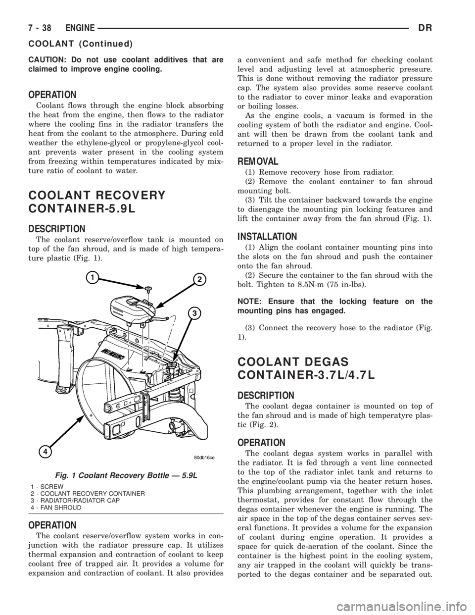
DESCRIPTION
The coolant reserve/overflow tank is mounted on
top of the fan shroud, and is made of high tempera-
ture plastic (Fig. 1).
OPERATION
The coolant reserve/overflow system works in con-
junction with the radiator pressure cap. It utilizes
thermal expansion and contraction of coolant to keep
coolant free of trapped air. It provides a volume for
expansion and contraction of coolant. It also providesa convenient and safe method for checking coolant
level and adjusting level at atmospheric pressure.
This is done without removing the radiator pressure
cap. The system also provides some reserve coolant
to the radiator to cover minor leaks and evaporation
or boiling losses.
As the engine cools, a vacuum is formed in the
cooling system of both the radiator and engine. Cool-
ant will then be drawn from the coolant tank and
returned to a proper level in the radiator.
REMOVAL
(1) Remove recovery hose from radiator.
(2) Remove the coolant container to fan shroud
mounting bolt.
(3) Tilt the container backward towards the engine
to disengage the mounting pin locking features and
lift the container away from the fan shroud (Fig. 1).
INSTALLATION
(1) Align the coolant container mounting pins into
the slots on the fan shroud and push the container
onto the fan shroud.
(2) Secure the container to the fan shroud with the
bolt. Tighten to 8.5N´m (75 in-lbs).
NOTE: Ensure that the locking feature on the
mounting pins has engaged.
(3) Connect the recovery hose to the radiator (Fig.
1).
COOLANT DEGAS
CONTAINER-3.7L/4.7L
DESCRIPTION
The coolant degas container is mounted on top of
the fan shroud and is made of high temperatyre plas-
tic (Fig. 2).
OPERATION
The coolant degas system works in parallel with
the radiator. It is fed through a vent line connected
to the top of the radiator inlet tank and returns to
the engine/coolant pump via the heater return hoses.
This plumbing arrangement, together with the inlet
thermostat, provides for constant flow through the
degas container whenever the engine is running. The
air space in the top of the degas container serves sev-
eral functions. It provides a volume for the expansion
of coolant during engine operation. It provides a
space for quick de-aeration of the coolant. Since the
container is the highest point in the cooling system,
any air trapped in the coolant will quickly be trans-
ported to the degas container and be separated out.
Fig. 1 Coolant Recovery Bottle Ð 5.9L
1 - SCREW
2 - COOLANT RECOVERY CONTAINER
3 - RADIATOR/RADIATOR CAP
4 - FAN SHROUD
7 - 38 ENGINEDR
COOLANT (Continued)
Page 485 of 2895

COLD FOULING/CARBON FOULING
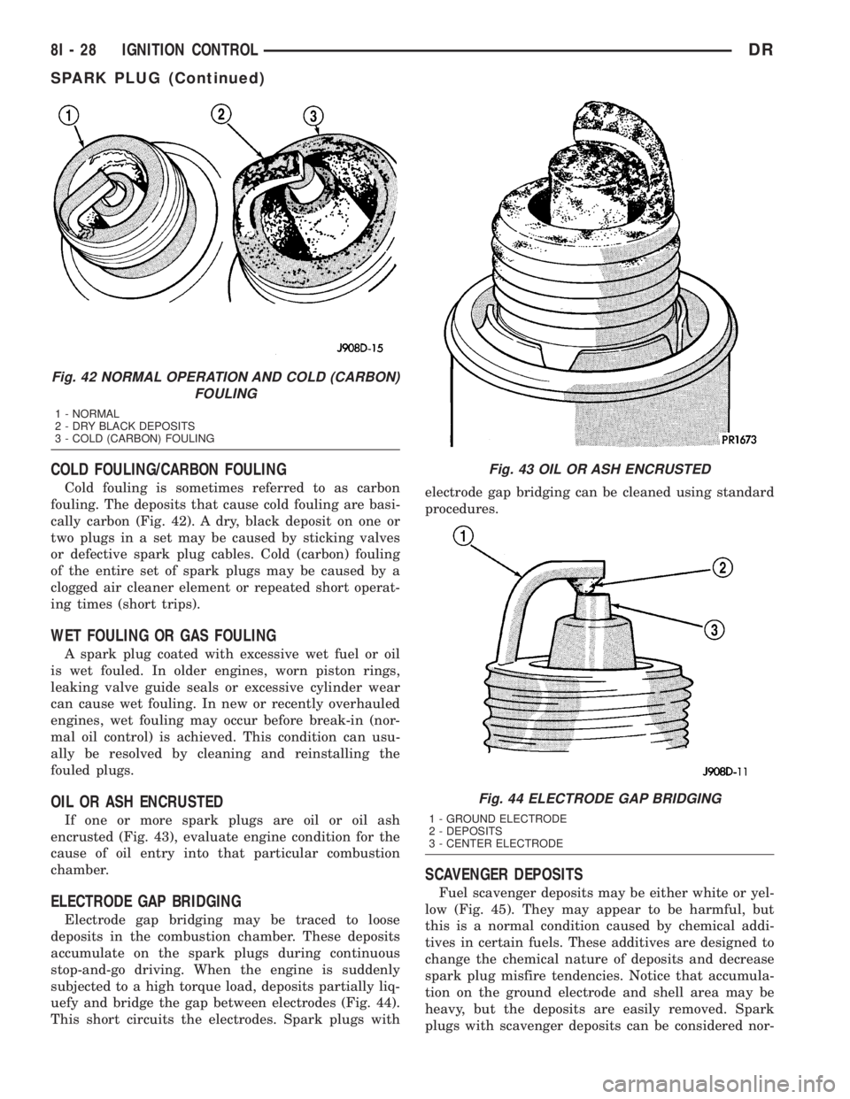
Cold fouling is sometimes referred to as carbon
fouling. The deposits that cause cold fouling are basi-
cally carbon (Fig. 42). A dry, black deposit on one or
two plugs in a set may be caused by sticking valves
or defective spark plug cables. Cold (carbon) fouling
of the entire set of spark plugs may be caused by a
clogged air cleaner element or repeated short operat-
ing times (short trips).
WET FOULING OR GAS FOULING
A spark plug coated with excessive wet fuel or oil
is wet fouled. In older engines, worn piston rings,
leaking valve guide seals or excessive cylinder wear
can cause wet fouling. In new or recently overhauled
engines, wet fouling may occur before break-in (nor-
mal oil control) is achieved. This condition can usu-
ally be resolved by cleaning and reinstalling the
fouled plugs.
OIL OR ASH ENCRUSTED
If one or more spark plugs are oil or oil ash
encrusted (Fig. 43), evaluate engine condition for the
cause of oil entry into that particular combustion
chamber.
ELECTRODE GAP BRIDGING
Electrode gap bridging may be traced to loose
deposits in the combustion chamber. These deposits
accumulate on the spark plugs during continuous
stop-and-go driving. When the engine is suddenly
subjected to a high torque load, deposits partially liq-
uefy and bridge the gap between electrodes (Fig. 44).
This short circuits the electrodes. Spark plugs withelectrode gap bridging can be cleaned using standard
procedures.
SCAVENGER DEPOSITS
Fuel scavenger deposits may be either white or yel-
low (Fig. 45). They may appear to be harmful, but
this is a normal condition caused by chemical addi-
tives in certain fuels. These additives are designed to
change the chemical nature of deposits and decrease
spark plug misfire tendencies. Notice that accumula-
tion on the ground electrode and shell area may be
heavy, but the deposits are easily removed. Spark
plugs with scavenger deposits can be considered nor-
Fig. 42 NORMAL OPERATION AND COLD (CARBON)
FOULING
1 - NORMAL
2 - DRY BLACK DEPOSITS
3 - COLD (CARBON) FOULING
Fig. 43 OIL OR ASH ENCRUSTED
Fig. 44 ELECTRODE GAP BRIDGING
1 - GROUND ELECTRODE
2 - DEPOSITS
3 - CENTER ELECTRODE
8I - 28 IGNITION CONTROLDR
SPARK PLUG (Continued)