2003 DODGE RAM ECO mode
[x] Cancel search: ECO modePage 5 of 2895

BODY CODE PLATE
DESCRIPTION
The Body Code Plate (Fig. 5) is located on the right
front hydroform fender rail just behind the headlight
assembly (Fig. 4). There are seven lines of informa-
tion on the body code plate. Lines 5, 6, and 7 are not
used to define service information. Information reads
from left to right, starting with line 4 in the center of
the plate to line 1 at the bottom of the plate.
The last code imprinted on a vehicle code plate will
be followed by the imprinted word END. When two
vehicle code plates are required, the last available
spaces on the first plate will be imprinted with the
letters CTD (for continued).
When a second vehicle code plate is necessary, the
first four spaces on each row will not be used because
of the plate overlap.
BODY CODE PLATEÐLINE 4
DIGITS 1 THROUGH 12
Vehicle Order Number
DIGITS 13, 14, AND 15
Transmission Codes
²DGT = 4±speed Automatic (46RE)
²DG4 = 4±speed Automatic (45RFE)
²DGP = 4±speed Automatic (47RE)
²DG8 = 4±speed Automatic (48RE)
²DDC = 5±speed Manual (NV3500)
²DDP = 5±speed Manual (NV4500)
²DEE = 6±speed Manual (NV5600)
DIGITS 16, 17, AND 18
Car Line Shell
²DR1=15004X2
²DR6=15004X4
²DR2=25004X2
²DR7=25004X4
²DR3=35004X2
²DR8=35004X4
Fig. 4 BODY CODE PLATE LOCATION
1 - FENDER
2 - RADIATOR CROSSMEMBER
3 - HYDROFORM FENDER RAIL
4 - RIVOT (2)
5 - BODY CODE PLATE
Fig. 5 BODY CODE PLATE
1 - PRIMARY PAINT
2 - SECONDARY PAINT
3 - TRANSMISSION CODE
4 - VEHICLE MODEL NUMBER
5 - ENGINE CODE
6 - INTERIOR TRIM CODE
7 - VEHICLE IDENTIFICATION NUMBER
8 - TAILGATE CODE
9 - CARGO BOX CODE
10 - TAILGATE TRIM CODE
11 - BODY-IN-WHITE SEQUENCE
12 - MARKET CODE
13 - SPECIES CODE
14 - PAINT PROCEDURE
15 - VEHICLE ORDER NUMBER
4 INTRODUCTIONDR
Page 23 of 2895

Miles 105,000 108,000 111,000 114,000 117,000 120,000
(Kilometers) (168 000) (173 000) (178 000) (182 000) (187 000) (192 000)
Change engine oil and engine
oil filter.XXXXX X
Lubricate outer tie rod ends
2500/3500 (4X4) models only.XXX
Drain and refill transfer case
fluid.X
Change rear axle fluid. X X
Change front axle fluid (4X4). X X
Inspect brake linings. X X
Inspect engine air cleaner
filter, replace if necessary.XX
Replace spark plugs.X
Replace ignition cables
(5.7L/5.9L/8.0L).X
Inspect PCV valve, replace
as necessary.X*
Inspect auto tension drive belt
and replace if required
(3.7L/4.7L/5.7L/5.9L/8.0L).X³ X³
Drain and refill automatic
tranmission fluid, change filter
and adjust bands (46RE/
47RE/48RE).X
Drain and refill automatic
tranmission fluid and change
main sump filter (45RFE/
545RFE only).X
* This maintenance is recommended by the manu-
facture to the owner but is not required to maintain
the emissions warranty.
³ This maintenance is not required if previously
replaced.
Inspection and service should also be performed
anytime a malfunction is observed or suspected.
Retain all receipts.
0 - 10 LUBRICATION & MAINTENANCEDR
MAINTENANCE SCHEDULES (Continued)
Page 25 of 2895
![DODGE RAM 2003 Service Repair Manual Miles 72,000 78,000 84,000 90,000 96,000 100,000
(Kilometers) (115 000) (125 000) (134 000) (144 000) (154 000) (160 000)
[Months] [72] [78] [84] [90] [96]
Change engine oil and engine oil filter.XXXX DODGE RAM 2003 Service Repair Manual Miles 72,000 78,000 84,000 90,000 96,000 100,000
(Kilometers) (115 000) (125 000) (134 000) (144 000) (154 000) (160 000)
[Months] [72] [78] [84] [90] [96]
Change engine oil and engine oil filter.XXXX](/manual-img/12/56913/w960_56913-24.png)
Miles 72,000 78,000 84,000 90,000 96,000 100,000
(Kilometers) (115 000) (125 000) (134 000) (144 000) (154 000) (160 000)
[Months] [72] [78] [84] [90] [96]
Change engine oil and engine oil filter.XXXXX
Lubricate outer tie rod ends 2500/3500
(4X4) models only.XXXXX
Drain and refill transfer case fluid. X
Flush and replace engine coolant, if not
done at 60 mos.X
Flush and replace Power Steering Fluid.X
Inspect brake linings. X X
Replace engine air cleaner filter.X
Replace spark plugs.X
Replace ignition cables (5.7L/5.9L/
8.0L).X
Inspect PCV valve, replace as
necessary.X*
Inspect auto tension drive belt and
replace if required (3.7L/4.7L/5.7L/5.9L/
8.0L).X
Drain and refill automatic tranmission
fluid, change filter and adjust bands
(46RE/47RE/48RE).X
Drain and refill automatic tranmission
fluid and change main sump filter and
spin-on cooler return filter (if equipped)
[45RFE/545RFE only].X
Miles 102,000 108,000 114,000 120,000
(Kilometers) (163 000) (173 000) (182 000) (192 000)
[Months] [102] [108] [114] [120]
Change engine oil and engine oil filter. X X X X
Check transfer case fluid level.X
Lubricate outer tie rod ends 2500/3500 (4X4) models only. X X X X
Inspect brake linings. X
Inspect auto tension drive belt and replace if required
(3.7L/4.7L/5.7L/5.9L/8.0L).X³X³
Replace engine air cleaner filter.X
Replace spark plugs.X
* This maintenance is recommended by the manu-
facture to the owner but is not required to maintain
the emissions warranty.
³ This maintenance is not required if previously
replaced.
Inspection and service should also be performed
anytime a malfunction is observed or suspected.
Retain all receipts.WARNING: You can be badly injured working on or
around a motor vehicle. Do only that service work
for which you have the knowledge and the right
equipment. If you have any doubt about your ability
to perform a service job, take your vehicle to a
competent mechanic.
0 - 12 LUBRICATION & MAINTENANCEDR
MAINTENANCE SCHEDULES (Continued)
Page 246 of 2895

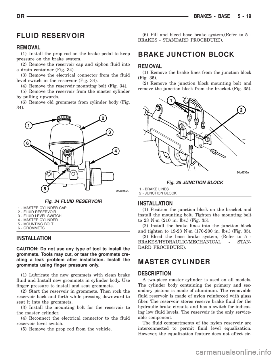
FLUID RESERVOIR
REMOVAL
(1) Install the prop rod on the brake pedal to keep
pressure on the brake system.
(2) Remove the reservoir cap and siphon fluid into
a drain container (Fig. 34).
(3) Remove the electrical connector from the fluid
level switch in the reservoir (Fig. 34).
(4) Remove the reservoir mounting bolt (Fig. 34).
(5) Remove the reservoir from the master cylinder
by pulling upwards.
(6) Remove old grommets from cylinder body (Fig.
34).
INSTALLATION
CAUTION: Do not use any type of tool to install the
grommets. Tools may cut, or tear the grommets cre-
ating a leak problem after installation. Install the
grommets using finger pressure only.
(1) Lubricate the new grommets with clean brake
fluid and Install new grommets in cylinder body. Use
finger pressure to install and seat grommets.
(2) Start the reservoir in grommets. Then rock the
reservoir back and forth while pressing downward to
seat it into the grommets.
(3) Install the mounting bolt for the reservoir to
the master cylinder.
(4) Reconnect the electrical connector to the fluid
reservoir level switch.
(5) Remove the prop rod from the vehicle.(6) Fill and bleed base brake system,(Refer to 5 -
BRAKES - STANDARD PROCEDURE).
BRAKE JUNCTION BLOCK
REMOVAL
(1) Remove the brake lines from the junction block
(Fig. 35).
(2) Remove the junction block mounting bolt and
remove the junction block from the bracket (Fig. 35).
INSTALLATION
(1) Position the junction block on the bracket and
install the mounting bolt. Tighten the mounting bolt
to 23 N´m (210 in. lbs.) (Fig. 35).
(2) Install the brake lines into the junction block
and tighten to 19-23 N´m (170-200 in. lbs.) (Fig. 35).
(3) Bleed the base brake system, (Refer to 5 -
BRAKES/HYDRAULIC/MECHANICAL - STAN-
DARD PROCEDURE).
MASTER CYLINDER
DESCRIPTION
A two-piece master cylinder is used on all models.
The cylinder body containing the primary and sec-
ondary pistons is made of aluminum. The removable
fluid reservoir is made of nylon reinforced with glass
fiber. The reservoir stores reserve brake fluid for the
hydraulic brake circuits and has a switch for indicat-
ing low fluid levels. The reservoir is the only service-
able component.
The fluid compartments of the nylon reservoir are
interconnected to permit fluid level equalization.
However, the equalization feature does not affect cir-
Fig. 34 FLUID RESERVOIR
1 - MASTER CYLINDER CAP
2 - FLUID RESERVOIR
3 - FLUID LEVEL SWITCH
4 - MASTER CYLINDER
5 - MOUNTING BOLT
6 - GROMMETS
Fig. 35 JUNCTION BLOCK
1 - BRAKE LINES
2 - JUNCTION BLOCK
DRBRAKES - BASE 5 - 19
Page 252 of 2895

(2) Install the one mounting bolt for the adjustable
pedal motor (Fig. 46).
(3) Clip the cable fasteners to the support.
(4) Reconnect the electrical connector.
(5) Reconnect the adjustable pedal cables to the
brake and accelerator pedals.
(6) Install the new brake light switch (Refer to 8 -
ELECTRICAL/LAMPS/LIGHTING - EXTERIOR/
BRAKE LAMP SWITCH - REMOVAL).
(7) Install the kneeblocker (Refer to 23 - BODY/IN-
STRUMENT PANEL/STEERING COLUMN OPEN-
ING COVER - INSTALLATION).
(8) Reconnect the negative battery cable.
(9) Check for proper operation of the pedals.
POWER BRAKE BOOSTER
DESCRIPTION
All models use a tandem diaphragm, power brake
booster.
NOTE: The power brake booster is not a repairable
component. The booster must be replaced as an
assembly if diagnosis indicates a malfunction has
occurred.
OPERATION
The booster unit consists of a single housing
divided into two by a tandem diaphragm. The outer
edge of the diaphragm is secured to the housing. The
booster push rod, which connects the booster to the
brake pedal and master cylinder, is attached to the
center of the diaphragm. A check valve is used in the
booster outlet connected to the engine intake mani-
fold. Power assist is generated by utilizing a combi-
nation of vacuum and atmospheric pressure to boost
brake assist.
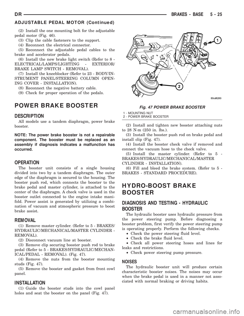
REMOVAL
(1) Remove master cylinder. (Refer to 5 - BRAKES/
HYDRAULIC/MECHANICAL/MASTER CYLINDER -
REMOVAL).
(2) Disconnect vacuum line at booster.
(3) Remove clip securing booster push rod to brake
pedal (Refer to 5 - BRAKES/HYDRAULIC/MECHAN-
ICAL/PEDAL - REMOVAL). (Fig. 47).
(4) Remove the nuts from the booster mounting
studs (Fig. 47).
(5) Remove the booster and gasket from front cowl
panel.
INSTALLATION
(1) Guide the booster studs into the cowl panel
holes and seat the booster on the panel (Fig. 47).(2) Install and tighten new booster attaching nuts
to 28 N´m (250 in. lbs.).
(3) Install the booster push rod on brake pedal and
install clip (Fig. 47).
(4) Install the booster check valve if removed and
connect the vacuum hose to the check valve.
(5) Install the master cylinder. (Refer to 5 -
BRAKES/HYDRAULIC/MECHANICAL/MASTER
CYLINDER - INSTALLATION).
(6) Fill and bleed the brake system. (Refer to 5 -
BRAKES - STANDARD PROCEDURE).
HYDRO-BOOST BRAKE
BOOSTER
DIAGNOSIS AND TESTING - HYDRAULIC
BOOSTER
The hydraulic booster uses hydraulic pressure from
the power steering pump. Before diagnosing a
booster problem, first verify the power steering pump
is operating properly. Perform the following checks.
²Check the power steering fluid level.
²Check the brake fluid level.
²Check all power steering hoses and lines for
leaks and restrictions.
²Check power steering pump pressure.
NOISES
The hydraulic booster unit will produce certain
characteristic booster noises. The noises may occur
when the brake pedal is used in a manner not asso-
ciated with normal braking or driving habits.
Fig. 47 POWER BRAKE BOOSTER
1 - MOUNTING NUT
2 - POWER BRAKE BOOSTER
DRBRAKES - BASE 5 - 25
ADJUSTABLE PEDAL MOTOR (Continued)
Page 261 of 2895

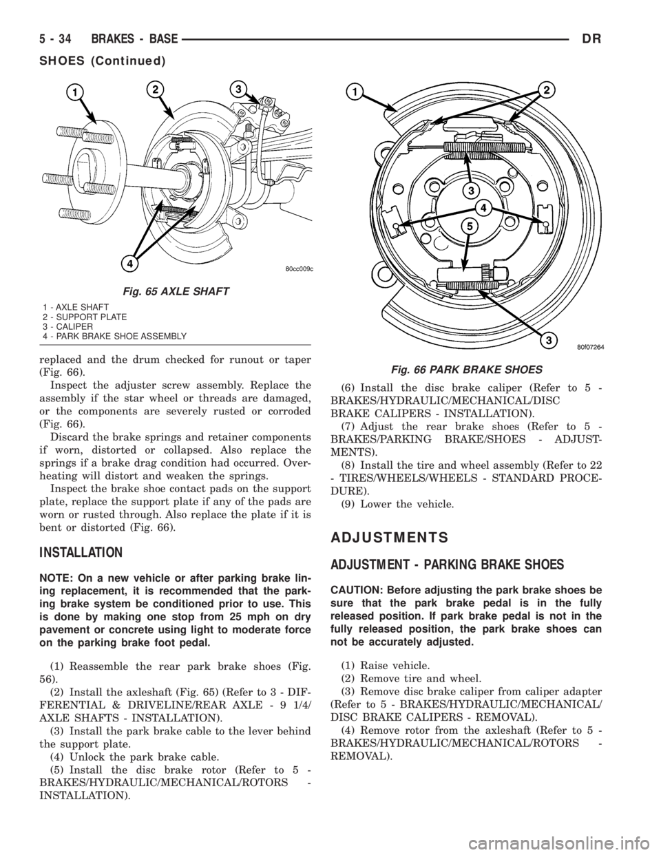
replaced and the drum checked for runout or taper
(Fig. 66).
Inspect the adjuster screw assembly. Replace the
assembly if the star wheel or threads are damaged,
or the components are severely rusted or corroded
(Fig. 66).
Discard the brake springs and retainer components
if worn, distorted or collapsed. Also replace the
springs if a brake drag condition had occurred. Over-
heating will distort and weaken the springs.
Inspect the brake shoe contact pads on the support
plate, replace the support plate if any of the pads are
worn or rusted through. Also replace the plate if it is
bent or distorted (Fig. 66).
INSTALLATION
NOTE: On a new vehicle or after parking brake lin-
ing replacement, it is recommended that the park-
ing brake system be conditioned prior to use. This
is done by making one stop from 25 mph on dry
pavement or concrete using light to moderate force
on the parking brake foot pedal.
(1) Reassemble the rear park brake shoes (Fig.
56).
(2) Install the axleshaft (Fig. 65) (Refer to 3 - DIF-
FERENTIAL & DRIVELINE/REAR AXLE - 9 1/4/
AXLE SHAFTS - INSTALLATION).
(3) Install the park brake cable to the lever behind
the support plate.
(4) Unlock the park brake cable.
(5) Install the disc brake rotor (Refer to 5 -
BRAKES/HYDRAULIC/MECHANICAL/ROTORS -
INSTALLATION).(6) Install the disc brake caliper (Refer to 5 -
BRAKES/HYDRAULIC/MECHANICAL/DISC
BRAKE CALIPERS - INSTALLATION).
(7) Adjust the rear brake shoes (Refer to 5 -
BRAKES/PARKING BRAKE/SHOES - ADJUST-
MENTS).
(8) Install the tire and wheel assembly (Refer to 22
- TIRES/WHEELS/WHEELS - STANDARD PROCE-
DURE).
(9) Lower the vehicle.
ADJUSTMENTS
ADJUSTMENT - PARKING BRAKE SHOES
CAUTION: Before adjusting the park brake shoes be
sure that the park brake pedal is in the fully
released position. If park brake pedal is not in the
fully released position, the park brake shoes can
not be accurately adjusted.
(1) Raise vehicle.
(2) Remove tire and wheel.
(3) Remove disc brake caliper from caliper adapter
(Refer to 5 - BRAKES/HYDRAULIC/MECHANICAL/
DISC BRAKE CALIPERS - REMOVAL).
(4) Remove rotor from the axleshaft (Refer to 5 -
BRAKES/HYDRAULIC/MECHANICAL/ROTORS -
REMOVAL).
Fig. 65 AXLE SHAFT
1 - AXLE SHAFT
2 - SUPPORT PLATE
3 - CALIPER
4 - PARK BRAKE SHOE ASSEMBLY
Fig. 66 PARK BRAKE SHOES
5 - 34 BRAKES - BASEDR
SHOES (Continued)
Page 263 of 2895

NOTE: On a new vehicle or after parking brake lin-
ing replacement, it is recommended that the park-
ing brake system be conditioned prior to use. This
is done by making one stop from 25 mph on dry
pavement or concrete using light to moderate force
on the parking brake foot pedal.
(18) Road test the vehicle to ensure proper func-
tion of the vehicle's brake system.
ADJUSTMENT - WITH ADJUSTING TOOL
Adjustment can be made with a standard brake
gauge or with adjusting tool. Adjustment is per-
formed with the complete brake assembly installed
on the backing plate.
(1) Be sure parking brake lever is fully released.
(2) Raise vehicle so rear wheels can be rotated
freely.
(3) Remove plug from each access hole in brake
support plates.
(4) Loosen parking brake cable adjustment nut
until there is slack in front cable.
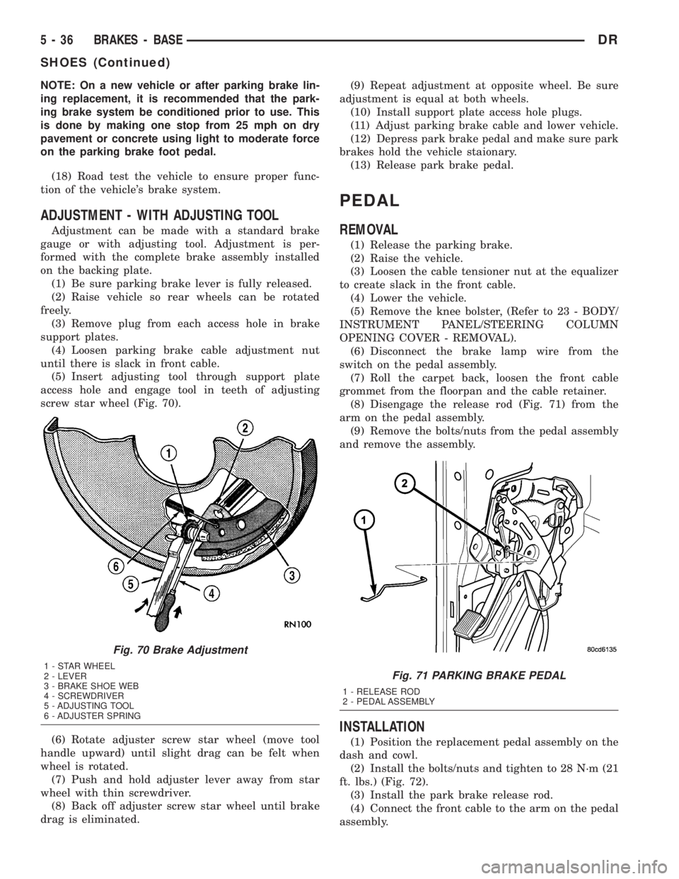
(5) Insert adjusting tool through support plate
access hole and engage tool in teeth of adjusting
screw star wheel (Fig. 70).
(6) Rotate adjuster screw star wheel (move tool
handle upward) until slight drag can be felt when
wheel is rotated.
(7) Push and hold adjuster lever away from star
wheel with thin screwdriver.
(8) Back off adjuster screw star wheel until brake
drag is eliminated.(9) Repeat adjustment at opposite wheel. Be sure
adjustment is equal at both wheels.
(10) Install support plate access hole plugs.
(11) Adjust parking brake cable and lower vehicle.
(12) Depress park brake pedal and make sure park
brakes hold the vehicle staionary.
(13) Release park brake pedal.
PEDAL
REMOVAL
(1) Release the parking brake.
(2) Raise the vehicle.
(3) Loosen the cable tensioner nut at the equalizer
to create slack in the front cable.
(4) Lower the vehicle.
(5) Remove the knee bolster, (Refer to 23 - BODY/
INSTRUMENT PANEL/STEERING COLUMN
OPENING COVER - REMOVAL).
(6) Disconnect the brake lamp wire from the
switch on the pedal assembly.
(7) Roll the carpet back, loosen the front cable
grommet from the floorpan and the cable retainer.
(8) Disengage the release rod (Fig. 71) from the
arm on the pedal assembly.
(9) Remove the bolts/nuts from the pedal assembly
and remove the assembly.
INSTALLATION
(1) Position the replacement pedal assembly on the
dash and cowl.
(2) Install the bolts/nuts and tighten to 28 N´m (21
ft. lbs.) (Fig. 72).
(3) Install the park brake release rod.
(4) Connect the front cable to the arm on the pedal
assembly.
Fig. 70 Brake Adjustment
1 - STAR WHEEL
2 - LEVER
3 - BRAKE SHOE WEB
4 - SCREWDRIVER
5 - ADJUSTING TOOL
6 - ADJUSTER SPRINGFig. 71 PARKING BRAKE PEDAL
1 - RELEASE ROD
2 - PEDAL ASSEMBLY
5 - 36 BRAKES - BASEDR
SHOES (Continued)
Page 288 of 2895

COOLING
TABLE OF CONTENTS
page page
COOLING
DESCRIPTION
DESCRIPTION - COOLING SYSTEM FLOW
3.7L/4.7L ENGINE......................1
DESCRIPTION - COOLING SYSTEM FLOW -
5.9L ENGINE..........................1
DESCRIPTIONÐCOOLING SYSTEM FLOW -
5.9L DIESEL..........................2
DESCRIPTION - HOSE CLAMPS...........3
OPERATION
OPERATIONÐCOOLING SYSTEM.........3
OPERATIONÐHOSE CLAMPS............5
DIAGNOSIS AND TESTING
DIAGNOSIS AND TESTINGÐON-BOARD
DIAGNOSTICS (OBD)...................5
DIAGNOSIS AND TESTINGÐCOOLING
SYSTEM - TESTING FOR LEAKS..........5
DIAGNOSIS AND TESTING - COOLING
SYSTEM DIESEL ENGINE................7
DIAGNOSIS AND TESTING - PRELIMINARY
CHECKS............................10
STANDARD PROCEDURE
STANDARD PROCEDURE - COOLANT
LEVEL CHECK........................17STANDARD PROCEDURE - COOLING
SYSTEM CLEANING/REVERSE FLUSHING . . 17
STANDARD PROCEDUREÐDRAINING
COOLING SYSTEM 3.7L/4.7L/5.7L ENGINE . . 18
STANDARD PROCEDURE - REFILLING
COOLING SYSTEM 3.7L/4.7L/5.7L ENGINE . . 18
STANDARD PROCEDUREÐDRAINING
COOLING SYSTEM 5.9L/8.0L ENGINE......18
STANDARD PROCEDUREÐREFILLING
COOLING SYSTEM 5.9L/8.0L ENGINE......18
STANDARD PROCEDUREÐDRAINING
COOLING SYSTEM 5.9L DIESEL ENGINE . . . 19
STANDARD PROCEDUREÐREFILLING
COOLING SYSTEM 5.9L DIESEL ENGINE . . . 19
STANDARD PROCEDURE - ADDING
ADDITIONAL COOLANT.................19
SPECIFICATIONS
TORQUE............................20
SPECIFICATIONS -....................20
SPECIAL TOOLS
COOLING...........................20
ACCESSORY DRIVE......................22
ENGINE...............................35
TRANSMISSION.........................72
COOLING
DESCRIPTION
DESCRIPTION - COOLING SYSTEM FLOW
3.7L/4.7L ENGINE
The cooling system regulates engine operating tem-
perature. It allows the engine to reach normal oper-
ating temperature as quickly as possible. It also
maintains normal operating temperature and pre-
vents overheating.
The cooling system provides a means of heating
the passenger compartment and cooling the auto-
matic transmission fluid (if equipped). The cooling
system is pressurized and uses a centrifugal water
pump to circulate coolant through the system and a
coolant deaeration and reserve system that utilizes a
pressurized degas bottle (hot bottle).
An optional factory installed maximum duty cool-
ing package is available on most models. This pack-
age will provide additional cooling capacity forvehicles used under extreme conditions such as
trailer towing in high ambient temperatures (Fig. 1).
DESCRIPTION - COOLING SYSTEM FLOW -
5.9L ENGINE
The cooling system regulates engine operating tem-
perature. It allows the engine to reach normal oper-
ating temperature as quickly as possible. It also
maintains normal operating temperature and pre-
vents overheating.
The cooling system also provides a means of heat-
ing the passenger compartment and cooling the auto-
matic transmission fluid (if equipped). The cooling
system uses a coolant recovery / reserve system that
utilizes an ambient overflow bottle.
An optional factory installed maximum duty cool-
ing package is available on most models. This pack-
age will provide additional cooling capacity for
vehicles used under extreme conditions such as
trailer towing in high ambient temperatures (Fig. 2).
DRCOOLING 7 - 1