2003 DODGE RAM change wheel
[x] Cancel search: change wheelPage 16 of 2895

SPECIALIZED LUBRICANTS AND OILS
Some maintenance or repair procedures may
require the use of specialized lubricants or oils. Con-
sult the appropriate sections in this manual for the
correct application of these lubricants.
DESCRIPTION - POWER STEERING FLUID
MopartATF +4, Automatic Transmission Fluid is
required in the power steering system. Substitute
fluids can induce power steering system failure.
MopartATF +4, Automatic Transmission Fluid
when new is red in color. The ATF is dyed red so it
can be identified from other fluids used in the vehicle
such as engine oil or antifreeze. The red color is not
permanent and is not an indicator of fluid condition.
As the vehicle is driven, the ATF will begin to look
darker in color and may eventually become brown.
This is normal.ATF+4 also has a unique odor that
may change with age. Consequently, odor and color
cannot be used to indicate the fluid condition or the
need for a fluid change.
DESCRIPTION - ENGINE COOLANT
WARNING: ANTIFREEZE IS AN ETHYLENE GLYCOL
BASE COOLANT AND IS HARMFUL IF SWAL-
LOWED OR INHALED. IF SWALLOWED, DRINK
TWO GLASSES OF WATER AND INDUCE VOMIT-
ING. IF INHALED, MOVE TO FRESH AIR AREA.
SEEK MEDICAL ATTENTION IMMEDIATELY. DO NOT
STORE IN OPEN OR UNMARKED CONTAINERS.
WASH SKIN AND CLOTHING THOROUGHLY AFTER
COMING IN CONTACT WITH ETHYLENE GLYCOL.
KEEP OUT OF REACH OF CHILDREN. DISPOSE OF
GLYCOL BASE COOLANT PROPERLY, CONTACT
YOUR DEALER OR GOVERNMENT AGENCY FOR
LOCATION OF COLLECTION CENTER IN YOUR
AREA. DO NOT OPEN A COOLING SYSTEM WHEN
THE ENGINE IS AT OPERATING TEMPERATURE OR
HOT UNDER PRESSURE, PERSONAL INJURY CAN
RESULT. AVOID RADIATOR COOLING FAN WHENENGINE COMPARTMENT RELATED SERVICE IS
PERFORMED, PERSONAL INJURY CAN RESULT.
CAUTION: Use of Propylene Glycol based coolants
is not recommended, as they provide less freeze
protection and less corrosion protection.
The cooling system is designed around the coolant.
The coolant must accept heat from engine metal, in
the cylinder head area near the exhaust valves and
engine block. Then coolant carries the heat to the
radiator where the tube/fin radiator can transfer the
heat to the air.
The use of aluminum cylinder blocks, cylinder
heads, and water pumps requires special corrosion
protection. MopartAntifreeze/Coolant, 5
Year/100,000 Mile Formula (MS-9769), or the equiva-
lent ethylene glycol base coolant with organic corro-
sion inhibitors (called HOAT, for Hybrid Organic
Additive Technology) is recommended. This coolant
offers the best engine cooling without corrosion when
mixed with 50% Ethylene Glycol and 50% distilled
water to obtain a freeze point of -37ÉC (-35ÉF). If it
loses color or becomes contaminated, drain, flush,
and replace with fresh properly mixed coolant solu-
tion.
CAUTION: MoparTAntifreeze/Coolant, 5
Year/100,000 Mile Formula (MS-9769) may not be
mixed with any other type of antifreeze. Mixing of
coolants other than specified (non-HOAT or other
HOAT), may result in engine damage that may not
be covered under the new vehicle warranty, and
decreased corrosion protection.
COOLANT PERFORMANCE
The required ethylene-glycol (antifreeze) and water
mixture depends upon climate and vehicle operating
conditions. The coolant performance of various mix-
tures follows:
Pure Water-Water can absorb more heat than a
mixture of water and ethylene-glycol. This is for pur-
pose of heat transfer only. Water also freezes at a
higher temperature and allows corrosion.
100 percent Ethylene-Glycol-The corrosion
inhibiting additives in ethylene-glycol need the pres-
ence of water to dissolve. Without water, additives
form deposits in system. These act as insulation
causing temperature to rise to as high as 149ÉC
(300ÉF). This temperature is hot enough to melt plas-
tic and soften solder. The increased temperature can
result in engine detonation. In addition, 100 percent
ethylene-glycol freezes at -22ÉC (-8ÉF).
50/50 Ethylene-Glycol and Water-Is the recom-
mended mixture, it provides protection against freez-
ing to -37ÉC (-34ÉF). The antifreeze concentration
Fig. 4 NLGI SYMBOL
1 - WHEEL BEARINGS
2 - CHASSIS LUBRICATION
3 - CHASSIS AND WHEEL BEARINGS
DRLUBRICATION & MAINTENANCE 0 - 3
FLUID TYPES (Continued)
Page 33 of 2895
To adjust the vehicle height turn the torsion bar
adjustment bolt CLOCKWISE to raise the vehicle
and COUNTER CLOCKWISE to lower the vehicle.
CAUTION: ALWAYS raise the vehicle to the correct
suspension height, NEVER lower the vehicle to
obtain the correct suspension height. If the vehicle
suspension height is too high, lower the vehicle
below the height specification. Then raise the vehi-
cle to the correct suspension height specification.
This will insure the vehicle maintains the proper
suspension height.
NOTE: If a height adjustment has been made, per-
form height measurement again on both sides of
the vehicle.
STANDARD PROCEDURE - CAMBER AND
CASTER ADJUSTMENT
NOTE: 4X4 (LD) SUSPENSION HEIGHT MEASURE-
MENT MUST BE PERFORMED BEFORE AN ALIGN-
MENT.
NOTE: When the upper control arm pivot bolts are
loosened the upper control arm will normally go
inwards toward the frame automatically with the
weight of the vehicle.
Camber and caster angle adjustments involve
changing the position of the upper control arm incon-
junction with the slotted holes in the frame brackets,
Install special tool 8876 between the top of the upper
control arm bracket and the upper control arm (on
1500 series 4X2 & 4X4). Install special tool 8876
between the bottom of the upper control arm bracket
pressing the tool against the frame and the upper
control arm (on 2500/3500 series 4X2) in order to
move the upper control arm outwards for proper
adjustment with the vehicle at normal ride height
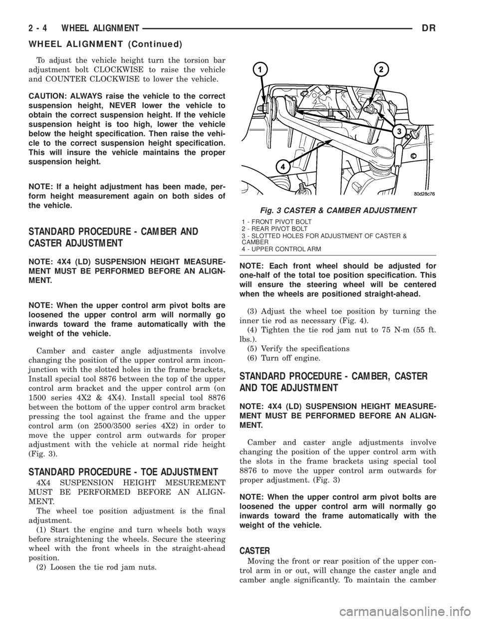
(Fig. 3).
STANDARD PROCEDURE - TOE ADJUSTMENT
4X4 SUSPENSION HEIGHT MESUREMENT
MUST BE PERFORMED BEFORE AN ALIGN-
MENT.
The wheel toe position adjustment is the final
adjustment.
(1) Start the engine and turn wheels both ways
before straightening the wheels. Secure the steering
wheel with the front wheels in the straight-ahead
position.
(2) Loosen the tie rod jam nuts.NOTE: Each front wheel should be adjusted for
one-half of the total toe position specification. This
will ensure the steering wheel will be centered
when the wheels are positioned straight-ahead.
(3) Adjust the wheel toe position by turning the
inner tie rod as necessary (Fig. 4).
(4) Tighten the tie rod jam nut to 75 N´m (55 ft.
lbs.).
(5) Verify the specifications
(6) Turn off engine.
STANDARD PROCEDURE - CAMBER, CASTER
AND TOE ADJUSTMENT
NOTE: 4X4 (LD) SUSPENSION HEIGHT MEASURE-
MENT MUST BE PERFORMED BEFORE AN ALIGN-
MENT.
Camber and caster angle adjustments involve
changing the position of the upper control arm with
the slots in the frame brackets using special tool
8876 to move the upper control arm outwards for
proper adjustment. (Fig. 3)
NOTE: When the upper control arm pivot bolts are
loosened the upper control arm will normally go
inwards toward the frame automatically with the
weight of the vehicle.
CASTER
Moving the front or rear position of the upper con-
trol arm in or out, will change the caster angle and
camber angle significantly. To maintain the camber
Fig. 3 CASTER & CAMBER ADJUSTMENT
1 - FRONT PIVOT BOLT
2 - REAR PIVOT BOLT
3 - SLOTTED HOLES FOR ADJUSTMENT OF CASTER &
CAMBER
4 - UPPER CONTROL ARM
2 - 4 WHEEL ALIGNMENTDR
WHEEL ALIGNMENT (Continued)
Page 34 of 2895

angle while adjusting caster, move one pivot bolt of
the upper control arm in or out. Then move the other
pivot bolt of the upper control arm in the opposite
direction. Install special tool 8876 between the top of
the upper control arm bracket and the upper control
arm (on 1500 series 4X2 & 4X4). Install special tool
8876 between the bottom of the upper control arm
bracket pressing the tool against the frame and the
upper control arm (on 2500/3500 series 4X2) in order
to move the upper control arm outwards for proper
adjustment with the vehicle at normal ride height
(Fig. 3).
To increase positive caster angle, move the rear
position of the upper control arm inward (toward the
engine). Move the front of the upper control arm out-
ward (away from the engine) slightly until the origi-
nal camber angle is obtained using special tool 8876
to move the upper control arm for proper adjustment.
(Fig. 3)
CAMBER
Move both pivot bolts of the upper control arm
together in or out. This will change the camber angle
significantly and little effect on the caster angle
using special tool 8876 to move the upper control
arm for proper adjustment. (Fig. 3)
After adjustment is made tighten the upper control
arm nuts to proper torque specification.
TOE ADJUSTMENT
The wheel toe position adjustment is the final
adjustment.
(1) Start the engine and turn wheels both ways
before straightening the wheels. Secure the steering
wheel with the front wheels in the straight-ahead
position.
(2) Loosen the tie rod jam nuts.
NOTE: Each front wheel should be adjusted for
one-half of the total toe position specification. This
will ensure the steering wheel will be centered
when the wheels are positioned straight-ahead.
(3) Adjust the wheel toe position by turning the
inner tie rod as necessary (Fig. 4).
(4) Tighten the tie rod jam nut to 75 N´m (55 ft.
lbs.).
(5) Verify the specifications
(6) Turn off engine.
STANDARD PROCEDURE - ALIGNMENT
LINK/COIL SUSPENSION
Before each alignment reading the vehicle should
be jounced (rear first, then front). Grasp each
bumper at the center and jounce the vehicle up and
down several times. Always release the bumper inthe down position.Set the front end alignment to
specifications while the vehicle is in its NOR-
MALLY LOADED CONDITION.
CAMBER:The wheel camber angle is preset and
is not adjustable.
CASTER:Check the caster of the front axle for
correct angle. Be sure the axle is not bent or twisted.
Road test the vehicle and make left and right turn.
Observe the steering wheel return-to-center position.
Low caster will cause poor steering wheel returnabil-
ity.
Caster can be adjusted by rotating the cams on the
lower suspension arm (Fig. 5).
TOE POSITION:The wheel toe position adjust-
ment should be the final adjustment.
Fig. 4 TIE ROD END
1 - JAM NUT
2 - TIE ROD - INNER
3 - TIE ROD END - OUTER
Fig. 5 ALIGNMENT ADJUSTMENT CAM
1 - BRACKET REINFORCEMENT
2 - ADJUSTING BOLT
3 - ADJUSTMENT CAM
DRWHEEL ALIGNMENT 2 - 5
WHEEL ALIGNMENT (Continued)
Page 35 of 2895
(1) Start the engine and turn wheels both ways
before straightening the wheels. Center and Secure
the steering wheel and turn off engine.
(2) Loosen the adjustment sleeve clamp bolts.
(3) Adjust the right wheel toe position with the
drag link. Turn the sleeve until the right wheel is at
the correct TOE-IN position. Position clamp bolts to
their original position and tighten to specifications.
Make sure the toe setting does not change dur-
ing clamp tightening.
(4) Adjust left wheel toe position with tie rod at
left knuckle. Turn the sleeve until the left wheel is at
the correct TOE-IN position. Position clamp bolts to
their original position and tighten to specifications.
Make sure the toe setting does not change dur-
ing clamp tightening.
(5) Verify the right toe setting and a straight steer-
ing wheel.
(6) Road test the vehicle.
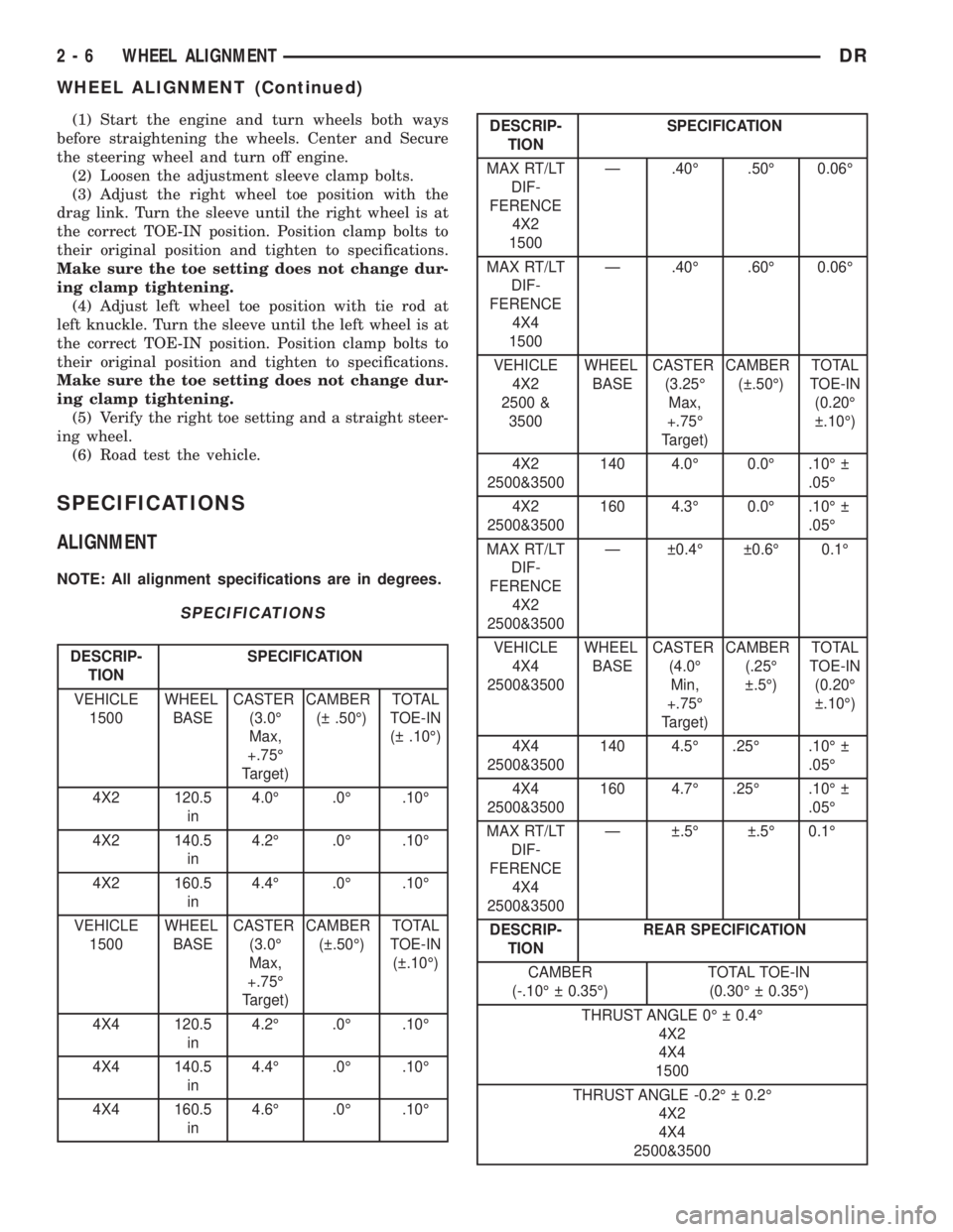
SPECIFICATIONS
ALIGNMENT
NOTE: All alignment specifications are in degrees.
SPECIFICATIONS
DESCRIP-
TIONSPECIFICATION
VEHICLE
1500WHEEL
BASECASTER
(3.0É
Max,
+.75É
Target)CAMBER
( .50É)TOTAL
TOE-IN
( .10É)
4X2 120.5
in4.0É .0É .10É
4X2 140.5
in4.2É .0É .10É
4X2 160.5
in4.4É .0É .10É
VEHICLE
1500WHEEL
BASECASTER
(3.0É
Max,
+.75É
Target)CAMBER
( .50É)TOTAL
TOE-IN
( .10É)
4X4 120.5
in4.2É .0É .10É
4X4 140.5
in4.4É .0É .10É
4X4 160.5
in4.6É .0É .10É
DESCRIP-
TIONSPECIFICATION
MAX RT/LT
DIF-
FERENCE
4X2
1500Ð .40É .50É 0.06É
MAX RT/LT
DIF-
FERENCE
4X4
1500Ð .40É .60É 0.06É
VEHICLE
4X2
2500 &
3500WHEEL
BASECASTER
(3.25É
Max,
+.75É
Target)CAMBER
( .50É)TOTAL
TOE-IN
(0.20É
.10É)
4X2
2500&3500140 4.0É 0.0É .10É
.05É
4X2
2500&3500160 4.3É 0.0É .10É
.05É
MAX RT/LT
DIF-
FERENCE
4X2
2500&3500Ð 0.4É 0.6É 0.1É
VEHICLE
4X4
2500&3500WHEEL
BASECASTER
(4.0É
Min,
+.75É
Target)CAMBER
(.25É
.5É)TOTAL
TOE-IN
(0.20É
.10É)
4X4
2500&3500140 4.5É .25É .10É
.05É
4X4
2500&3500160 4.7É .25É .10É
.05É
MAX RT/LT
DIF-
FERENCE
4X4
2500&3500Ð .5É .5É 0.1É
DESCRIP-
TIONREAR SPECIFICATION
CAMBER
(-.10É 0.35É)TOTAL TOE-IN
(0.30É 0.35É)
THRUST ANGLE 0É 0.4É
4X2
4X4
1500
THRUST ANGLE -0.2É 0.2É
4X2
4X4
2500&3500
2 - 6 WHEEL ALIGNMENTDR
WHEEL ALIGNMENT (Continued)
Page 55 of 2895

INSTALLATION
CAUTION: The left and right side torsion bars are
NOT interchangeable. The bars are identified and
stamped R or L, for right or left. The bars do not
have a front or rear end and can be installed with
either end facing forward.
(1) Insert torsion bar ends into anchor and suspen-
sion arm.
(2) Position the anchor in the frame crossmember.
(3) Install Special Tool - 8686 to the anchor and
the crossmember (Fig. 30).
(4) Increase the tension on the anchor in order to
load the torsion bar.
(5) Install the adjustment bolt and the adjuster
nut.
(6) Turn adjustment bolt clockwise the recorded
amount of turns.
(7) Remove tool - 8686 from the torsion bar cross-
member (Fig. 30).
(8) Install the transfer case skid plate (Refer to 13
- FRAME & BUMPERS/FRAME/TRANSFER CASE
SKID PLATE - INSTALLATION).
(9) Lower vehicle and adjust the front suspension
height (Refer to 2 - SUSPENSION/WHEEL ALIGN-
MENT - STANDARD PROCEDURE).
(10) Perform a wheel alignment (Refer to 2 - SUS-
PENSION/WHEEL ALIGNMENT - STANDARD
PROCEDURE).
UPPER BALL JOINT
DIAGNOSIS AND TESTING - UPPER BALL
JOINT
NOTE: If the ball joint is equipped with a lubrication
fitting, grease the joint then road test the vehicle
before performing test.
(1) Raise the front of the vehicle. Place safety floor
stands under both lower control arms as far outboard
as possible. Lower the vehicle to allow the stands to
support some or all of the vehicle weight.
(2) Remove the front tires.(3) Mount a dial indicator solidly to the frame and
then zero the dial indicator.
(4) Position dial indicator plunger on the topside of
the upper ball joint (Fig. 32).
NOTE: The dial indicator plunger must be perpen-
dicular to the machined surface of the ball joint
(Fig. 32).
NOTE: Use care not to pry or tear the ball joint
boot, when checking the free play.
(5) Position a pry bar between the steering
knuckle and the upper control arm. Pry upwards on
the upper control arm (Fig. 32).
(6) If the travel exceeds 0.5 mm (0.020 in.), replace
the upper control arm since the upper ball joint is
integral to the arm (Refer to 2 - SUSPENSION/
FRONT/UPPER CONTROL ARM - REMOVAL).
(7) If the upper ball joint is within specs reinstall
the front tires (Refer to 22 - TIRES/WHEELS/
WHEELS - STANDARD PROCEDURE).
Fig. 32 UPPER BALL JOINT PLAY
1 - DIAL INDICATOR
2 - UPPER CONTROL ARM
3-PRYBAR
4 - KNUCKLE
5 - BALL JOINT BOOT
2 - 26 FRONT - INDEPENDENT FRONT SUSPENSIONDR
TORSION BAR (Continued)
Page 70 of 2895
SPRING
DESCRIPTION
The rear suspension system uses a multi-leaf
springs and a solid drive axle. The forward end of the
springs are mounted to the body rail hangers
through rubber bushings. The rearward end of the
springs are attached to the body by the use of shack-
les. The spring and shackles use rubber bushings.
OPERATION
The springs control ride quality and maintain vehi-
cle ride height. The shackles allow the springs to
change their length as the vehicle moves over various
road conditions.
REMOVAL
(1) Raise and support the vehicle.
(2) Support the axle with a suitable holding fix-
ture.
(3) Remove the nuts, spring clamp bolts and the
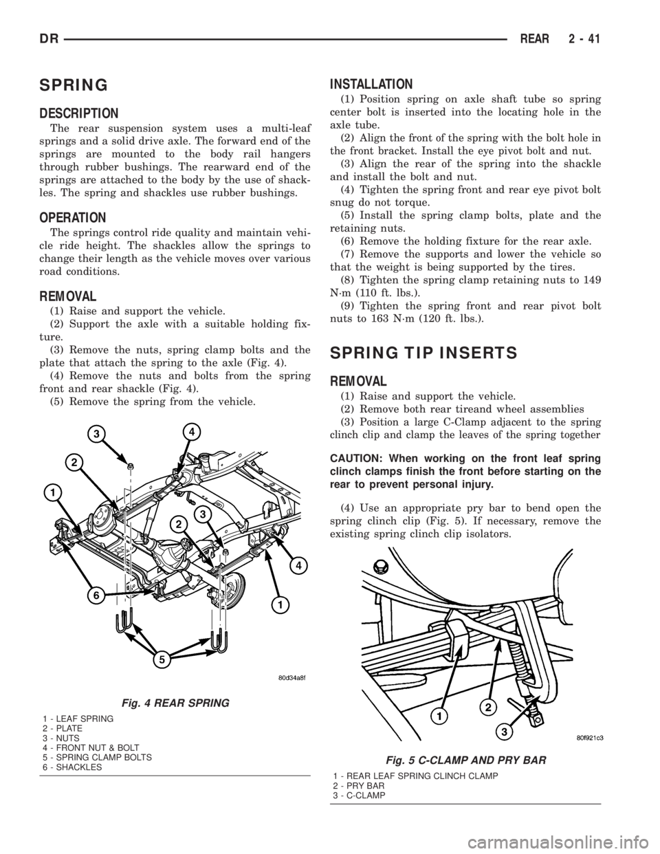
plate that attach the spring to the axle (Fig. 4).
(4) Remove the nuts and bolts from the spring
front and rear shackle (Fig. 4).
(5) Remove the spring from the vehicle.
INSTALLATION
(1) Position spring on axle shaft tube so spring
center bolt is inserted into the locating hole in the
axle tube.
(2)
Align the front of the spring with the bolt hole in
the front bracket. Install the eye pivot bolt and nut.
(3) Align the rear of the spring into the shackle
and install the bolt and nut.
(4) Tighten the spring front and rear eye pivot bolt
snug do not torque.
(5) Install the spring clamp bolts, plate and the
retaining nuts.
(6) Remove the holding fixture for the rear axle.
(7) Remove the supports and lower the vehicle so
that the weight is being supported by the tires.
(8) Tighten the spring clamp retaining nuts to 149
N´m (110 ft. lbs.).
(9) Tighten the spring front and rear pivot bolt
nuts to 163 N´m (120 ft. lbs.).
SPRING TIP INSERTS
REMOVAL
(1) Raise and support the vehicle.
(2) Remove both rear tireand wheel assemblies
(3)
Position a large C-Clamp adjacent to the spring
clinch clip and clamp the leaves of the spring together
CAUTION: When working on the front leaf spring
clinch clamps finish the front before starting on the
rear to prevent personal injury.
(4) Use an appropriate pry bar to bend open the
spring clinch clip (Fig. 5). If necessary, remove the
existing spring clinch clip isolators.
Fig. 4 REAR SPRING
1 - LEAF SPRING
2 - PLATE
3 - NUTS
4 - FRONT NUT & BOLT
5 - SPRING CLAMP BOLTS
6 - SHACKLES
Fig. 5 C-CLAMP AND PRY BAR
1 - REAR LEAF SPRING CLINCH CLAMP
2-PRYBAR
3 - C-CLAMP
DRREAR 2 - 41
Page 75 of 2895
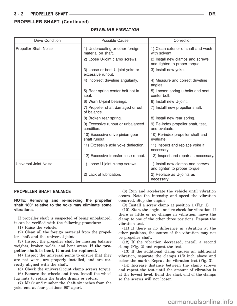
DRIVELINE VIBRATION
Drive Condition Possible Cause Correction
Propeller Shaft Noise 1) Undercoating or other foreign
material on shaft.1) Clean exterior of shaft and wash
with solvent.
2) Loose U-joint clamp screws. 2) Install new clamps and screws
and tighten to proper torque.
3) Loose or bent U-joint yoke or
excessive runout.3) Install new yoke.
4) Incorrect driveline angularity. 4) Measure and correct driveline
angles.
5) Rear spring center bolt not in
seat.5) Loosen spring u-bolts and seat
center bolt.
6) Worn U-joint bearings. 6) Install new U-joint.
7) Propeller shaft damaged or out
of balance.7) Installl new propeller shaft.
8) Broken rear spring. 8) Install new rear spring.
9) Excessive runout or unbalanced
condition.9) Re-index propeller shaft, test,
and evaluate.
10) Excessive drive pinion gear
shaft runout.10) Re-index propeller shaft and
evaluate.
11) Excessive axle yoke deflection. 11) Inspect and replace yoke if
necessary.
12) Excessive transfer case runout. 12) Inspect and repair as necessary.
Universal Joint Noise 1) Loose U-joint clamp screws. 1) Install new clamps and screws
and tighten to proper torque.
2) Lack of lubrication. 2) Replace as U-joints as
necessary.
PROPELLER SHAFT BALANCE
NOTE: Removing and re-indexing the propeller
shaft 180É relative to the yoke may eliminate some
vibrations.
If propeller shaft is suspected of being unbalanced,
it can be verified with the following procedure:
(1) Raise the vehicle.
(2) Clean all the foreign material from the propel-
ler shaft and the universal joints.
(3) Inspect the propeller shaft for missing balance
weights, broken welds, and bent areas.If the pro-
peller shaft is bent, it must be replaced.
(4) Inspect the universal joints to ensure that they
are not worn, are properly installed, and are cor-
rectly aligned with the shaft.
(5) Check the universal joint clamp screws torque.
(6) Remove the wheels and tires. Install the wheel
lug nuts to retain the brake drums or rotors.
(7) Mark and number the shaft six inches from the
yoke end at four positions 90É apart.(8) Run and accelerate the vehicle until vibration
occurs. Note the intensity and speed the vibration
occurred. Stop the engine.
(9) Install a screw clamp at position 1 (Fig. 1).
(10) Start the engine and re-check for vibration. If
there is little or no change in vibration, move the
clamp to one of the other three positions. Repeat the
vibration test.
(11) If there is no difference in vibration at the
other positions, the source of the vibration may not
be propeller shaft.
(12) If the vibration decreased, install a second
clamp (Fig. 2) and repeat the test.
(13) If the additional clamp causes an additional
vibration, separate the clamps (1/2 inch above and
below the mark). Repeat the vibration test (Fig. 3).
(14) Increase distance between the clamp screws
and repeat the test until the amount of vibration is
at the lowest level. Bend the slack end of the clamps
so the screws will not loosen.
3 - 2 PROPELLER SHAFTDR
PROPELLER SHAFT (Continued)
Page 91 of 2895
FRONT AXLE - C205F
TABLE OF CONTENTS
page page
FRONT AXLE - C205F
DESCRIPTION.........................18
OPERATION...........................18
DIAGNOSIS AND TESTING................18
REMOVAL.............................21
INSTALLATION.........................21
ADJUSTMENTS........................21
SPECIFICATIONS.......................29
SPECIAL TOOLS.......................30
AXLE SHAFTS
REMOVAL.............................33
INSTALLATION.........................33
AXLE SHAFT SEALS
REMOVAL.............................33
INSTALLATION.........................33
AXLE BEARINGS
REMOVAL.............................33INSTALLATION.........................34
PINION SEAL
REMOVAL.............................34
INSTALLATION.........................35
DIFFERENTIAL
DESCRIPTION.........................36
OPERATION...........................36
REMOVAL.............................36
DISASSEMBLY.........................37
ASSEMBLY............................38
INSTALLATION.........................38
DIFFERENTIAL CASE BEARINGS
REMOVAL.............................39
INSTALLATION.........................39
PINION GEAR/RING GEAR
REMOVAL.............................40
INSTALLATION.........................42
FRONT AXLE - C205F
DESCRIPTION
The axle consists of an alumunum center section
with an axle tube extending from one side. The tube
is pressed into the differential housing. The power is
transferred from the axle through two constant veloc-
ity (C/V) drive shafts to the wheel hubs. The drive
shafts are identical and interchangeable.
OPERATION
The axle receives power from the propeller shaft.
The propeller shaft is connected to the pinion gear
which rotates the differential through the gear mesh
with the ring gear bolted to the differential case. The
engine power is transmitted to the axle shafts
through the pinion mate and side gears. The side
gears are splined to the axle shafts.
DIAGNOSIS AND TESTING
GEAR NOISE
Axle gear noise can be caused by insufficient lubri-
cant, incorrect backlash, tooth contact, worn/damaged
gears or the carrier housing not having the proper
offset and squareness.
Gear noise usually happens at a specific speed
range. The noise can also occur during a specific type
of driving condition. These conditions are accelera-
tion, deceleration, coast, or constant load.When road testing, first warm-up the axle fluid by
driving the vehicle at least 5 miles and then acceler-
ate the vehicle to the speed range where the noise is
the greatest. Shift out-of-gear and coast through the
peak-noise range. If the noise stops or changes
greatly:
²Check for insufficient lubricant.
²Incorrect ring gear backlash.
²Gear damage.
Differential side gears and pinions can be checked
by turning the vehicle. They usually do not cause
noise during straight-ahead driving when the gears
are unloaded. The side gears are loaded during vehi-
cle turns. A worn pinion mate shaft can also cause a
snapping or a knocking noise.
BEARING NOISE
The axle shaft, differential and pinion bearings can
all produce noise when worn or damaged. Bearing
noise can be either a whining, or a growling sound.
Pinion bearings have a constant-pitch noise. This
noise changes only with vehicle speed. Pinion bearing
noise will be higher pitched because it rotates at a
faster rate. Drive the vehicle and load the differen-
tial. If bearing noise occurs, the rear pinion bearing
is the source of the noise. If the bearing noise is
heard during a coast, the front pinion bearing is the
source.
Worn or damaged differential bearings usually pro-
duce a low pitch noise. Differential bearing noise is
similar to pinion bearing noise. The pitch of differen-
3 - 18 FRONT AXLE - C205FDR