2003 DODGE RAM change wheel
[x] Cancel search: change wheelPage 2036 of 2895
Normal calibration will be performed when sump
temperature is above 50 degrees F, or in the absence
of sump temperature data, after the first 10 minutes
of vehicle operation. Calibration of the pressure
transducer offset occurs each time the output shaft
speed falls below 200 RPM. Calibration shall be
repeated each 3 seconds the output shaft speed is
below 200 RPM. A 0.5 second pulse of 95% duty cycle
is applied to the governor pressure solenoid valve
and the transducer output is read during this pulse.
Averaging of the transducer signal is necessary to
reject electrical noise.
Under cold conditions (below 50 degrees F sump),
the governor pressure solenoid valve response may
be too slow to guarantee 0 psi during the 0.5 second
calibration pulse. Calibration pulses are continued
during this period, however the transducer output
valves are discarded. Transducer offset must be read
at key-on, under conditions which promote a stable
reading. This value is retained and becomes the off-
set during the9cold9period of operation.
GOVERNOR PRESSURE SOLENOID VALVE
The inlet side of the solenoid valve is exposed to
normal transmission line pressure. The outlet side of
the valve leads to the valve body governor circuit.
The solenoid valve regulates line pressure to pro-
duce governor pressure. The average current sup-
plied to the solenoid controls governor pressure. One
amp current produces zero kPa/psi governor pres-
sure. Zero amps sets the maximum governor pres-
sure.
The powertrain control module (PCM) turns on the
trans control relay which supplies electrical power to
the solenoid valve. Operating voltage is 12 volts
(DC). The PCM controls the ground side of the sole-
noid using the governor pressure solenoid control cir-
cuit.
GOVERNOR PRESSURE SENSOR
The sensor output signal provides the necessary
feedback to the PCM. This feedback is needed to ade-
quately control governor pressure.
GOVERNOR BODY AND TRANSFER PLATE
The transfer plate channels line pressure to the
solenoid valve through the governor body. It also
channels governor pressure from the solenoid valve
to the governor circuit. It is the solenoid valve that
develops the necessary governor pressure.
GOVERNOR PRESSURE CURVES
LOW TRANSMISSION FLUID TEMPERATURE
When the transmission fluid is cold the conven-
tional governor can delay shifts, resulting in higherthan normal shift speeds and harsh shifts. The elec-
tronically controlled low temperature governor pres-
sure curve is higher than normal to make the
transmission shift at normal speeds and sooner. The
PCM uses a temperature sensor in the transmission
oil sump to determine when low temperature gover-
nor pressure is needed.
NORMAL OPERATION
Normal operation is refined through the increased
computing power of the PCM and through access to
data on engine operating conditions provided by the
PCM that were not available with the previous
stand-alone electronic module. This facilitated the
development of a load adaptive shift strategy - the
ability to alter the shift schedule in response to vehi-
cle load condition. One manifestation of this capabil-
ity is grade9hunting9prevention - the ability of the
transmission logic to delay an upshift on a grade if
the engine does not have sufficient power to main-
tain speed in the higher gear. The 3-2 downshift and
the potential for hunting between gears occurs with a
heavily loaded vehicle or on steep grades. When
hunting occurs, it is very objectionable because shifts
are frequent and accompanied by large changes in
noise and acceleration.
WIDE OPEN THROTTLE OPERATION
In wide-open throttle (WOT) mode, adaptive mem-
ory in the PCM assures that up-shifts occur at the
preprogrammed optimum speed. WOT operation is
determined from the throttle position sensor, which
is also a part of the emission control system. The ini-
tial setting for the WOT upshift is below the opti-
mum engine speed. As WOT shifts are repeated, the
PCM learns the time required to complete the shifts
by comparing the engine speed when the shifts occur
to the optimum speed. After each shift, the PCM
adjusts the shift point until the optimum speed is
reached. The PCM also considers vehicle loading,
grade and engine performance changes due to high
altitude in determining when to make WOT shifts. It
does this by measuring vehicle and engine accelera-
tion and then factoring in the shift time.
TRANSFER CASE LOW RANGE OPERATION
On four-wheel drive vehicles operating in low
range, the engine can accelerate to its peak more
rapidly than in Normal range, resulting in delayed
shifts and undesirable engine9flare.9The low range
governor pressure curve is also higher than normal
to initiate upshifts sooner. The PCM compares elec-
tronic vehicle speed signal used by the speedometer
to the transmission output shaft speed signal to
determine when the transfer case is in low range.
DRAUTOMATIC TRANSMISSION - 46RE 21 - 197
ELECTRONIC GOVERNOR (Continued)
Page 2162 of 2895
(3) Have helper start and run engine at 1600 rpm
for test.
(4) Move transmission shift lever four detents
rearward from full forward position. This is Reverse
range.
(5) Move transmission throttle lever fully forward
then fully rearward and note reading at Gauge
C-3293-SP.
(6) Pressure should be 145 - 175 psi (1000-1207
kPa) with throttle lever forward and increase to 230 -
280 psi (1586-1931 kPa) as lever is gradually moved
rearward.
Test Five - Governor Pressure
This test checks governor operation by measuring
governor pressure response to changes in vehicle
speed. It is usually not necessary to check governor
operation unless shift speeds are incorrect or if the
transmission will not downshift. The test should be
performed on the road or on a hoist that will allow
the rear wheels to rotate freely.
(1) Move 100 psi Test Gauge C-3292 to governor
pressure port.
(2) Move transmission shift lever two detents rear-
ward from full forward position. This is D range.
(3) Have helper start and run engine at curb idle
speed. Then firmly apply service brakes so wheels
will not rotate.
(4) Note governor pressure:
²Governor pressure should be no more than 20.6
kPa (3 psi) at curb idle speed and wheels not rotat-
ing.
²If pressure exceeds 20.6 kPa (3 psi), a fault
exists in governor pressure control system.
(5) Release brakes, slowly increase engine speed,
and observe speedometer and pressure test gauge (do
not exceed 30 mph on speedometer). Governor pres-
sure should increase in proportion to vehicle speed.
Or approximately 6.89 kPa (1 psi) for every 1 mph.
(6) Governor pressure rise should be smooth and
drop back to no more than 20.6 kPa (3 psi), after
engine returns to curb idle and brakes are applied to
prevent wheels from rotating.
(7) Compare results of pressure test with analysis
chart.
Test Six - Transmission In Overdrive Fourth Gear
This test checks line pressure at the overdrive
clutch in fourth gear range. Use 300 psi Test Gauge
C-3293-SP for this test. The test should be performed
on the road or on a chassis dyno.
(1) Remove tachometer; it is not needed for this
test.
(2) Move 300 psi Gauge to overdrive clutch pres-
sure test port. Then remove other gauge and reinstall
test port plug.(3) Lower vehicle.
(4) Turn OD switch on.
(5) Secure test gauge so it can be viewed from
drivers seat.
(6) Start engine and shift into D range.
(7) Increase vehicle speed gradually until 3-4 shift
occurs and note gauge pressure.
(8) Pressure should be 524-565 kPa (76-82 psi)
with closed throttle and increase to 690-896 kPa
(100-130 psi) at 1/2 to 3/4 throttle. Note that pres-
sure can increase to around 965 kPa (140 psi) at full
throttle.
(9) Return to shop or move vehicle off chassis
dyno.
PRESSURE TEST ANALYSIS CHART
TEST CONDITION INDICATION
Line pressure OK during
any one testPump and regulator valve
OK
Line pressure OK in R but
low in D, 2, 1Leakage in rear clutch
area (seal rings, clutch
seals)
Pressure low in D Fourth
Gear RangeOverdrive clutch piston
seal, or check ball
problem
Pressure OK in 1, 2 but
low in D3 and RLeakage in front clutch
area
Pressure OK in 2 but low
in R and 1Leakage in rear servo
Front servo pressure in 2 Leakage in servo; broken
servo ring or cracked
servo piston
Pressure low in all
positionsClogged filter, stuck
regulator valve, worn or
faulty pump, low oil level
Governor pressure too
high at idle speedGovernor pressure
solenoid valve system
fault. Refer to diagnostic
book.
Governor pressure low at
all mph figuresFaulty governor pressure
solenoid, transmission
control module, or
governor pressure sensor
Lubrication pressure low
at all throttle positionsClogged fluid cooler or
lines, seal rings leaking,
worn pump bushings,
pump, clutch retainer, or
clogged filter.
Line pressure high Output shaft plugged,
sticky regulator valve
Line pressure low Sticky regulator valve,
clogged filter, worn pump
DRAUTOMATIC TRANSMISSION - 48RE 21 - 323
AUTOMATIC TRANSMISSION - 48RE (Continued)
Page 2217 of 2895
GOVERNOR PRESSURE SENSOR
The sensor output signal provides the necessary
feedback to the PCM. This feedback is needed to ade-
quately control governor pressure.
GOVERNOR BODY AND TRANSFER PLATE
The transfer plate channels line pressure to the
solenoid valve through the governor body. It also
channels governor pressure from the solenoid valve
to the governor circuit. It is the solenoid valve that
develops the necessary governor pressure.
GOVERNOR PRESSURE CURVES
LOW TRANSMISSION FLUID TEMPERATURE
When the transmission fluid is cold the conven-
tional governor can delay shifts, resulting in higher
than normal shift speeds and harsh shifts. The elec-
tronically controlled low temperature governor pres-
sure curve is higher than normal to make the
transmission shift at normal speeds and sooner. The
PCM uses a temperature sensor in the transmission
oil sump to determine when low temperature gover-
nor pressure is needed.
NORMAL OPERATION
Normal operation is refined through the increased
computing power of the PCM and through access to
data on engine operating conditions provided by the
PCM that were not available with the previous
stand-alone electronic module. This facilitated the
development of a load adaptive shift strategy - the
ability to alter the shift schedule in response to vehi-
cle load condition. One manifestation of this capabil-
ity is grade9hunting9prevention - the ability of the
transmission logic to delay an upshift on a grade if
the engine does not have sufficient power to main-
tain speed in the higher gear. The 3-2 downshift and
the potential for hunting between gears occurs with a
heavily loaded vehicle or on steep grades. When
hunting occurs, it is very objectionable because shifts
are frequent and accompanied by large changes in
noise and acceleration.
WIDE OPEN THROTTLE OPERATION
In wide-open throttle (WOT) mode, adaptive mem-
ory in the PCM assures that up-shifts occur at the
preprogrammed optimum speed. WOT operation is
determined from the throttle position sensor, which
is also a part of the emission control system. The ini-tial setting for the WOT upshift is below the opti-
mum engine speed. As WOT shifts are repeated, the
PCM learns the time required to complete the shifts
by comparing the engine speed when the shifts occur
to the optimum speed. After each shift, the PCM
adjusts the shift point until the optimum speed is
reached. The PCM also considers vehicle loading,
grade and engine performance changes due to high
altitude in determining when to make WOT shifts. It
does this by measuring vehicle and engine accelera-
tion and then factoring in the shift time.
TRANSFER CASE LOW RANGE OPERATION
On four-wheel drive vehicles operating in low
range, the engine can accelerate to its peak more
rapidly than in Normal range, resulting in delayed
shifts and undesirable engine9flare.9The low range
governor pressure curve is also higher than normal
to initiate upshifts sooner. The PCM compares elec-
tronic vehicle speed signal used by the speedometer
to the transmission output shaft speed signal to
determine when the transfer case is in low range.
REMOVAL
(1) Hoist and support vehicle on safety stands.
(2) Remove transmission fluid pan and filter.
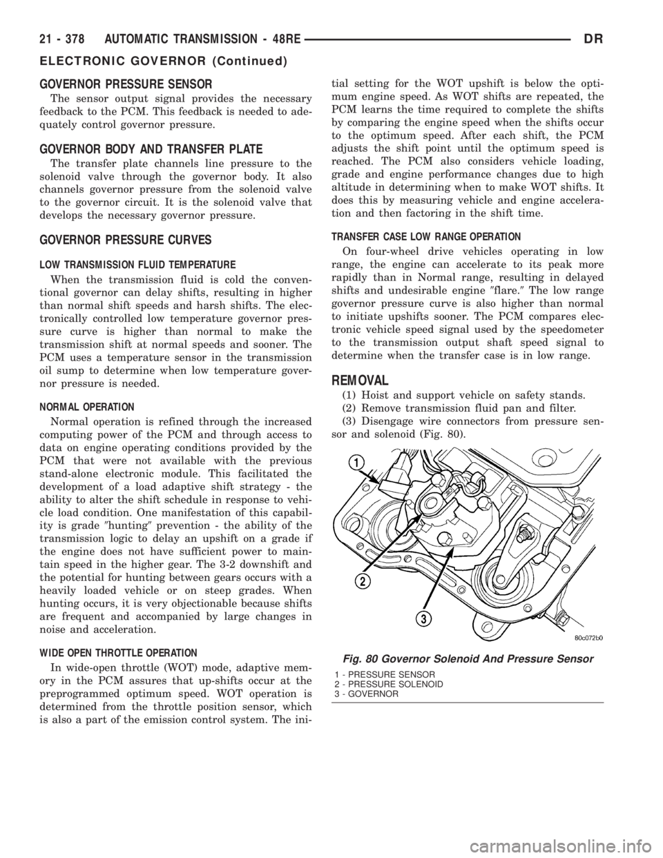
(3) Disengage wire connectors from pressure sen-
sor and solenoid (Fig. 80).
Fig. 80 Governor Solenoid And Pressure Sensor
1 - PRESSURE SENSOR
2 - PRESSURE SOLENOID
3 - GOVERNOR
21 - 378 AUTOMATIC TRANSMISSION - 48REDR
ELECTRONIC GOVERNOR (Continued)
Page 2419 of 2895
control switch is in the OFF position, the clutch will
engage after the shift to third gear.
The TCM controls the torque converter by way of
internal logic software. The programming of the soft-
ware provides the TCM with control over the L/R-CC
Solenoid. There are four output logic states that can
be applied as follows:
²No EMCC
²Partial EMCC
²Full EMCC
²Gradual-to-no EMCC
NO EMCC
Under No EMCC conditions, the L/R Solenoid is
OFF. There are several conditions that can result in
NO EMCC operations. No EMCC can be initiated
due to a fault in the transmission or because the
TCM does not see the need for EMCC under current
driving conditions.
PARTIAL EMCC
Partial EMCC operation modulates the L/R Sole-
noid (duty cycle) to obtain partial torque converter
clutch application. Partial EMCC operation is main-
tained until Full EMCC is called for and actuated.
During Partial EMCC some slip does occur. Partial
EMCC will usually occur at low speeds, low load and
light throttle situations.
FULL EMCC
During Full EMCC operation, the TCM increases
the L/R Solenoid duty cycle to full ON after Partial
EMCC control brings the engine speed within thedesired slip range of transmission input speed rela-
tive to engine rpm.
GRADUAL-TO-NO EMCC
This operation is to soften the change from Full or
Partial EMCC to No EMCC. This is done at mid-
throttle by decreasing the L/R Solenoid duty cycle.
REMOVAL
(1) Remove transmission and torque converter
from vehicle.
(2) Place a suitable drain pan under the converter
housing end of the transmission.
CAUTION: Verify that transmission is secure on the
lifting device or work surface, the center of gravity
of the transmission will shift when the torque con-
verter is removed creating an unstable condition.
The torque converter is a heavy unit. Use caution
when separating the torque converter from the
transmission.
(3) Pull the torque converter forward until the cen-
ter hub clears the oil pump seal.
(4) Separate the torque converter from the trans-
mission.
INSTALLATION
Check converter hub and drive flats for sharp
edges, burrs, scratches, or nicks. Polish the hub and
flats with 320/400 grit paper or crocus cloth if neces-
sary. Verify that the converter hub o-ring is properly
installed and is free from debris. The hub must be
smooth to avoid damaging the pump seal at installa-
tion.
(1) Lubricate oil pump seal lip with transmission
fluid.
(2) Place torque converter in position on transmis-
sion.
CAUTION: Do not damage oil pump seal or con-
verter hub o-ring while inserting torque converter
into the front of the transmission.
(3) Align torque converter to oil pump seal open-
ing.
(4) Insert torque converter hub into oil pump.
(5) While pushing torque converter inward, rotate
converter until converter is fully seated in the oil
pump gears.
(6) Check converter seating with a scale and
straightedge (Fig. 125). Surface of converter lugs
should be at least 13 mm (1/2 in.) to rear of straight-
edge when converter is fully seated.
(7) If necessary, temporarily secure converter with
C-clamp attached to the converter housing.
(8) Install the transmission in the vehicle.
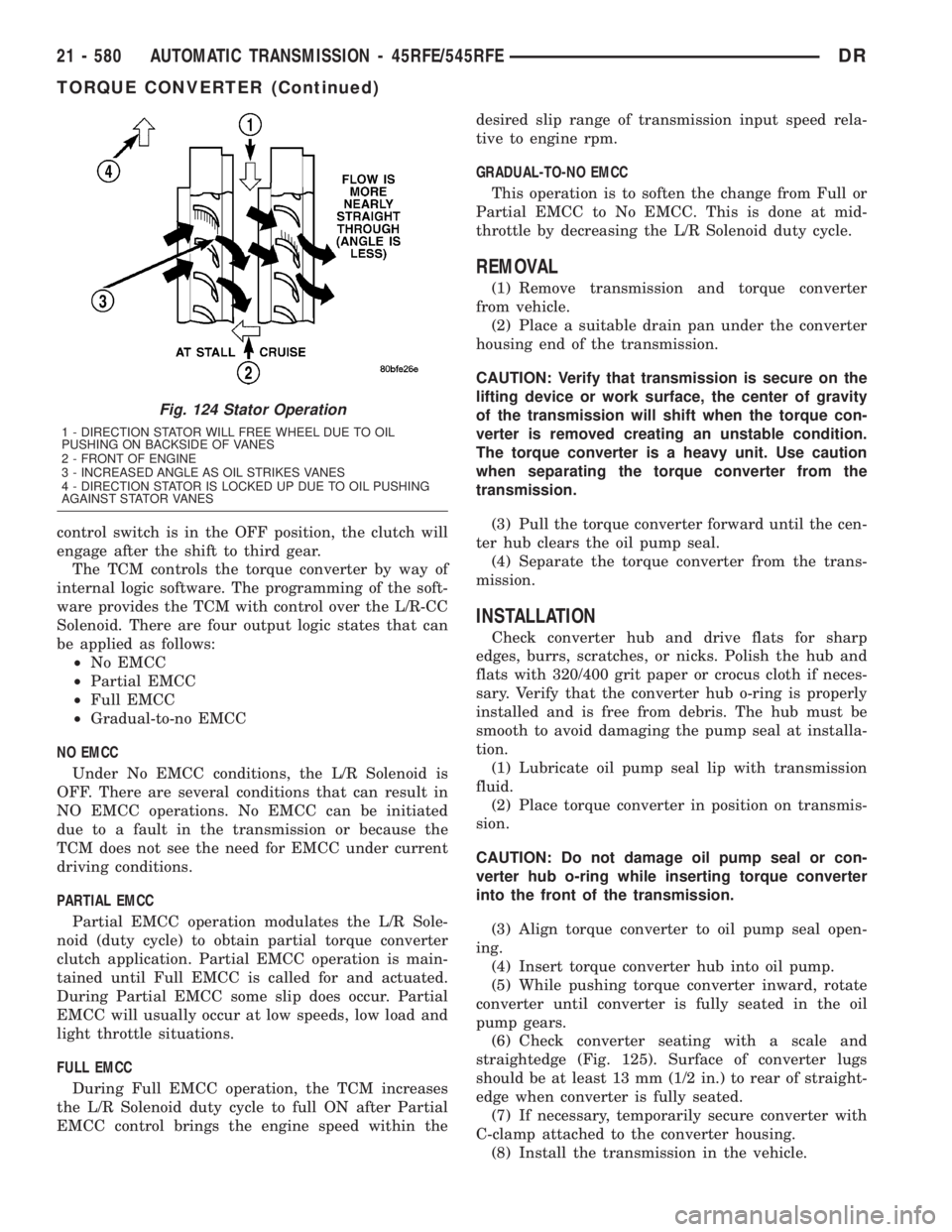
Fig. 124 Stator Operation
1 - DIRECTION STATOR WILL FREE WHEEL DUE TO OIL
PUSHING ON BACKSIDE OF VANES
2 - FRONT OF ENGINE
3 - INCREASED ANGLE AS OIL STRIKES VANES
4 - DIRECTION STATOR IS LOCKED UP DUE TO OIL PUSHING
AGAINST STATOR VANES
21 - 580 AUTOMATIC TRANSMISSION - 45RFE/545RFEDR
TORQUE CONVERTER (Continued)
Page 2497 of 2895
TRANSFER CASE - NV243
TABLE OF CONTENTS
page page
TRANSFER CASE - NV243
DESCRIPTION........................658
OPERATION..........................659
DIAGNOSIS AND TESTING - TRANSFER
CASE - NV243.......................659
REMOVAL............................660
DISASSEMBLY........................660
CLEANING...........................668
INSPECTION.........................668
ASSEMBLY...........................670
INSTALLATION........................679
SPECIFICATIONS
TRANSFER CASE - NV243.............680
SPECIAL TOOLS
TRANSFER CASE - NV241/NV243........680
EXTENSION HOUSING BUSHING AND SEAL
REMOVAL............................682
INSTALLATION........................682FLUID
STANDARD PROCEDURE - FLUID DRAIN AND
REFILL............................682
FRONT OUTPUT SHAFT SEAL
REMOVAL............................683
INSTALLATION........................683
MODE SENSOR
DESCRIPTION........................684
OPERATION..........................684
SELECTOR SWITCH
DESCRIPTION........................685
OPERATION..........................685
SHIFT MOTOR
DESCRIPTION........................686
OPERATION..........................686
REMOVAL............................686
INSTALLATION........................686
TRANSFER CASE - NV243
DESCRIPTION
The NV243 is an electronically controlled part-time
transfer case with a low range gear reduction system.
The NV243 has three operating ranges plus a NEU-
TRAL position. The low range system provides a gear
reduction ratio for increased low speed torque capa-
bility.
The geartrain is mounted in two aluminum case
halves attached with bolts. The mainshaft front and
rear bearings are mounted in aluminum retainer
housings bolted to the case halves.
OPERATING RANGES
Transfer case operating ranges are:
²2WD (2-wheel drive)
²4HI (4-wheel drive)
²4LO (4-wheel drive low range)
²NEUTRAL
The 2WD range is for use on any road surface at
any time.The 4HI and 4LO ranges are for off road use only.
They are not for use on hard surface roads. The only
exception being when the road surface is wet or slip-
pery or covered by ice and snow.
The low range reduction gear system is operative
in 4LO range only. This range is for extra pulling
power in off road situations. Low range reduction
ratio is 2.72:1.
SHIFT MECHANISM
Operating ranges are selected with a dash
mounted shift selector switch. The shift selector
switch provides a input to the Transfer Case Control
Module (TCCM) to indicate the driver's desire to
change operating ranges. The TCCM uses this input,
along with input from the transfer case mounted
mode sensor and information from the vehicle's bus,
to determine if a shift is permitted. If the TCCM
decides the shift is permitted, the TCCM controls the
shift motor, mounted to the exterior of the transfer
case, to perform the shift.
21 - 658 TRANSFER CASE - NV243DR
Page 2526 of 2895
TRANSFER CASE - NV273
TABLE OF CONTENTS
page page
TRANSFER CASE - NV273
DESCRIPTION........................687
OPERATION..........................688
DIAGNOSIS AND TESTING - TRANSFER
CASE - NV273.......................688
REMOVAL............................689
DISASSEMBLY........................689
CLEANING...........................698
INSPECTION.........................699
ASSEMBLY...........................701
INSTALLATION........................713
SPECIFICATIONS
TRANSFER CASE - NV273.............713
SPECIAL TOOLS
TRANSFER CASE NV271/NV273.........714
EXTENSION HOUSING SEAL AND DUST BOOT
REMOVAL............................716
INSTALLATION........................716FLUID
STANDARD PROCEDURE - FLUID DRAIN AND
REFILL............................716
FRONT OUTPUT SHAFT SEAL
REMOVAL............................717
INSTALLATION........................717
MODE SENSOR
DESCRIPTION........................718
OPERATION..........................718
SELECTOR SWITCH
DESCRIPTION........................719
OPERATION..........................719
SHIFT MOTOR
DESCRIPTION........................720
OPERATION..........................720
REMOVAL............................720
INSTALLATION........................720
TRANSFER CASE - NV273
DESCRIPTION
The NV273 is an electronically controlled part-time
transfer case with a low range gear reduction system.
The NV273 has three operating ranges plus a NEU-
TRAL position. The low range system provides a gear
reduction ratio for increased low speed torque capa-
bility.
The geartrain is mounted in two aluminum case
halves attached with bolts. The mainshaft front and
rear bearings are mounted in aluminum case halves.
OPERATING RANGES
Transfer case operating ranges are:
²2WD (2-wheel drive)
²4HI (4-wheel drive)
²4LO (4-wheel drive low range)
²NEUTRAL
The 2WD range is for use on any road surface at
any time.The 4HI and 4LO ranges are for off road use only.
They are not for use on hard surface roads. The only
exception being when the road surface is wet or slip-
pery or covered by ice and snow.
The low range reduction gear system is operative
in 4LO range only. This range is for extra pulling
power in off road situations. Low range reduction
ratio is 2.72:1.
SHIFT MECHANISM
Operating ranges are selected with a dash
mounted shift selector switch. The shift selector
switch provides a input to the Transfer Case Control
Module (TCCM) to indicate the driver's desire to
change operating ranges. The TCCM uses this input,
along with input from the transfer case mounted
mode sensor and information from the vehicle's bus,
to determine if a shift is permitted. If the TCCM
decides the shift is permitted, the TCCM controls the
shift motor, mounted to the exterior of the transfer
case, to perform the shift.
DRTRANSFER CASE - NV273 21 - 687
Page 2566 of 2895

Owners Manual. A Certification Label on the drivers
side door pillar provides the minimum tire and rim size
for the vehicle. The label also list the cold inflation pres-
sure for these tires at full load operation
Tire pressures have been chosen to provide safe
operation, vehicle stability, and a smooth ride. Tire
pressure should be checked cold once a month. Tire
pressure decreases as the ambient temperature
drops. Check tire pressure frequently when ambient
temperature varies widely.
Tire inflation pressures are cold inflation pressure.
The vehicle must sit for at least 3 hours to obtain the
correct cold inflation pressure reading. Or be driven
less than one mile after sitting for 3 hours. Tire
inflation pressures may increase from 2 to 6 pounds
per square inch (psi) during operation. Do not reduce
this normal pressure build-up.
WARNING: OVER OR UNDER INFLATED TIRES CAN
AFFECT VEHICLE HANDLING AND TREAD WEAR.
THIS MAY CAUSE THE TIRE TO FAIL SUDDENLY,
RESULTING IN LOSS OF VEHICLE CONTROL.
DIAGNOSIS AND TESTING
DIAGNOSIS AND TESTING - PRESSURE
GAUGES
A quality air pressure gauge is recommended to
check tire pressure. After checking the air pressure,
replace valve cap finger tight.
DIAGNOSIS AND TESTING - TIRE NOISE OR
VIBRATION
Radial-ply tires are sensitive to force impulses
caused by improper mounting, vibration, wheel
defects, or possibly tire imbalance.
To find out if tires are causing the noise or vibra-
tion, drive the vehicle over a smooth road at varying
speeds. Note the noise level during acceleration and
deceleration. The engine, differential and exhaust
noises will change as speed varies, while the tire
noise will usually remain constant.
DIAGNOSIS AND TESTING - TREAD WEAR
INDICATORS
Tread wear indicators are molded into the bottom
of the tread grooves. When tread depth is 1.6 mm
(1/16 in.), the tread wear indicators will appear as a
13 mm (1/2 in.) band (Fig. 14).
Tire replacement is necessary when indicators
appear in two or more grooves or if localized balding
occurs.
Fig. 12 Under Inflation Wear
1 - THIN TIRE THREAD AREAS
Fig. 13 Over Inflation Wear
1 - THIN TIRE THREAD AREA
Fig. 14 Tread Wear Indicators
1 - TREAD ACCEPTABLE
2 - TREAD UNACCEPTABLE
3 - WEAR INDICATOR
DRTIRES/WHEELS 22 - 7
TIRES (Continued)
Page 2797 of 2895
INSTALLATION
WARNING: ON VEHICLES EQUIPPED WITH AIR-
BAGS, DISABLE THE AIRBAG SYSTEM BEFORE
ATTEMPTING ANY STEERING WHEEL, STEERING
COLUMN, OR INSTRUMENT PANEL COMPONENT
DIAGNOSIS OR SERVICE. DISCONNECT AND ISO-
LATE THE BATTERY NEGATIVE (GROUND) CABLE,
THEN WAIT TWO MINUTES FOR THE AIRBAG SYS-
TEM CAPACITOR TO DISCHARGE BEFORE PER-
FORMING FURTHER DIAGNOSIS OR SERVICE. THIS
IS THE ONLY SURE WAY TO DISABLE THE AIRBAG
SYSTEM. FAILURE TO TAKE THE PROPER PRE-
CAUTIONS COULD RESULT IN ACCIDENTAL AIR-
BAG DEPLOYMENT AND POSSIBLE PERSONAL
INJURY.
(1) Position the mode door actuators onto the heat-
er/AC housing. If necessary, rotate the actuator
slightly to align the splines on the actuator output
shaft with those in the mode door linkage.
(2) Install and tighten the two screws that secure
the mode door actuators to the distribution housing.
Tighten the screws to 2 N´m (17 in. lbs.).
(3) Reconnect the HVAC wire harness connector
for the mode door actuators to the actuator connector
receptacle.
(4) Install the instrument panel assembly(Refer to
23 - BODY/INSTRUMENT PANEL/INSTRUMENT
PANEL ASSEMBLY - INSTALLATION).
(5) Reconnect the battery negative cable.
(6) Perform the heater-A/C control calibration pro-
cedure. (Refer to 24 - HEATING & AIR CONDITION-
ING/CONTROLS - FRONT/A/C-HEATER CONTROL
- STANDARD PROCEDURE - HEATER-A/C CON-
TROL CALIBRATION).
RECIRCULATION DOOR
ACTUATOR
DESCRIPTION
The recirculation door actuator is a reversible,
12-volt Direct Current (DC), servo motor. The single
recirculation door actuator is located on the passen-
ger side end of the heater-A/C housing unit. The
recirculation door actuator is mechanically connected
to the recirculation air door. The recirculation door
actuator is interchangeable with the actuators for the
blend air door(s) and the mode doors. Each actuator
is contained within an identical black molded plastic
housing with an integral wire connector receptacle.
Two integral mounting tabs allow the actuator to be
secured with two screws to the intake air housing.
Each actuator also has an identical output shaft with
splines that connects it to the linkage that drives therecirculation air door. The recirculation door actuator
does not require mechanical indexing to the recircu-
lation air door, as it is electronically calibrated by the
heater-A/C control module. The recirculation door
actuator cannot be adjusted or repaired and, if dam-
aged or faulty, it must be replaced.
OPERATION
The recirculation door actuator is connected to the
heater-A/C control module through the vehicle elec-
trical system by a dedicated two-wire take out and
connector of the HVAC wire harness. The recircula-
tion door actuator can move the recirculation door in
two directions. When the heater-A/C control module
pulls the voltage on one side of the motor connection
high and the other connection low, the recirculation
air door will move in one direction. When the module
reverses the polarity of the voltage to the motor, the
recirculation air door moves in the opposite direction.
When the module makes the voltage to both connec-
tions high or both connections low, the recirculation
air door stops and will not move. These same motor
connections also provide a feedback signal to the
heater-A/C control module. This feedback signal
allows the module to monitor the operation and rela-
tive position of the recirculation door actuator and
the recirculation air door. The heater-A/C control
module learns the recirculation air door stop posi-
tions during the calibration procedure and will store
a Diagnostic Trouble Code (DTC) for any problems it
detects in the recirculation door actuator circuits.
The recirculation door actuator can be diagnosed
using a DRBIIItscan tool. Refer to the appropriate
diagnostic information.
REMOVAL
WARNING: ON VEHICLES EQUIPPED WITH AIR-
BAGS, DISABLE THE AIRBAG SYSTEM BEFORE
ATTEMPTING ANY STEERING WHEEL, STEERING
COLUMN, OR INSTRUMENT PANEL COMPONENT
DIAGNOSIS OR SERVICE. DISCONNECT AND ISO-
LATE THE BATTERY NEGATIVE (GROUND) CABLE,
THEN WAIT TWO MINUTES FOR THE AIRBAG SYS-
TEM CAPACITOR TO DISCHARGE BEFORE PER-
FORMING FURTHER DIAGNOSIS OR SERVICE. THIS
IS THE ONLY SURE WAY TO DISABLE THE AIRBAG
SYSTEM. FAILURE TO TAKE THE PROPER PRE-
CAUTIONS COULD RESULT IN ACCIDENTAL AIR-
BAG DEPLOYMENT AND POSSIBLE PERSONAL
INJURY.
(1) Disconnect and isolate the battery negative
cable.
(2) Pull the carpet on the passenger side front
floor away from the dash panel far enough to access
the recirculation door actuator.
24 - 22 CONTROLSDR
MODE DOOR ACTUATOR (Continued)