2003 DODGE RAM change wheel
[x] Cancel search: change wheelPage 1606 of 2895
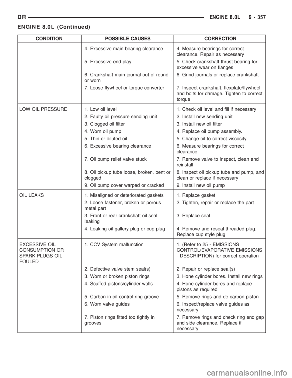
CONDITION POSSIBLE CAUSES CORRECTION
4. Excessive main bearing clearance 4. Measure bearings for correct
clearance. Repair as necessary
5. Excessive end play 5. Check crankshaft thrust bearing for
excessive wear on flanges
6. Crankshaft main journal out of round
or worn6. Grind journals or replace crankshaft
7. Loose flywheel or torque converter 7. Inspect crankshaft, flexplate/flywheel
and bolts for damage. Tighten to correct
torque
LOW OIL PRESSURE 1. Low oil level 1. Check oil level and fill if necessary
2. Faulty oil pressure sending unit 2. Install new sending unit
3. Clogged oil filter 3. Install new oil filter
4. Worn oil pump 4. Replace oil pump assembly.
5. Thin or diluted oil 5. Change oil to correct viscosity.
6. Excessive bearing clearance 6. Measure bearings for correct
clearance
7. Oil pump relief valve stuck 7. Remove valve to inspect, clean and
reinstall
8. Oil pickup tube loose, broken, bent or
clogged8. Inspect oil pickup tube and pump, and
clean or replace if necessary
9. Oil pump cover warped or cracked 9. Install new oil pump
OIL LEAKS 1. Misaligned or deteriorated gaskets 1. Replace gasket
2. Loose fastener, broken or porous
metal part2. Tighten, repair or replace the part
3. Front or rear crankshaft oil seal
leaking3. Replace seal
4. Leaking oil gallery plug or cup plug 4. Remove and reseal threaded plug.
Replace cup style plug
EXCESSIVE OIL
CONSUMPTION OR
SPARK PLUGS OIL
FOULED1. CCV System malfunction 1. (Refer to 25 - EMISSIONS
CONTROL/EVAPORATIVE EMISSIONS
- DESCRIPTION) for correct operation
2. Defective valve stem seal(s) 2. Repair or replace seal(s)
3. Worn or broken piston rings 3. Hone cylinder bores. Install new rings
4. Scuffed pistons/cylinder walls 4. Hone cylinder bores and replace
pistons as required
5. Carbon in oil control ring groove 5. Remove rings and de-carbon piston
6. Worn valve guides 6. Inspect/replace valve guides as
necessary
7. Piston rings fitted too tightly in
grooves7. Remove rings and check ring end gap
and side clearance. Replace if
necessary
DRENGINE 8.0L 9 - 357
ENGINE 8.0L (Continued)
Page 1676 of 2895
CAUTION: Do not reuse damaged fasteners, quality
of repair would be suspect. Failure to use only pro-
duction fasteners or fasteners of equivalent hard-
ness can result in loosening or failure. Do not drill
any holes in the frame that are not specifically out-
lined in this or other, DaimlerChrysler procedure as
frame rail failure can result. When using heat to
straighten frame components do not exceed 566ÉC
(1050ÉF), metal fatigue can result.
NOTE: Procedures for 4X2 and 4X4 are common
except as noted in this procedure.
(1) Disconnect and isolate the battery negative
cable.
(2) Remove the front wheelhouse splash shield.
(Refer to 23 - BODY/EXTERIOR/FRONT WHEEL-
HOUSE SPLASH SHIELD - REMOVAL)
(3) Remove the bolts and position aside the wire
harness and grounds, if required.
(4) Remove the front bumper. (Refer to 13 -
FRAME & BUMPERS/BUMPERS/FRONT BUMPER
- REMOVAL)
(5) Loosen and lower the stabilizer bar mount and
bar. (Refer to 2 - SUSPENSION/FRONT/STABI-
LIZER BAR - REMOVAL)
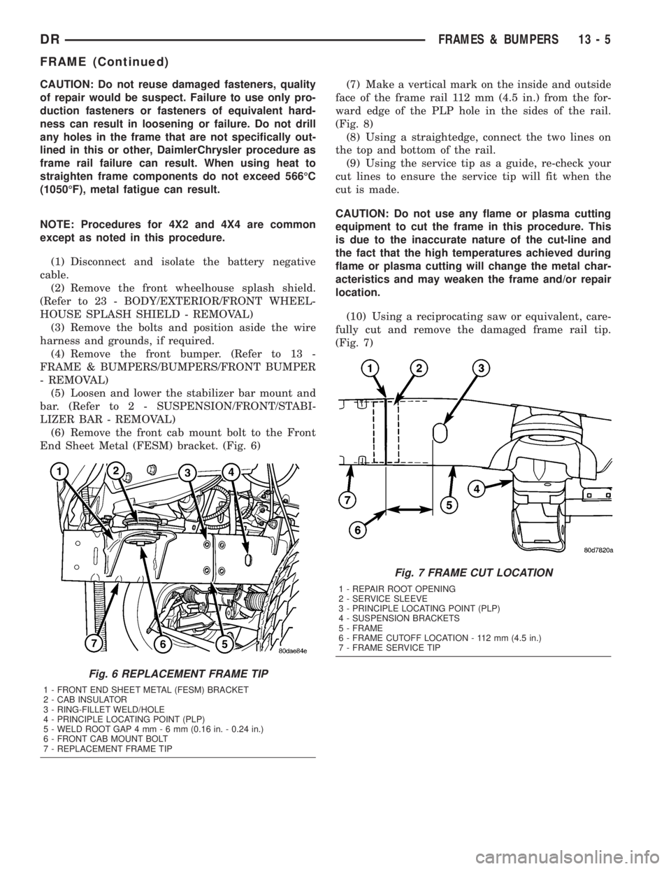
(6) Remove the front cab mount bolt to the Front
End Sheet Metal (FESM) bracket. (Fig. 6)(7) Make a vertical mark on the inside and outside
face of the frame rail 112 mm (4.5 in.) from the for-
ward edge of the PLP hole in the sides of the rail.
(Fig. 8)
(8) Using a straightedge, connect the two lines on
the top and bottom of the rail.
(9) Using the service tip as a guide, re-check your
cut lines to ensure the service tip will fit when the
cut is made.
CAUTION: Do not use any flame or plasma cutting
equipment to cut the frame in this procedure. This
is due to the inaccurate nature of the cut-line and
the fact that the high temperatures achieved during
flame or plasma cutting will change the metal char-
acteristics and may weaken the frame and/or repair
location.
(10) Using a reciprocating saw or equivalent, care-
fully cut and remove the damaged frame rail tip.
(Fig. 7)
Fig. 6 REPLACEMENT FRAME TIP
1 - FRONT END SHEET METAL (FESM) BRACKET
2 - CAB INSULATOR
3 - RING-FILLET WELD/HOLE
4 - PRINCIPLE LOCATING POINT (PLP)
5 - WELD ROOT GAP 4 mm-6mm(0.16 in. - 0.24 in.)
6 - FRONT CAB MOUNT BOLT
7 - REPLACEMENT FRAME TIP
Fig. 7 FRAME CUT LOCATION
1 - REPAIR ROOT OPENING
2 - SERVICE SLEEVE
3 - PRINCIPLE LOCATING POINT (PLP)
4 - SUSPENSION BRACKETS
5 - FRAME
6 - FRAME CUTOFF LOCATION - 112 mm (4.5 in.)
7 - FRAME SERVICE TIP
DRFRAMES & BUMPERS 13 - 5
FRAME (Continued)
Page 1683 of 2895
STANDARD PROCEDURE - HYDROFORM
FENDER RAIL REPAIR
SAFETY PRECAUTIONS AND WARNINGS
WARNING: USE EYE PROTECTION WHEN GRIND-
ING OR WELDING METAL, SERIOUS EYE INJURY
CAN RESULT.
²BEFORE PROCEEDING WITH FRAME REPAIR
INVOLVING GRINDING OR WELDING, VERIFY THAT
VEHICLE FUEL SYSTEM IS NOT LEAKING OR IN
CONTACT WITH REPAIR AREA, PERSONAL INJURY
CAN RESULT.
²DO NOT ALLOW OPEN FLAME OR HEAT AND
METAL SPATTER FROM ARC WELDING, TO CON-
TACT PLASTIC BODY PANELS. FIRE OR EXPLO-
SION CAN RESULT.
²WHEN WELDED FRAME COMPONENTS ARE
REPLACED, ENSURE COMPLETE PENETRATION
WELD IS ACHIEVED DURING INSTALLATION. IF
NOT, DANGEROUS OPERATING CONDITIONS CAN
RESULT.
²STAND CLEAR OF CABLES OR CHAINS ON
PULLING EQUIPMENT DURING FRAME STRAIGHT-
ENING OPERATIONS, PERSONAL INJURY CAN
RESULT.
²DO NOT VENTURE UNDER A HOISTED VEHI-
CLE THAT IS NOT SUPPORTED ON SAFETY
STANDS, PERSONAL INJURY CAN RESULT.
CAUTION: Do not reuse damaged fasteners, quality
of repair would be suspect. Failure to use only pro-
duction fasteners or fasteners of equivalent hard-
ness can result in loosening or failure. Do not drill
holes in top or bottom frame rail flanges, frame rail
failure can result. When using heat to straighten
frame components do not exceed 566ÉC (1050ÉF),
metal fatigue can result.
CAUTION: This repair procedure assumes damage
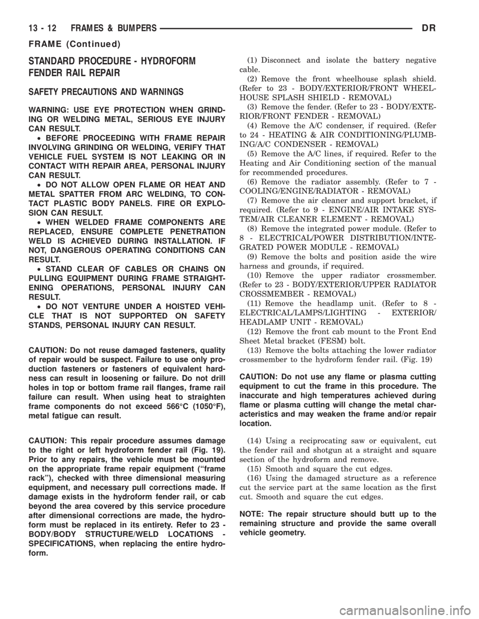
to the right or left hydroform fender rail (Fig. 19).
Prior to any repairs, the vehicle must be mounted
on the appropriate frame repair equipment (ªframe
rackº), checked with three dimensional measuring
equipment, and necessary pull corrections made. If
damage exists in the hydroform fender rail, or cab
beyond the area covered by this service procedure
after dimensional corrections are made, the hydro-
form must be replaced in its entirety. Refer to 23 -
BODY/BODY STRUCTURE/WELD LOCATIONS -
SPECIFICATIONS, when replacing the entire hydro-
form.(1) Disconnect and isolate the battery negative
cable.
(2) Remove the front wheelhouse splash shield.
(Refer to 23 - BODY/EXTERIOR/FRONT WHEEL-
HOUSE SPLASH SHIELD - REMOVAL)
(3) Remove the fender. (Refer to 23 - BODY/EXTE-
RIOR/FRONT FENDER - REMOVAL)
(4) Remove the A/C condenser, if required. (Refer
to 24 - HEATING & AIR CONDITIONING/PLUMB-
ING/A/C CONDENSER - REMOVAL)
(5) Remove the A/C lines, if required. Refer to the
Heating and Air Conditioning section of the manual
for recommended procedures.
(6) Remove the radiator assembly. (Refer to 7 -
COOLING/ENGINE/RADIATOR - REMOVAL)
(7) Remove the air cleaner and support bracket, if
required. (Refer to 9 - ENGINE/AIR INTAKE SYS-
TEM/AIR CLEANER ELEMENT - REMOVAL)
(8) Remove the integrated power module. (Refer to
8 - ELECTRICAL/POWER DISTRIBUTION/INTE-
GRATED POWER MODULE - REMOVAL)
(9) Remove the bolts and position aside the wire
harness and grounds, if required.
(10) Remove the upper radiator crossmember.
(Refer to 23 - BODY/EXTERIOR/UPPER RADIATOR
CROSSMEMBER - REMOVAL)
(11) Remove the headlamp unit. (Refer to 8 -
ELECTRICAL/LAMPS/LIGHTING - EXTERIOR/
HEADLAMP UNIT - REMOVAL)
(12) Remove the front cab mount to the Front End
Sheet Metal bracket (FESM) bolt.
(13) Remove the bolts attaching the lower radiator
crossmember to the hydroform fender rail. (Fig. 19)
CAUTION: Do not use any flame or plasma cutting
equipment to cut the frame in this procedure. The
inaccurate and high temperatures achieved during
flame or plasma cutting will change the metal char-
acteristics and may weaken the frame and/or repair
location.
(14) Using a reciprocating saw or equivalent, cut
the fender rail and shotgun at a straight and square
section of the hydroform and remove.
(15) Smooth and square the cut edges.
(16) Using the damaged structure as a reference
cut the service part at the same location as the first
cut. Smooth and square the cut edges.
NOTE: The repair structure should butt up to the
remaining structure and provide the same overall
vehicle geometry.
13 - 12 FRAMES & BUMPERSDR
FRAME (Continued)
Page 1687 of 2895
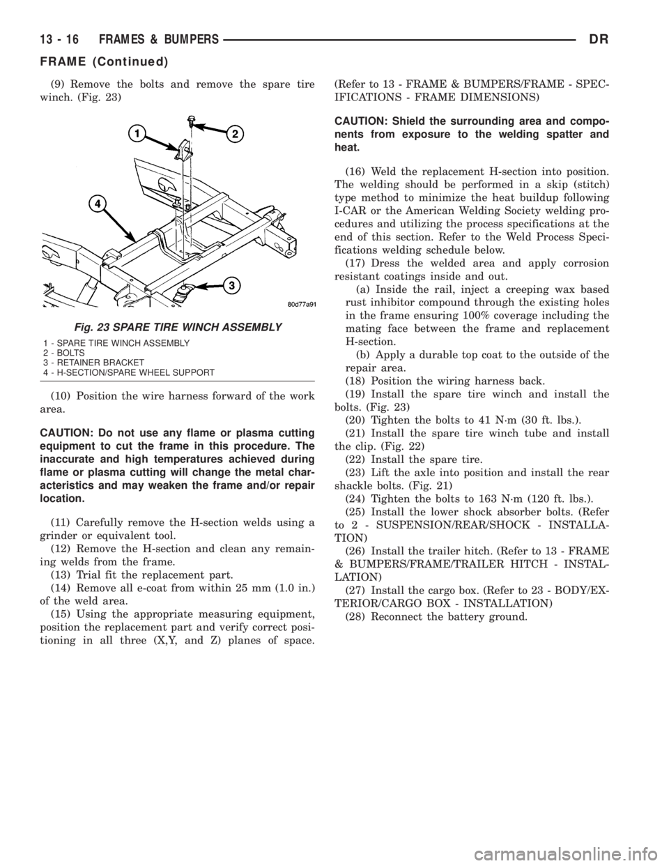
(9) Remove the bolts and remove the spare tire
winch. (Fig. 23)
(10) Position the wire harness forward of the work
area.
CAUTION: Do not use any flame or plasma cutting
equipment to cut the frame in this procedure. The
inaccurate and high temperatures achieved during
flame or plasma cutting will change the metal char-
acteristics and may weaken the frame and/or repair
location.
(11) Carefully remove the H-section welds using a
grinder or equivalent tool.
(12) Remove the H-section and clean any remain-
ing welds from the frame.
(13) Trial fit the replacement part.
(14) Remove all e-coat from within 25 mm (1.0 in.)
of the weld area.
(15) Using the appropriate measuring equipment,
position the replacement part and verify correct posi-
tioning in all three (X,Y, and Z) planes of space.(Refer to 13 - FRAME & BUMPERS/FRAME - SPEC-
IFICATIONS - FRAME DIMENSIONS)
CAUTION: Shield the surrounding area and compo-
nents from exposure to the welding spatter and
heat.
(16) Weld the replacement H-section into position.
The welding should be performed in a skip (stitch)
type method to minimize the heat buildup following
I-CAR or the American Welding Society welding pro-
cedures and utilizing the process specifications at the
end of this section. Refer to the Weld Process Speci-
fications welding schedule below.
(17) Dress the welded area and apply corrosion
resistant coatings inside and out.
(a) Inside the rail, inject a creeping wax based
rust inhibitor compound through the existing holes
in the frame ensuring 100% coverage including the
mating face between the frame and replacement
H-section.
(b) Apply a durable top coat to the outside of the
repair area.
(18) Position the wiring harness back.
(19) Install the spare tire winch and install the
bolts. (Fig. 23)
(20) Tighten the bolts to 41 N´m (30 ft. lbs.).
(21) Install the spare tire winch tube and install
the clip. (Fig. 22)
(22) Install the spare tire.
(23) Lift the axle into position and install the rear
shackle bolts. (Fig. 21)
(24) Tighten the bolts to 163 N´m (120 ft. lbs.).
(25) Install the lower shock absorber bolts. (Refer
to 2 - SUSPENSION/REAR/SHOCK - INSTALLA-
TION)
(26) Install the trailer hitch. (Refer to 13 - FRAME
& BUMPERS/FRAME/TRAILER HITCH - INSTAL-
LATION)
(27) Install the cargo box. (Refer to 23 - BODY/EX-
TERIOR/CARGO BOX - INSTALLATION)
(28) Reconnect the battery ground.
Fig. 23 SPARE TIRE WINCH ASSEMBLY
1 - SPARE TIRE WINCH ASSEMBLY
2 - BOLTS
3 - RETAINER BRACKET
4 - H-SECTION/SPARE WHEEL SUPPORT
13 - 16 FRAMES & BUMPERSDR
FRAME (Continued)
Page 1779 of 2895
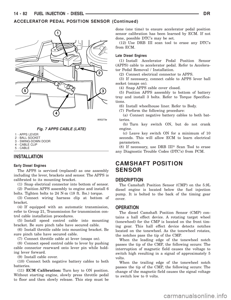
INSTALLATION
Early Diesel Engines
The APPS is serviced (replaced) as one assembly
including the lever, brackets and sensor. The APPS is
calibrated to its mounting bracket.
(1) Snap electrical connector into bottom of sensor.
(2) Position APPS assembly to engine and install 6
bolts. Tighten bolts to 24 N´m (18 ft. lbs.) torque.
(3) Connect wiring harness clip at bottom of
bracket.
(4) If equipped with an automatic transmission,
refer to Group 21, Transmission for transmission con-
trol cable installation procedures.
(5) Install speed control cable into mounting
bracket. Be sure pinch tabs have secured cable.
(6) Install throttle cable into mounting bracket. Be
sure pinch tabs have secured cable.
(7) Connect throttle cable at lever (snaps on).
(8) Connect speed control cable to lever by pushing
cable connector rearward onto lever pin while hold-
ing lever forward.
(9) Install cable cover.
(10) Connect both negative battery cables to both
batteries.
(11)ECM Calibration:Turn key to ON position.
Without starting engine, slowly press throttle pedal
to floor and then slowly release. This step must bedone (one time) to ensure accelerator pedal position
sensor calibration has been learned by ECM. If not
done, possible DTC's may be set.
(12) Use DRB III scan tool to erase any DTC's
from ECM.
Late Diesel Engines
(1) Install Accelerator Pedal Position Sensor
(APPS) cable to accelerator pedal. Refer to Accelera-
tor Pedal Removal / Installation.
(2) Connect electrical connector to APPS.
(3) If necessary, connect cable to APPS lever ball
socket (snaps on).
(4) Snap APPS cable cover closed.
(5) Position APPS assembly to bottom of battery
tray and install 3 bolts. Refer to Torque Specifica-
tions.
(6) Install wheelhouse liner. Refer to Body.
(7) Perform the following procedure:
(a) Connect negative battery cables to both bat-
teries.
(b) Turn key switch ON, but do not crank
engine.
(c) Leave key switch ON for a minimum of 10
seconds. This will allow ECM to learn electrical
parameters.
(8) If necessary, use DRB IIItScan Tool to erase
any Diagnostic Trouble Codes (DTC's) from PCM.CAMSHAFT POSITION
SENSOR
DESCRIPTION
The Camshaft Position Sensor (CMP) on the 5.9L
diesel engine is located below the fuel injection
pump. It is bolted to the back of the timing gear
cover.
OPERATION
The diesel Camshaft Position Sensor (CMP) con-
tains a hall effect device. A rotating target wheel
(tonewheel) for the CMP is located on the front tim-
ing gear. This hall effect device detects notches
located on the tonewheel. As the tonewheel rotates,
the notches pass the tip of the CMP.
When the leading edge of the tonewheel notch
passes the tip of the CMP, the following occurs: The
interruption of magnetic field causes the voltage to
switch high resulting in a signal of approximately 5
volts.
When the trailing edge of the tonewheel notch
passes the tip of the CMP, the following occurs: The
change of the magnetic field causes the signal voltage
to switch low to 0 volts.
Fig. 7 APPS CABLE (LATE)
1 - APPS LEVER
2 - BALL SOCKET
3 - SWING-DOWN DOOR
4 - CABLE CLIP
5 - CABLE
14 - 82 FUEL INJECTION - DIESELDR
ACCELERATOR PEDAL POSITION SENSOR (Continued)
Page 1781 of 2895
tonewheel rotates, the notches pass the tip of the
CKP.
When the leading edge of the tonewheel notch passes
the tip of the CKP, the following occurs: The interrup-
tion of magnetic field causes the voltage to switch high
resulting in a signal of approximately 5 volts.
When the trailing edge of the tonewheel notch
passes the tip of the CKP, the following occurs: The
change of the magnetic field causes the signal voltage
to switch low to 0 volts.
The Camshaft Position Sensor (CMP) also provides
a signal to the Engine Control Module (ECM) at all
times when the engine is running. The ECM uses
this CMP information primarily on engine start-up.
Once the engine is running, the ECM uses the CMP
as a backup sensor for engine speed.
REMOVAL
(1) Raise and support vehicle
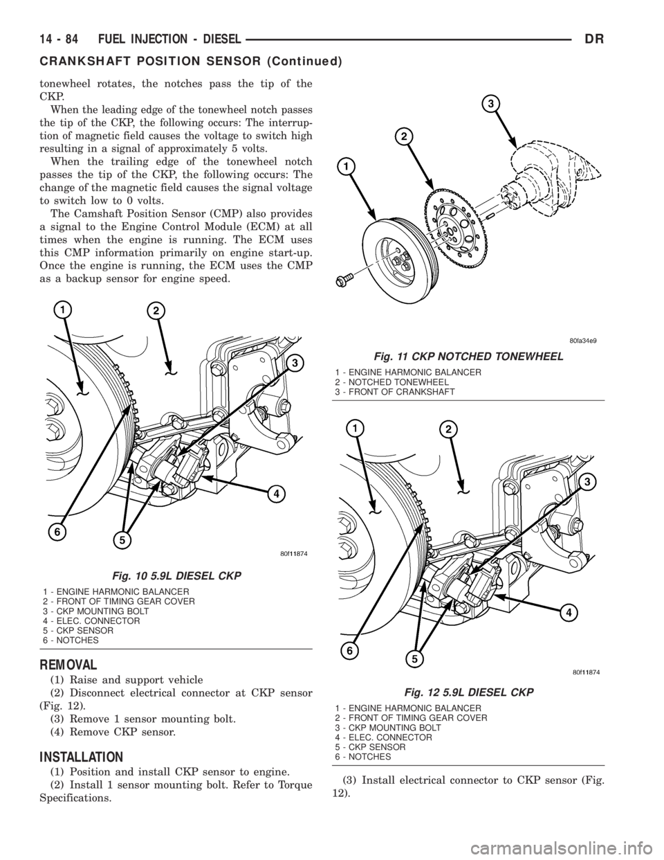
(2) Disconnect electrical connector at CKP sensor
(Fig. 12).
(3) Remove 1 sensor mounting bolt.
(4) Remove CKP sensor.
INSTALLATION
(1) Position and install CKP sensor to engine.
(2) Install 1 sensor mounting bolt. Refer to Torque
Specifications.(3) Install electrical connector to CKP sensor (Fig.
12).
Fig. 10 5.9L DIESEL CKP
1 - ENGINE HARMONIC BALANCER
2 - FRONT OF TIMING GEAR COVER
3 - CKP MOUNTING BOLT
4 - ELEC. CONNECTOR
5 - CKP SENSOR
6 - NOTCHES
Fig. 11 CKP NOTCHED TONEWHEEL
1 - ENGINE HARMONIC BALANCER
2 - NOTCHED TONEWHEEL
3 - FRONT OF CRANKSHAFT
Fig. 12 5.9L DIESEL CKP
1 - ENGINE HARMONIC BALANCER
2 - FRONT OF TIMING GEAR COVER
3 - CKP MOUNTING BOLT
4 - ELEC. CONNECTOR
5 - CKP SENSOR
6 - NOTCHES
14 - 84 FUEL INJECTION - DIESELDR
CRANKSHAFT POSITION SENSOR (Continued)
Page 1794 of 2895
STEERING
TABLE OF CONTENTS
page page
STEERING
DESCRIPTION..........................1
OPERATION............................1
DIAGNOSIS AND TESTING
DIAGNOSIS AND TESTING - POWER
STEERING SYSTEM....................2
DIAGNOSIS AND TESTING - POWER
STEERING FLOW AND PRESSURE........4
SPECIAL TOOLS
STEERING...........................5COLUMN...............................6
GEAR - INDEPENDENT FRONT SUSPENSION..16
GEAR - LINK/COIL.......................19
LINKAGE - INDEPENDENT FRONT
SUSPENSION...........................31
LINKAGE - LINK/COIL....................33
PUMP.................................38
STEERING
DESCRIPTION
CAUTION: MOPARTATF+4 is to be used in the
power steering system. No other power steering or
automatic transmission fluid is to be used in the
system. Damage may result to the power steering
pump and system if any other fluid is used, and do
not overfill.
Power steering systems consist of:
²Steering column
²Rack and pinion steering gear
²Belt driven hydraulic steering pump
²Pump pressure and return hoses
²Oil Cooler
OPERATION
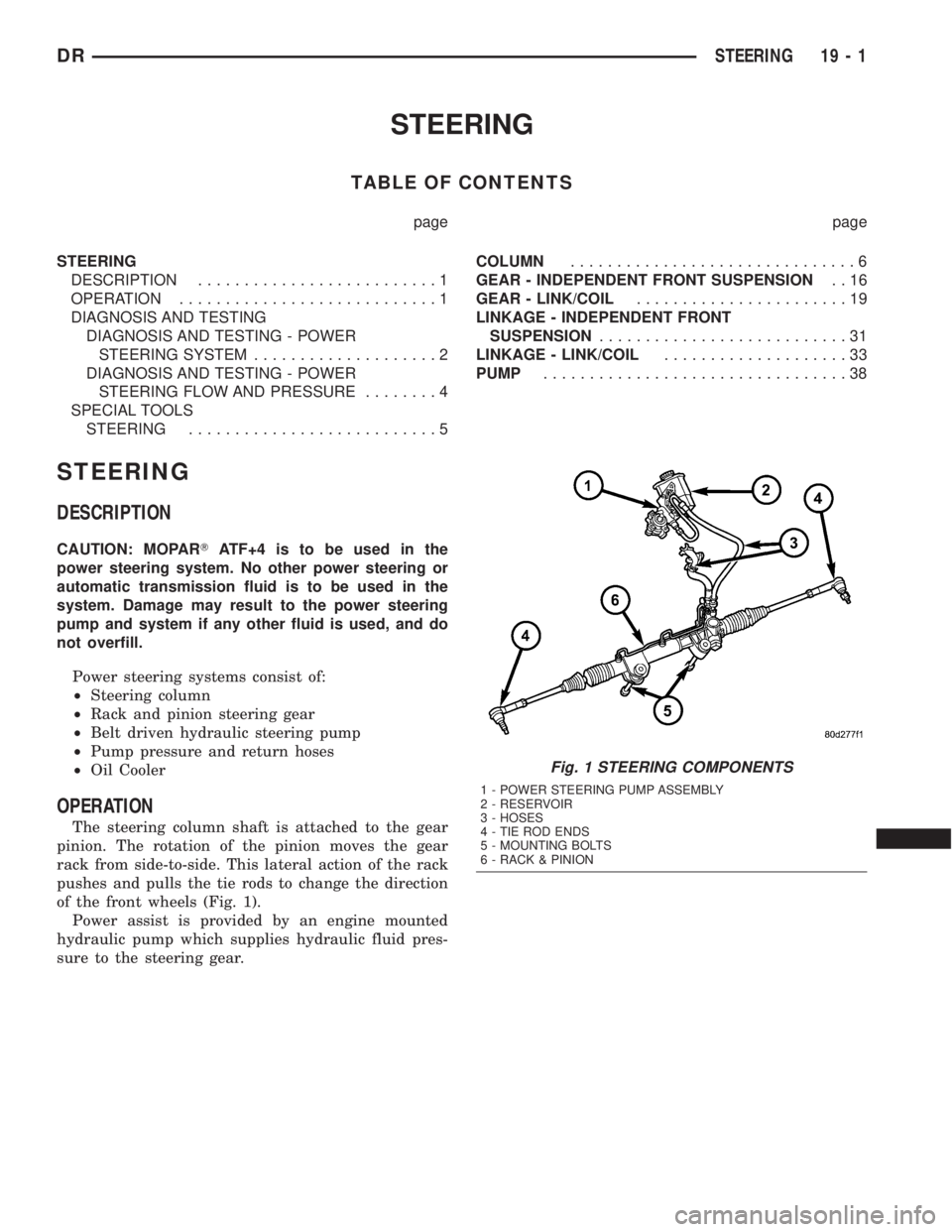
The steering column shaft is attached to the gear
pinion. The rotation of the pinion moves the gear
rack from side-to-side. This lateral action of the rack
pushes and pulls the tie rods to change the direction
of the front wheels (Fig. 1).
Power assist is provided by an engine mounted
hydraulic pump which supplies hydraulic fluid pres-
sure to the steering gear.
Fig. 1 STEERING COMPONENTS
1 - POWER STEERING PUMP ASSEMBLY
2 - RESERVOIR
3 - HOSES
4 - TIE ROD ENDS
5 - MOUNTING BOLTS
6 - RACK & PINION
DRSTEERING 19 - 1
Page 1981 of 2895
Test Four - Transmission In Reverse
This test checks pump output, pressure regulation
and the front clutch and rear servo circuits. Use 300
psi Test Gauge C-3293-SP for this test.
(1) Leave vehicle on hoist and leave gauge C-3292
in place at accumulator port.
(2) Move 300 psi Gauge C-3293-SP back to rear
servo port.
(3) Have helper start and run engine at 1600 rpm
for test.
(4) Move transmission shift lever four detents
rearward from full forward position. This is Reverse
range.
(5) Move transmission throttle lever fully forward
then fully rearward and note reading at Gauge
C-3293-SP.
(6) Pressure should be 145 - 175 psi (1000-1207
kPa) with throttle lever forward and increase to 230 -
280 psi (1586-1931 kPa) as lever is gradually moved
rearward.
Test Five - Governor Pressure
This test checks governor operation by measuring
governor pressure response to changes in vehicle
speed. It is usually not necessary to check governor
operation unless shift speeds are incorrect or if the
transmission will not downshift. The test should be
performed on the road or on a hoist that will allow
the rear wheels to rotate freely.
(1) Move 100 psi Test Gauge C-3292 to governor
pressure port.
(2) Move transmission shift lever two detents rear-
ward from full forward position. This is D range.
(3) Have helper start and run engine at curb idle
speed. Then firmly apply service brakes so wheels
will not rotate.
(4) Note governor pressure:
²Governor pressure should be no more than 20.6
kPa (3 psi) at curb idle speed and wheels not rotat-
ing.
²If pressure exceeds 20.6 kPa (3 psi), a fault
exists in governor pressure control system.
(5) Release brakes, slowly increase engine speed,
and observe speedometer and pressure test gauge (do
not exceed 30 mph on speedometer). Governor pres-
sure should increase in proportion to vehicle speed.
Or approximately 6.89 kPa (1 psi) for every 1 mph.
(6) Governor pressure rise should be smooth and
drop back to no more than 20.6 kPa (3 psi), after
engine returns to curb idle and brakes are applied to
prevent wheels from rotating.
(7) Compare results of pressure test with analysis
chart.Test Six - Transmission In Overdrive Fourth Gear
This test checks line pressure at the overdrive
clutch in fourth gear range. Use 300 psi Test Gauge
C-3293-SP for this test. The test should be performed
on the road or on a chassis dyno.
(1) Remove tachometer; it is not needed for this
test.
(2) Move 300 psi Gauge to overdrive clutch pres-
sure test port. Then remove other gauge and reinstall
test port plug.
(3) Lower vehicle.
(4) Turn OD switch on.
(5) Secure test gauge so it can be viewed from
drivers seat.
(6) Start engine and shift into D range.
(7) Increase vehicle speed gradually until 3-4 shift
occurs and note gauge pressure.
(8) Pressure should be 469-496 kPa (68-72 psi)
with closed throttle and increase to 620-827 kPa (90-
120 psi) at 1/2 to 3/4 throttle. Note that pressure can
increase to around 896 kPa (130 psi) at full throttle.
(9) Return to shop or move vehicle off chassis
dyno.
PRESSURE TEST ANALYSIS CHART
TEST CONDITION INDICATION
Line pressure OK during any
one testPump and regulator valve
OK
Line pressure OK in R but
low in D, 2, 1Leakage in rear clutch area
(seal rings, clutch seals)
Pressure low in D Fourth
Gear RangeOverdrive clutch piston
seal, or check ball problem
Pressure OK in 1, 2 but low
in D3 and RLeakage in front clutch area
Pressure OK in 2 but low in
R and 1Leakage in rear servo
Front servo pressure in 2 Leakage in servo; broken
servo ring or cracked servo
piston
Pressure low in all positions Clogged filter, stuck
regulator valve, worn or
faulty pump, low oil level
Governor pressure too high
at idle speedGovernor pressure solenoid
valve system fault. Refer to
diagnostic book.
Governor pressure low at all
mph figuresFaulty governor pressure
solenoid, transmission
control module, or governor
pressure sensor
Lubrication pressure low at
all throttle positionsClogged fluid cooler or
lines, seal rings leaking,
worn pump bushings,
pump, clutch retainer, or
clogged filter.
Line pressure high Output shaft plugged, sticky
regulator valve
Line pressure low Sticky regulator valve,
clogged filter, worn pump
21 - 142 AUTOMATIC TRANSMISSION - 46REDR
AUTOMATIC TRANSMISSION - 46RE (Continued)