2003 DODGE RAM change wheel
[x] Cancel search: change wheelPage 231 of 2895
and resulting fade can also be caused by riding the
brake pedal, making repeated high deceleration stops
in a short time span, or constant braking on steep
mountain roads. Refer to the Brake Drag information
in this section for causes.
BRAKE PULL
Front brake pull condition could result from:
²Contaminated lining in one caliper
²Seized caliper piston
²Binding caliper
²Loose caliper
²Rusty caliper slide surfaces
²Improper brake shoes
²Damaged rotor
A worn, damaged wheel bearing or suspension
component are further causes of pull. A damaged
front tire (bruised, ply separation) can also cause
pull.
A common and frequently misdiagnosed pull condi-
tion is where direction of pull changes after a few
stops. The cause is a combination of brake drag fol-
lowed by fade at one of the brake units.
As the dragging brake overheats, efficiency is so
reduced that fade occurs. Since the opposite brake
unit is still functioning normally, its braking effect is
magnified. This causes pull to switch direction in
favor of the normally functioning brake unit.
An additional point when diagnosing a change in
pull condition concerns brake cool down. Remember
that pull will return to the original direction, if the
dragging brake unit is allowed to cool down (and is
not seriously damaged).
REAR BRAKE GRAB OR PULL
Rear grab or pull is usually caused by improperly
adjusted or seized parking brake cables, contami-
nated lining, bent or binding shoes and support
plates, or improperly assembled components. This is
particularly true when only one rear wheel is
involved. However, when both rear wheels are
affected, the master cylinder or proportioning valve
could be at fault.
BRAKES DO NOT HOLD AFTER DRIVING THROUGH DEEP
WATER PUDDLES
This condition is generally caused by water soaked
lining. If the lining is only wet, it can be dried by
driving with the brakes very lightly applied for a
mile or two. However, if the lining is both soaked and
dirt contaminated, cleaning and/or replacement will
be necessary.
BRAKE LINING CONTAMINATION
Brake lining contamination is mostly a product of
leaking calipers or wheel cylinders, worn seals, driv-
ing through deep water puddles, or lining that hasbecome covered with grease and grit during repair.
Contaminated lining should be replaced to avoid fur-
ther brake problems.
WHEEL AND TIRE PROBLEMS
Some conditions attributed to brake components
may actually be caused by a wheel or tire problem.
A damaged wheel can cause shudder, vibration and
pull. A worn or damaged tire can also cause pull.
Severely worn tires with very little tread left can
produce a grab-like condition as the tire loses and
recovers traction. Flat-spotted tires can cause vibra-
tion and generate shudder during brake operation. A
tire with internal damage such as a severe bruise,
cut, or ply separation can cause pull and vibration.
BRAKE NOISES
Some brake noise is common with rear drum
brakes and on some disc brakes during the first few
stops after a vehicle has been parked overnight or
stored. This is primarily due to the formation of trace
corrosion (light rust) on metal surfaces. This light
corrosion is typically cleared from the metal surfaces
after a few brake applications causing the noise to
subside.
BRAKE SQUEAK/SQUEAL
Brake squeak or squeal may be due to linings that
are wet or contaminated with brake fluid, grease, or
oil. Glazed linings and rotors with hard spots can
also contribute to squeak. Dirt and foreign material
embedded in the brake lining will also cause squeak/
squeal.
A very loud squeak or squeal is frequently a sign of
severely worn brake lining. If the lining has worn
through to the brake shoes in spots, metal-to-metal
contact occurs. If the condition is allowed to continue,
rotors and drums can become so scored that replace-
ment is necessary.
BRAKE CHATTER
Brake chatter is usually caused by loose or worn
components, or glazed/burnt lining. Rotors with hard
spots can also contribute to chatter. Additional causes
of chatter are out-of-tolerance rotors, brake lining not
securely attached to the shoes, loose wheel bearings
and contaminated brake lining.
THUMP/CLUNK NOISE
Thumping or clunk noises during braking are fre-
quentlynotcaused by brake components. In many
cases, such noises are caused by loose or damaged
steering, suspension, or engine components. However,
calipers that bind on the slide surfaces can generate
a thump or clunk noise. In addition, worn out,
improperly adjusted, or improperly assembled rear
brake shoes can also produce a thump noise.
5 - 4 BRAKES - BASEDR
BRAKES - BASE (Continued)
Page 237 of 2895

(3) Install the brake hose banjo bolt at the caliper
(Fig. 8).
(4) Reinstall the wheel speed sensor wire to the
brake hose (Fig. 8).
(5) Remove the support and lower the vehicle.
(6) Remove the prop rod from the brake pedal.
(7) Bleed the brake system (Refer to 5 - BRAKES -
STANDARD PROCEDURE).
BRAKE PADS/SHOES
REMOVAL
(1) Raise and support vehicle.
(2) Remove the wheel and tire assemblies.
(3) Compress the caliper.
(4) Remove the caliper, (Refer to 5 - BRAKES/HY-
DRAULIC/MECHANICAL/DISC BRAKE CALIPERS
- REMOVAL).
(5) Remove the caliper by tilting the top up and off
the caliper adapter (Fig. 10).
NOTE: Do not allow brake hose to support caliper
assembly.
(6) Support and hang the caliper. (Fig. 11)
(7) Remove the inboard brake shoe from the cali-
per adapter (Fig. 12).
(8) Remove the outboard brake shoe from the cali-
per adapter (Fig. 13).
(9) Remove the anti-rattle springs from the caliper
adapter (Fig. 14) and (Fig. 15).
NOTE: Anti-rattle springs are not interchangeable.
INSTALLATION
(1) Bottom pistons in caliper bore with C-clamp.
Place an old brake shoe between a C-clamp and cal-
iper piston.
(2) Clean caliper mounting adapter and anti-rattle
springs.
(3) Lubricate anti-rattle springs with Mopar brake
grease.
(4) Install anti-rattle springs.
NOTE: Anti-rattle springs are not interchangeable.
(5) Install inboard brake shoe in adapter.
Fig. 9 BRAKE HOSE MOUNT DRIVERS SIDE
1 - MOUNTING BOLT
2 - WHEEL SPEED SENSOR WIRE
3 - BRAKE HOSE
Fig. 10 Caliper
1 - CALIPER
2 - CALIPER ADAPTER
Fig. 11 DISC BRAKE CALIPER - FRONT
1 - STEERING KNUCKLE
2 - DISC BRAKE CALIPER
3 - CALIPER MOUNTING ADAPTER
4 - DISC BRAKE ROTOR
5 - 10 BRAKES - BASEDR
BRAKE LINES (Continued)
Page 251 of 2895
(10) Install the steering column opening cover
(Refer to 23 - BODY/INSTRUMENT PANEL/STEER-
ING COLUMN OPENING COVER - INSTALLA-
TION).
(11) Reconnect the negative battery cable.
ADJUSTABLE PEDAL MOTOR
DESCRIPTION
The Adjustable Pedals System (APS) is designed to
enable the fore and aft repositioning of the brake and
accelerator pedals. This results in improved ergonom-
ics in relation to the steering wheel for taller and
shorter drivers. Being able to adjust the pedal posi-
tions also allows the driver to set steering wheel tilt
and seat position to the most comfortable position.
The position of the brake and accelerator pedals can
be adjusted without compromising safety or comfort
in actuating the pedals.
Change of pedal position is accomplished by means
of a motor driven screw. Operating the adjustable
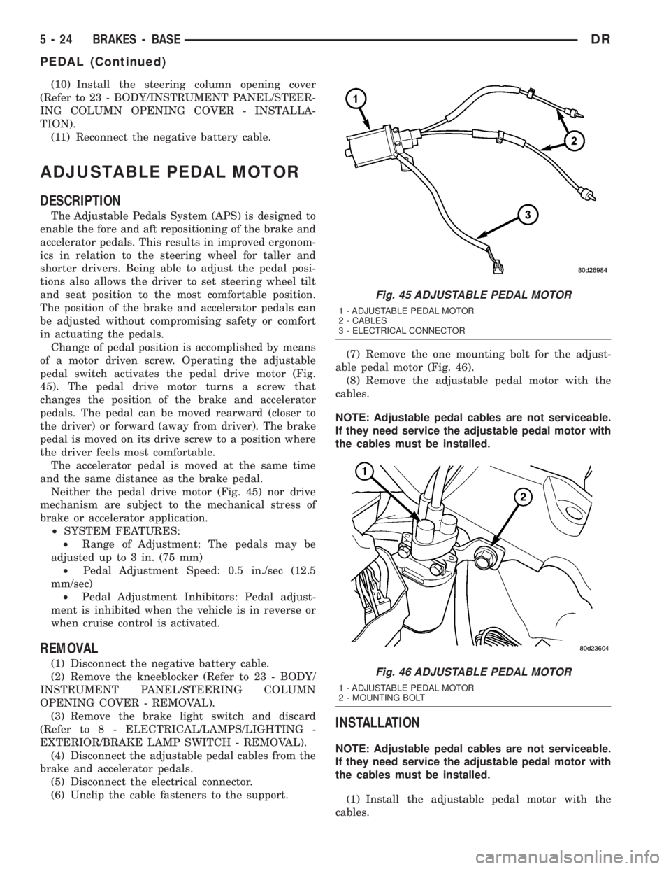
pedal switch activates the pedal drive motor (Fig.
45). The pedal drive motor turns a screw that
changes the position of the brake and accelerator
pedals. The pedal can be moved rearward (closer to
the driver) or forward (away from driver). The brake
pedal is moved on its drive screw to a position where
the driver feels most comfortable.
The accelerator pedal is moved at the same time
and the same distance as the brake pedal.
Neither the pedal drive motor (Fig. 45) nor drive
mechanism are subject to the mechanical stress of
brake or accelerator application.
²SYSTEM FEATURES:
²Range of Adjustment: The pedals may be
adjusted up to 3 in. (75 mm)
²Pedal Adjustment Speed: 0.5 in./sec (12.5
mm/sec)
²Pedal Adjustment Inhibitors: Pedal adjust-
ment is inhibited when the vehicle is in reverse or
when cruise control is activated.
REMOVAL
(1) Disconnect the negative battery cable.
(2) Remove the kneeblocker (Refer to 23 - BODY/
INSTRUMENT PANEL/STEERING COLUMN
OPENING COVER - REMOVAL).
(3) Remove the brake light switch and discard
(Refer to 8 - ELECTRICAL/LAMPS/LIGHTING -
EXTERIOR/BRAKE LAMP SWITCH - REMOVAL).
(4) Disconnect the adjustable pedal cables from the
brake and accelerator pedals.
(5) Disconnect the electrical connector.
(6) Unclip the cable fasteners to the support.(7) Remove the one mounting bolt for the adjust-
able pedal motor (Fig. 46).
(8) Remove the adjustable pedal motor with the
cables.
NOTE: Adjustable pedal cables are not serviceable.
If they need service the adjustable pedal motor with
the cables must be installed.
INSTALLATION
NOTE: Adjustable pedal cables are not serviceable.
If they need service the adjustable pedal motor with
the cables must be installed.
(1) Install the adjustable pedal motor with the
cables.
Fig. 45 ADJUSTABLE PEDAL MOTOR
1 - ADJUSTABLE PEDAL MOTOR
2 - CABLES
3 - ELECTRICAL CONNECTOR
Fig. 46 ADJUSTABLE PEDAL MOTOR
1 - ADJUSTABLE PEDAL MOTOR
2 - MOUNTING BOLT
5 - 24 BRAKES - BASEDR
PEDAL (Continued)
Page 271 of 2895

then opens the outlet valve, which also opens the
return circuit to the accumulators. Fluid pressure is
allowed to bleed off (decrease) as needed to prevent
wheel lock.
Once the period of high wheel slip has ended, the
CAB closes the outlet valve and begins a pressure
increase or hold cycle as needed.
PRESSURE HOLD
Both solenoid valves are closed in the pressure
hold cycle but only the inlet valve is energized. Fluid
apply pressure in the control channel is maintained
at a constant rate. The CAB maintains the hold cycle
until sensor inputs indicate a pressure change is nec-
essary.
PRESSURE INCREASE
The inlet valve is open and the outlet valve is
closed during the pressure increase cycle. The pres-
sure increase cycle is used to reapply thew brakes.
This cycle controls re-application of fluid apply pres-
sure.
REMOVAL
(1) Install a prop rod on the brake pedal to keep
pressure on the brake system.
(2) Disconnect the battery cables from the battery.
(3) Remove the battery.
(4) Disconnect the two electrical harness connec-
tors (Fig. 5).
(5) Remove the five brake lines from the HCU
(Fig. 5).
(6) Remove HCU/CAB mounting bolts and remove
the HCU/CAB (Fig. 5).
INSTALLATION
NOTE: If the CAB is being replaced with a new CAB
is must be reprogrammed with the use of a DRB III.
(1) Install HCU/CAB on the mounts and Tighten
the bolts to 15N´m (11 ft. lbs.) (Fig. 5).
(2) Install the five brake lines to the HCU and
tighten to 19 N´m (170 in. lbs.) (Fig. 5).
(3) Install the two electrical harness connectors to
the HCU/CAB and push down on the release to
secure the connectors.
(4) Install the battery.
(5) Install the battery cables to the battery.
(6) Remove the prop rod on the brake pedal.
(7) Bleed ABS brake system (Refer to 5 - BRAKES
- STANDARD PROCEDURE).
RWAL VALVE
DESCRIPTION
Rear Wheel Antilock (RWAL) brake system is stan-
dard equipment on 1500 series vehicles. The RWAL
brake system is designed to prevent rear wheel
lock-up on virtually all types of road surfaces. RWAL
braking is desirable because a vehicle which is
stopped without locking the rear wheels will retain
directional stability. This allows the driver to retain
greater control of the vehicle during braking.
The valve is located on the drivers side inner
fender under the hood. The valve modulates hydrau-
lic pressure to the rear brakes.
The RWAL components include:
²RWAL Valve
²Controller Antilock brake (CAB)
²Rear Wheel Speed Sensor (WSS)
OPERATION
When the brakes are applied, hydraulic fluid is
routed from the master cylinder's secondary circuit to
the RWAL valve. From there hydraulic fluid is routed
to the rear brakes. The Controller Antilock Brake
(CAB) contains an Electronic Variable Brake Propor-
tioning (EVBP) control algorithm, which proportions
the applied braking force to the rear wheels during
braking. The EVBP function of the RWAL system
takes the place of a conventional hydraulic propor-
tioning valve. The CAB monitors the rear wheel
speed through the rear wheel speed sensor and cal-
culates an estimated vehicle deceleration. When an
established deceleration threshold is exceeded, an
isolation valve is closed to hold the applied brake
pressure to the rear brakes constant. Upon further
increases in the estimated vehicle deceleration, the
isolation valve is selectively opened to increase rear
Fig. 5 HYDRAULIC CONTROL UNIT
1 - HYDRAULIC CONTROL UNIT
2 - MOUNTING BOLTS
5 - 44 BRAKES - ABSDR
HCU (HYDRAULIC CONTROL UNIT) (Continued)
Page 373 of 2895

INSTALLATION
BED TO CAB
(1) Install the ground strap and retaining bolts.
Tighten to 5 N´m (45 in. lbs.).
(2) Connect the battery negative cable.
ENGINE TO HEAT SHIELD
(1) Install the retaining nut and ground strap to
the plenum. Tighten to 8 N´m (70 in. lbs.).
(2) Install the retaining bolt and ground strap to
the engine cylinder heads. Tighten to 12 N´m (106 in.
lbs.).
(3) Connect the battery negative cable.
REMOTE SWITCHES
DESCRIPTION
A remote radio control switch option is available on
some models. Two rocker-type switches are mounted
on the back (instrument panel side) of the steering
wheel spokes (Fig. 13). The switch on the left spoke
is the seek switch and has seek up, seek down, and
preset station advance functions. The switch on the
right spoke is the volume control switch and has vol-
ume up, and volume down functions. The switch on
the right spoke also includes a ªmodeº control that
allows the driver to sequentially select AM radio, FM
radio, cassette player, CD player or CD changer (if
equipped).
OPERATION
The six switches in the two remote radio switch
units are normally open, resistor multiplexed
momentary switches that are hard wired to the Inte-
grated Power Module (IPM) through the clockspring.
The IPM sends a five volt reference signal to both
switch units on one circuit, and senses the status of
all of the switches by reading the voltage drop on a
second circuit.
When the IPM senses an input (voltage drop) from
any one of the remote radio switches, it sends the
proper switch status messages on the Programmable
Communication Interface (PCI) data bus network to
the radio receiver. The electronic circuitry within the
radio receiver is programmed to respond to these
remote radio switch status messages by adjusting the
radio settings as requested. For diagnosis of the IPM
or the PCI data bus, the use of a DRB IIItscan tool
and the proper Diagnostic Procedures manual are
recommended.
For more information on the features and control
functions for each of the remote radio switches, refer
to the owner's manual.
Fig. 12 ENGINE GROUND STRAP - 5.9L (8.0L
SIMILAR)
1 - GROUND STRAP
2 - MOUNTING BOLTS
Fig. 13 Remote Radio Switch Operational View
1 - PRESET SEEK
2 - SEEK UP
3 - VOLUME UP
4 - MODE
5 - VOLUME DOWN
6 - SEEK DOWN
8A - 10 AUDIODR
RADIO NOISE SUPPRESSION GROUND STRAP (Continued)
Page 397 of 2895

²Diagnostic Requests
²Manual Transmission and Brake Applied
²PRNDL
²Ignition Status
²ABS Messages
Once the TCCM determines that a requested shift
is allowed, it actuates the bi-directional shift motor
as necessary to achieve the desired transfer case
operating mode. The TCCM also monitors the mode
sensor while controlling the shift motor to determine
the status of the shift attempt.
Several items can cause the requested shift not to
be completed. If the TCCM has recognized a fault
(DTC) of some variety, it will begin operation in one
of four Functionality Levels. These levels are:
²Level Zero- Normal Operation.
²Level One- Only Mode Shifts Are Allowed.
²Level Two- Only Mode Shifts and Shifts Into
LOW Are Allowed (No Neutral Shifts Are Allowed).
²Level Three- No Shifts Are Allowed
The TCCM can also be operating in one of three
possible power modes. These power modes are:
²Full Power Modeis the normal operational
mode of the module. This mode is achieved by normal
PCI bus traffic being present and the ignition being
in the RUN position.
²Reduced Power Modewill be entered when
the ignition has been powered off. In this state, the
module will shut down power supplied to external
devices, and to electronic interface inputs and out-
puts. From this state the module can enter either
Sleep Mode or Full Power Mode. To enter this mode,
the module must receive an ignition message denot-
ing that the ignition is off, or not receive any mes-
sages for 5 0.5 seconds. To exit this mode, themodule must receive one ignition message that
denotes that the ignition is in the RUN position.
²Sleep Modewill be entered, from the Reduced
Power Mode, when no PCI traffic has been sensed for
20 1 seconds. If during Sleep Mode the module
detects PCI bus traffic, it will revert to the Reduced
Power mode while monitoring for ignition messages.
It will remain in this state as long as there is traffic
other than run or start messages, and will return to
Sleep mode if the bus goes without traffic for 20 1
seconds.
SHIFT REQUIREMENTS
If the TCCM is in full power mode and at function-
ality level zero, it uses the following criteria to deter-
mine if a shift is allowed.
If any of the driver controllable conditions are not
met once the shift request is recognized, the TCCM
will solidly illuminate the source position's LED and
flash the desired position's LED for all shifts except
NEUTRAL. The NEUTRAL shift LED strategy will
be discussed later.
Mode shiftswill be allowed regardless of trans-
mission gear or vehicle speed, whenever the following
conditions are met:
²Front and rear wheel speed are within 21 km/hr
(13 mph).
²A change in the Selector switch state indicates
that a mode shift has been requested.
²A valid mode sensor signal is being sensed by
the TCCM.
²Proper transmit/receive messages are occurring
on the PCI bus.
²Ignition key switch is in the RUN position.
Range shiftswill be allowed only if all of the fol-
lowing conditions are met:
²Front and rear wheel speed are within 21 km/hr
(13 mph).
²A change in the Selector Switch state indicating
a range shift has been requested.
²Transmission in NEUTRAL signal must be rec-
ognized for at least 1.5 seconds 100 msec. (Automat-
ic transmissions only)
²Proper transmit/receive messages are occurring
on the PCI bus.
²Clutch signal is recognized for 500 msec 50
msec (Manual transmissions only).
²Vehicle speed is less than or equal to 4.8 km/hr
(3 miles per hour).
²Ignition key switch is in the RUN position.
²A valid mode sensor signal is being sensed by
the TCCM.
Ashift into transfer case Neutralwill be
allowed only if all of the following conditions are met:
²Front and rear wheel speed are within 21 km/hr
(13 mph).
Fig. 9 Transfer Case Control Module (TCCM)
Location
1 - INSTRUMENT PANEL
2 - TRANSFER CASE CONTROL MODULE (TCCM)
3 - TRANSFER CASE SELECTOR SWITCH
8E - 16 ELECTRONIC CONTROL MODULESDR
TRANSFER CASE CONTROL MODULE (Continued)
Page 453 of 2895
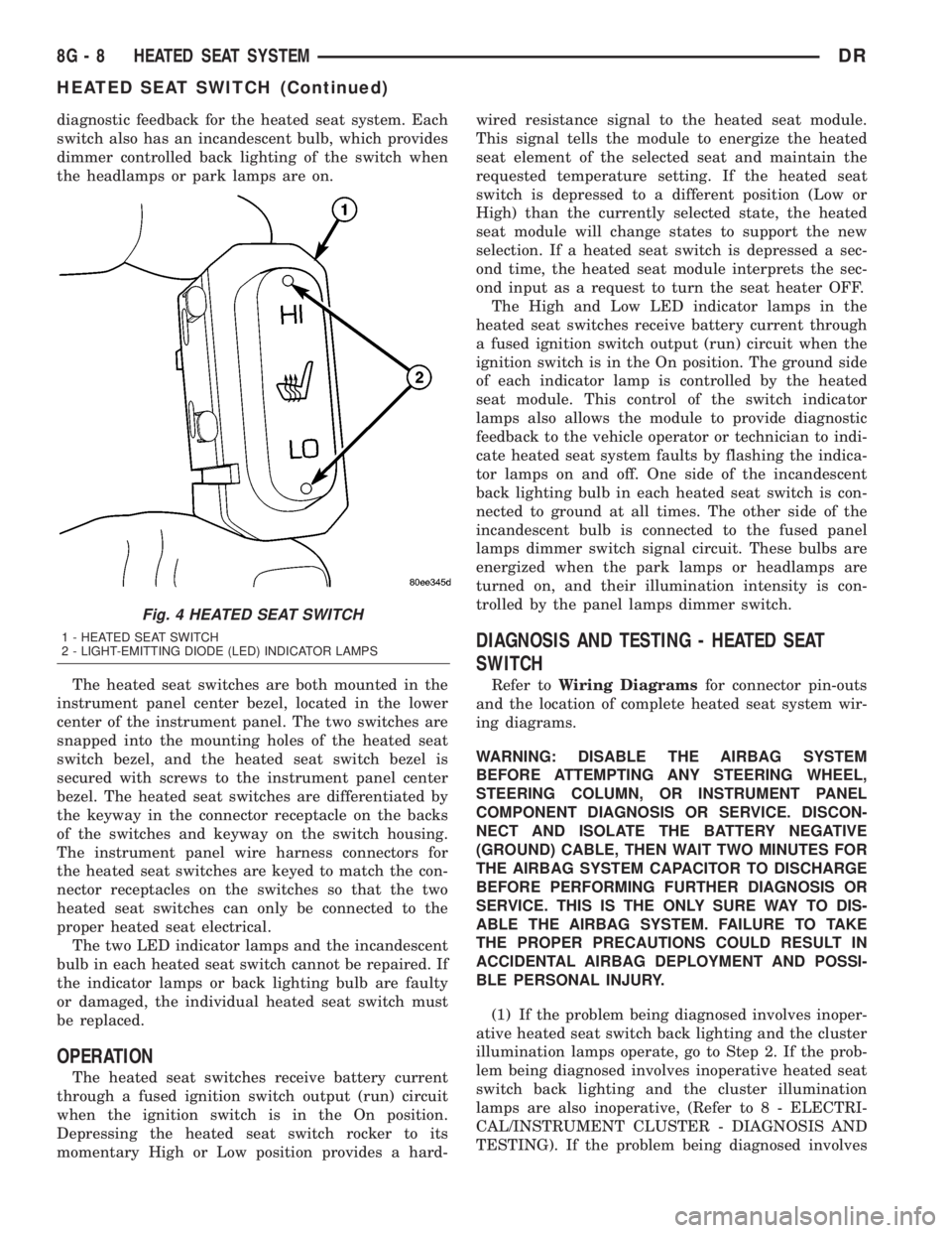
diagnostic feedback for the heated seat system. Each
switch also has an incandescent bulb, which provides
dimmer controlled back lighting of the switch when
the headlamps or park lamps are on.
The heated seat switches are both mounted in the
instrument panel center bezel, located in the lower
center of the instrument panel. The two switches are
snapped into the mounting holes of the heated seat
switch bezel, and the heated seat switch bezel is
secured with screws to the instrument panel center
bezel. The heated seat switches are differentiated by
the keyway in the connector receptacle on the backs
of the switches and keyway on the switch housing.
The instrument panel wire harness connectors for
the heated seat switches are keyed to match the con-
nector receptacles on the switches so that the two
heated seat switches can only be connected to the
proper heated seat electrical.
The two LED indicator lamps and the incandescent
bulb in each heated seat switch cannot be repaired. If
the indicator lamps or back lighting bulb are faulty
or damaged, the individual heated seat switch must
be replaced.
OPERATION
The heated seat switches receive battery current
through a fused ignition switch output (run) circuit
when the ignition switch is in the On position.
Depressing the heated seat switch rocker to its
momentary High or Low position provides a hard-wired resistance signal to the heated seat module.
This signal tells the module to energize the heated
seat element of the selected seat and maintain the
requested temperature setting. If the heated seat
switch is depressed to a different position (Low or
High) than the currently selected state, the heated
seat module will change states to support the new
selection. If a heated seat switch is depressed a sec-
ond time, the heated seat module interprets the sec-
ond input as a request to turn the seat heater OFF.
The High and Low LED indicator lamps in the
heated seat switches receive battery current through
a fused ignition switch output (run) circuit when the
ignition switch is in the On position. The ground side
of each indicator lamp is controlled by the heated
seat module. This control of the switch indicator
lamps also allows the module to provide diagnostic
feedback to the vehicle operator or technician to indi-
cate heated seat system faults by flashing the indica-
tor lamps on and off. One side of the incandescent
back lighting bulb in each heated seat switch is con-
nected to ground at all times. The other side of the
incandescent bulb is connected to the fused panel
lamps dimmer switch signal circuit. These bulbs are
energized when the park lamps or headlamps are
turned on, and their illumination intensity is con-
trolled by the panel lamps dimmer switch.
DIAGNOSIS AND TESTING - HEATED SEAT
SWITCH
Refer toWiring Diagramsfor connector pin-outs
and the location of complete heated seat system wir-
ing diagrams.
WARNING: DISABLE THE AIRBAG SYSTEM
BEFORE ATTEMPTING ANY STEERING WHEEL,
STEERING COLUMN, OR INSTRUMENT PANEL
COMPONENT DIAGNOSIS OR SERVICE. DISCON-
NECT AND ISOLATE THE BATTERY NEGATIVE
(GROUND) CABLE, THEN WAIT TWO MINUTES FOR
THE AIRBAG SYSTEM CAPACITOR TO DISCHARGE
BEFORE PERFORMING FURTHER DIAGNOSIS OR
SERVICE. THIS IS THE ONLY SURE WAY TO DIS-
ABLE THE AIRBAG SYSTEM. FAILURE TO TAKE
THE PROPER PRECAUTIONS COULD RESULT IN
ACCIDENTAL AIRBAG DEPLOYMENT AND POSSI-
BLE PERSONAL INJURY.
(1) If the problem being diagnosed involves inoper-
ative heated seat switch back lighting and the cluster
illumination lamps operate, go to Step 2. If the prob-
lem being diagnosed involves inoperative heated seat
switch back lighting and the cluster illumination
lamps are also inoperative, (Refer to 8 - ELECTRI-
CAL/INSTRUMENT CLUSTER - DIAGNOSIS AND
TESTING). If the problem being diagnosed involves
Fig. 4 HEATED SEAT SWITCH
1 - HEATED SEAT SWITCH
2 - LIGHT-EMITTING DIODE (LED) INDICATOR LAMPS
8G - 8 HEATED SEAT SYSTEMDR
HEATED SEAT SWITCH (Continued)
Page 465 of 2895

(3) Check condition of relay terminals and PDC
connector terminals for damage or corrosion. Repair
if necessary before installing relay.
(4) Check for pin height (pin height should be the
same for all terminals within the PDC connector).
Repair if necessary before installing relay.
INSTALLATION
The ASD relay is located in the Power Distribution
Center (PDC) (Fig. 5). Refer to label on PDC cover
for relay location.
(1) Install relay to PDC.
(2) Install cover to PDC.
CAMSHAFT POSITION
SENSOR
DESCRIPTION
3.7L V-6
The Camshaft Position Sensor (CMP) on the 3.7L
6-cylinder engine is bolted to the right-front side of
the right cylinder head.
4.7L V-8
The Camshaft Position Sensor (CMP) on the 4.7L
V-8 engine is bolted to the right-front side of the
right cylinder head.
5.7L V-8
The Camshaft Position Sensor (CMP) on the 5.7L
V-8 engine is located below the generator on the tim-
ing chain / case cover on the right/front side of
engine.
5.9L Diesel
The Camshaft Position Sensor (CMP) on the 5.9L
diesel engine is located below the fuel injection
pump. It is bolted to the back of the timing gear
cover.
5.9L V-8 Gas
The Camshaft Position Sensor (CMP) on the 5.9L
V-8 engine is located inside the distributor.
8.0L V±10
The Camshaft Position Sensor (CMP) on the 8.0L
V-10 engine is located on the timing chain / case
cover on the left/front side of engine.
OPERATION
3.7L V-6
The Camshaft Position Sensor (CMP) sensor on the
3.7L V-6 engine contains a hall effect device referred
to as a sync signal generator. A rotating target wheel
(tonewheel) for the CMP is located at the front of the
camshaft for the right cylinder head (Fig. 6). This
sync signal generator detects notches located on a
tonewheel. As the tonewheel rotates, the notches
pass through the sync signal generator. The signal
from the CMP sensor is used in conjunction with the
Crankshaft Position Sensor (CKP) to differentiate
between fuel injection and spark events. It is also
used to synchronize the fuel injectors with their
respective cylinders.
When the leading edge of the tonewheel notch
enters the tip of the CMP, the interruption of mag-
netic field causes the voltage to switch high, result-
ing in a sync signal of approximately 5 volts.
When the trailing edge of the tonewheel notch
leaves then tip of the CMP, the change of the mag-
netic field causes the sync signal voltage to switch
low to 0 volts.
4.7L V-8
The CMP sensor on the 4.7L engine contains a hall
effect device called a sync signal generator to gener-
ate a fuel sync signal. This sync signal generator
detects notches located on a tonewheel. The tone-
wheel is located at the front of the camshaft for the
right cylinder head (Fig. 7). As the tonewheel rotates,
the notches pass through the sync signal generator.
The pattern of the notches (viewed counter-clockwise
from front of engine) is: 1 notch, 2 notches, 3 notches,
Fig. 5 PDC LOCATION
1 - BATTERY
2 - PDC (POWER DISTRIBUTION CENTER)
8I - 8 IGNITION CONTROLDR
AUTOMATIC SHUT DOWN RELAY (Continued)