2003 DODGE RAM instrument panel
[x] Cancel search: instrument panelPage 7 of 2895

INTERNATIONAL VEHICLE
CONTROL & DISPLAY
SYMBOLS
DESCRIPTION - INTERNATIONAL SYMBOLS
The graphic symbols illustrated in the following
International Control and Display Symbols Chart are
used to identify various instrument controls. The
symbols correspond to the controls and displays that
are located on the instrument panel.
FASTENER IDENTIFICATION
DESCRIPTION
The SAE bolt strength grades range from grade 2
to grade 8. The higher the grade number, the greater
the bolt strength. Identification is determined by the
line marks on the top of each bolt head. The actual
bolt strength grade corresponds to the number of line
marks plus 2. The most commonly used metric bolt
strength classes are 9.8 and 10.9. The metric
strength class identification number is imprinted on
the head of the bolt. The higher the class number,
the greater the bolt strength. Some metric nuts are
imprinted with a single-digit strength class on the
nut face. Refer to the Fastener Identification and
Fastener Strength Charts (Fig. 6) and (Fig. 7).
INTERNATIONAL SYMBOLS
1 High Beam 13 Rear Window Washer
2 Fog Lamps 14 Fuel
3 Headlamp, Parking Lamps, Panel Lamps 15 Engine Coolant Temperature
4 Turn Warning 16 Battery Charging Condition
5 Hazard Warning 17 Engine Oil
6 Windshield Washer 18 Seat Belt
7 Windshield Wiper 19 Brake Failure
8 Windshield Wiper and Washer 20 Parking Brake
9 Windscreen Demisting and Defrosting 21 Front Hood
10 Ventilating Fan 22 Rear hood (Decklid)
11 Rear Window Defogger 23 Horn
12 Rear Window Wiper 24 Lighter
6 INTRODUCTIONDR
Page 233 of 2895
ADJUSTABLE PEDAL SWITCH
REMOVAL
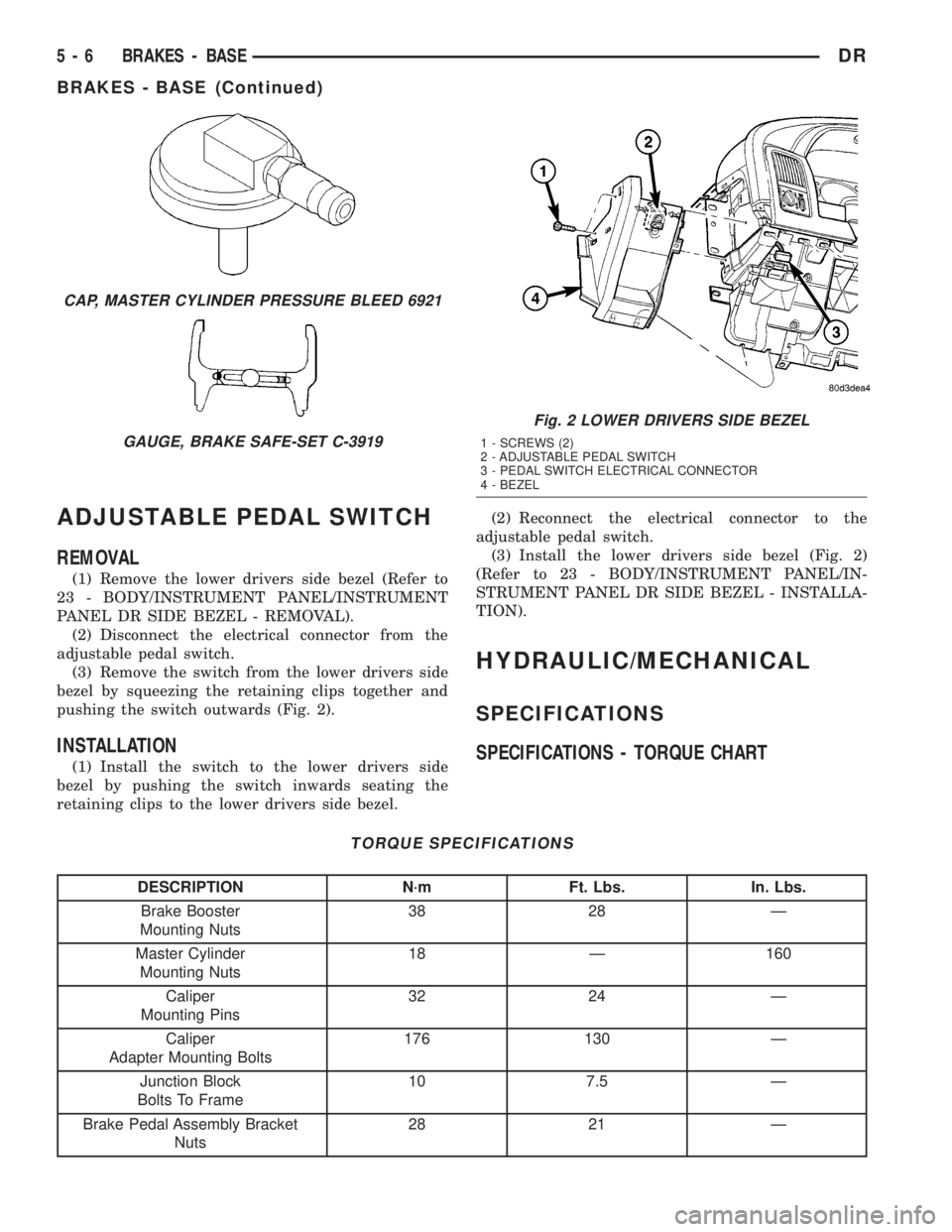
(1) Remove the lower drivers side bezel (Refer to
23 - BODY/INSTRUMENT PANEL/INSTRUMENT
PANEL DR SIDE BEZEL - REMOVAL).
(2) Disconnect the electrical connector from the
adjustable pedal switch.
(3) Remove the switch from the lower drivers side
bezel by squeezing the retaining clips together and
pushing the switch outwards (Fig. 2).
INSTALLATION
(1) Install the switch to the lower drivers side
bezel by pushing the switch inwards seating the
retaining clips to the lower drivers side bezel.(2) Reconnect the electrical connector to the
adjustable pedal switch.
(3) Install the lower drivers side bezel (Fig. 2)
(Refer to 23 - BODY/INSTRUMENT PANEL/IN-
STRUMENT PANEL DR SIDE BEZEL - INSTALLA-
TION).
HYDRAULIC/MECHANICAL
SPECIFICATIONS
SPECIFICATIONS - TORQUE CHART
TORQUE SPECIFICATIONS
DESCRIPTION N´m Ft. Lbs. In. Lbs.
Brake Booster
Mounting Nuts38 28 Ð
Master Cylinder
Mounting Nuts18 Ð 160
Caliper
Mounting Pins32 24 Ð
Caliper
Adapter Mounting Bolts176 130 Ð
Junction Block
Bolts To Frame10 7.5 Ð
Brake Pedal Assembly Bracket
Nuts28 21 Ð
CAP, MASTER CYLINDER PRESSURE BLEED 6921
GAUGE, BRAKE SAFE-SET C-3919
Fig. 2 LOWER DRIVERS SIDE BEZEL
1 - SCREWS (2)
2 - ADJUSTABLE PEDAL SWITCH
3 - PEDAL SWITCH ELECTRICAL CONNECTOR
4 - BEZEL
5 - 6 BRAKES - BASEDR
BRAKES - BASE (Continued)
Page 250 of 2895
REMOVAL
NOTE: The brake pedal is serviced as a complete
assembly including accelerator pedal and the
bracket.
(1) Disconnect the negative battery cable.
(2) Remove the steering column opening cover(Re-
fer to 23 - BODY/INSTRUMENT PANEL/STEERING
COLUMN OPENING COVER - REMOVAL).
(3) Remove the brake lamp switch and discard(Re-
fer to 8 - ELECTRICAL/LAMPS/LIGHTING - EXTE-
RIOR/BRAKE LAMP SWITCH - REMOVAL).
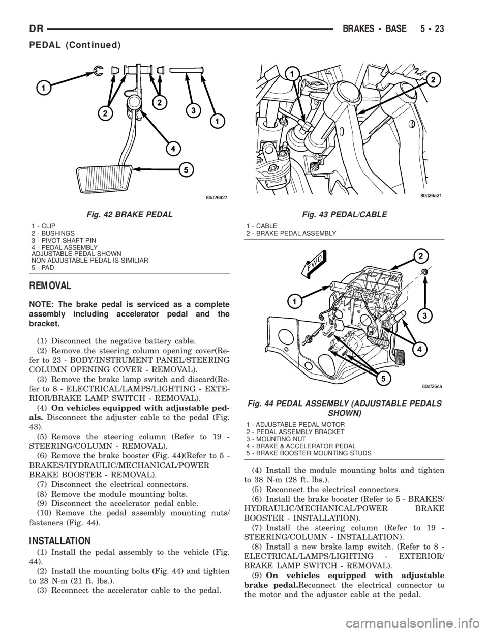
(4)On vehicles equipped with adjustable ped-
als.Disconnect the adjuster cable to the pedal (Fig.
43).
(5) Remove the steering column (Refer to 19 -
STEERING/COLUMN - REMOVAL).
(6) Remove the brake booster (Fig. 44)(Refer to 5 -
BRAKES/HYDRAULIC/MECHANICAL/POWER
BRAKE BOOSTER - REMOVAL).
(7) Disconnect the electrical connectors.
(8) Remove the module mounting bolts.
(9) Disconnect the accelerator pedal cable.
(10) Remove the pedal assembly mounting nuts/
fasteners (Fig. 44).
INSTALLATION
(1) Install the pedal assembly to the vehicle (Fig.
44).
(2) Install the mounting bolts (Fig. 44) and tighten
to 28 N´m (21 ft. lbs.).
(3) Reconnect the accelerator cable to the pedal.(4) Install the module mounting bolts and tighten
to 38 N´m (28 ft. lbs.).
(5) Reconnect the electrical connectors.
(6) Install the brake booster (Refer to 5 - BRAKES/
HYDRAULIC/MECHANICAL/POWER BRAKE
BOOSTER - INSTALLATION).
(7) Install the steering column (Refer to 19 -
STEERING/COLUMN - INSTALLATION).
(8) Install a new brake lamp switch. (Refer to 8 -
ELECTRICAL/LAMPS/LIGHTING - EXTERIOR/
BRAKE LAMP SWITCH - REMOVAL).
(9)On vehicles equipped with adjustable
brake pedal.Reconnect the electrical connector to
the motor and the adjuster cable at the pedal.
Fig. 42 BRAKE PEDAL
1 - CLIP
2 - BUSHINGS
3 - PIVOT SHAFT PIN
4 - PEDAL ASSEMBLY
ADJUSTABLE PEDAL SHOWN
NON ADJUSTABLE PEDAL IS SIMILIAR
5-PAD
Fig. 43 PEDAL/CABLE
1 - CABLE
2 - BRAKE PEDAL ASSEMBLY
Fig. 44 PEDAL ASSEMBLY (ADJUSTABLE PEDALS
SHOWN)
1 - ADJUSTABLE PEDAL MOTOR
2 - PEDAL ASSEMBLY BRACKET
3 - MOUNTING NUT
4 - BRAKE & ACCELERATOR PEDAL
5 - BRAKE BOOSTER MOUNTING STUDS
DRBRAKES - BASE 5 - 23
PEDAL (Continued)
Page 251 of 2895
(10) Install the steering column opening cover
(Refer to 23 - BODY/INSTRUMENT PANEL/STEER-
ING COLUMN OPENING COVER - INSTALLA-
TION).
(11) Reconnect the negative battery cable.
ADJUSTABLE PEDAL MOTOR
DESCRIPTION
The Adjustable Pedals System (APS) is designed to
enable the fore and aft repositioning of the brake and
accelerator pedals. This results in improved ergonom-
ics in relation to the steering wheel for taller and
shorter drivers. Being able to adjust the pedal posi-
tions also allows the driver to set steering wheel tilt
and seat position to the most comfortable position.
The position of the brake and accelerator pedals can
be adjusted without compromising safety or comfort
in actuating the pedals.
Change of pedal position is accomplished by means
of a motor driven screw. Operating the adjustable
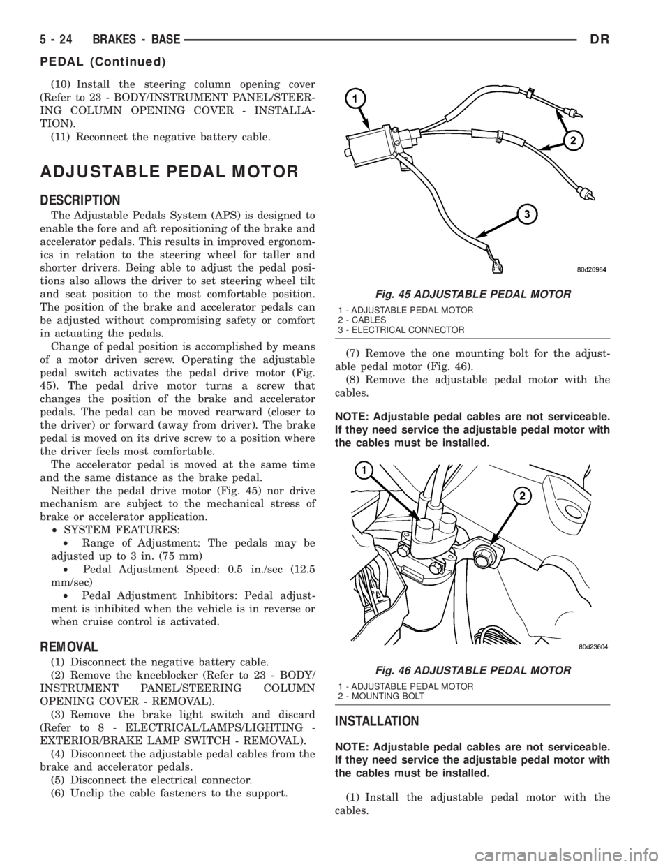
pedal switch activates the pedal drive motor (Fig.
45). The pedal drive motor turns a screw that
changes the position of the brake and accelerator
pedals. The pedal can be moved rearward (closer to
the driver) or forward (away from driver). The brake
pedal is moved on its drive screw to a position where
the driver feels most comfortable.
The accelerator pedal is moved at the same time
and the same distance as the brake pedal.
Neither the pedal drive motor (Fig. 45) nor drive
mechanism are subject to the mechanical stress of
brake or accelerator application.
²SYSTEM FEATURES:
²Range of Adjustment: The pedals may be
adjusted up to 3 in. (75 mm)
²Pedal Adjustment Speed: 0.5 in./sec (12.5
mm/sec)
²Pedal Adjustment Inhibitors: Pedal adjust-
ment is inhibited when the vehicle is in reverse or
when cruise control is activated.
REMOVAL
(1) Disconnect the negative battery cable.
(2) Remove the kneeblocker (Refer to 23 - BODY/
INSTRUMENT PANEL/STEERING COLUMN
OPENING COVER - REMOVAL).
(3) Remove the brake light switch and discard
(Refer to 8 - ELECTRICAL/LAMPS/LIGHTING -
EXTERIOR/BRAKE LAMP SWITCH - REMOVAL).
(4) Disconnect the adjustable pedal cables from the
brake and accelerator pedals.
(5) Disconnect the electrical connector.
(6) Unclip the cable fasteners to the support.(7) Remove the one mounting bolt for the adjust-
able pedal motor (Fig. 46).
(8) Remove the adjustable pedal motor with the
cables.
NOTE: Adjustable pedal cables are not serviceable.
If they need service the adjustable pedal motor with
the cables must be installed.
INSTALLATION
NOTE: Adjustable pedal cables are not serviceable.
If they need service the adjustable pedal motor with
the cables must be installed.
(1) Install the adjustable pedal motor with the
cables.
Fig. 45 ADJUSTABLE PEDAL MOTOR
1 - ADJUSTABLE PEDAL MOTOR
2 - CABLES
3 - ELECTRICAL CONNECTOR
Fig. 46 ADJUSTABLE PEDAL MOTOR
1 - ADJUSTABLE PEDAL MOTOR
2 - MOUNTING BOLT
5 - 24 BRAKES - BASEDR
PEDAL (Continued)
Page 263 of 2895
NOTE: On a new vehicle or after parking brake lin-
ing replacement, it is recommended that the park-
ing brake system be conditioned prior to use. This
is done by making one stop from 25 mph on dry
pavement or concrete using light to moderate force
on the parking brake foot pedal.
(18) Road test the vehicle to ensure proper func-
tion of the vehicle's brake system.
ADJUSTMENT - WITH ADJUSTING TOOL
Adjustment can be made with a standard brake
gauge or with adjusting tool. Adjustment is per-
formed with the complete brake assembly installed
on the backing plate.
(1) Be sure parking brake lever is fully released.
(2) Raise vehicle so rear wheels can be rotated
freely.
(3) Remove plug from each access hole in brake
support plates.
(4) Loosen parking brake cable adjustment nut
until there is slack in front cable.
(5) Insert adjusting tool through support plate
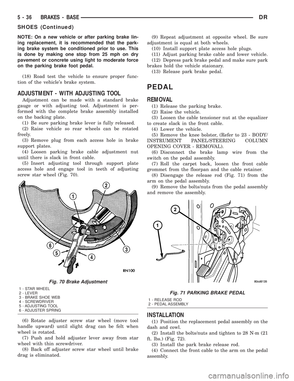
access hole and engage tool in teeth of adjusting
screw star wheel (Fig. 70).
(6) Rotate adjuster screw star wheel (move tool
handle upward) until slight drag can be felt when
wheel is rotated.
(7) Push and hold adjuster lever away from star
wheel with thin screwdriver.
(8) Back off adjuster screw star wheel until brake
drag is eliminated.(9) Repeat adjustment at opposite wheel. Be sure
adjustment is equal at both wheels.
(10) Install support plate access hole plugs.
(11) Adjust parking brake cable and lower vehicle.
(12) Depress park brake pedal and make sure park
brakes hold the vehicle staionary.
(13) Release park brake pedal.
PEDAL
REMOVAL
(1) Release the parking brake.
(2) Raise the vehicle.
(3) Loosen the cable tensioner nut at the equalizer
to create slack in the front cable.
(4) Lower the vehicle.
(5) Remove the knee bolster, (Refer to 23 - BODY/
INSTRUMENT PANEL/STEERING COLUMN
OPENING COVER - REMOVAL).
(6) Disconnect the brake lamp wire from the
switch on the pedal assembly.
(7) Roll the carpet back, loosen the front cable
grommet from the floorpan and the cable retainer.
(8) Disengage the release rod (Fig. 71) from the
arm on the pedal assembly.
(9) Remove the bolts/nuts from the pedal assembly
and remove the assembly.
INSTALLATION
(1) Position the replacement pedal assembly on the
dash and cowl.
(2) Install the bolts/nuts and tighten to 28 N´m (21
ft. lbs.) (Fig. 72).
(3) Install the park brake release rod.
(4) Connect the front cable to the arm on the pedal
assembly.
Fig. 70 Brake Adjustment
1 - STAR WHEEL
2 - LEVER
3 - BRAKE SHOE WEB
4 - SCREWDRIVER
5 - ADJUSTING TOOL
6 - ADJUSTER SPRINGFig. 71 PARKING BRAKE PEDAL
1 - RELEASE ROD
2 - PEDAL ASSEMBLY
5 - 36 BRAKES - BASEDR
SHOES (Continued)
Page 264 of 2895
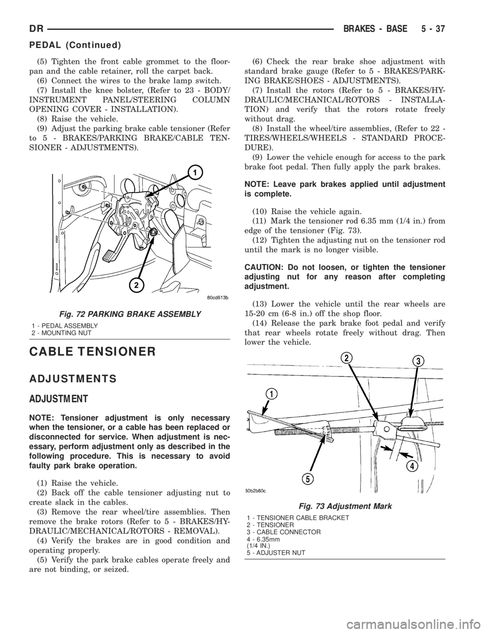
(5) Tighten the front cable grommet to the floor-
pan and the cable retainer, roll the carpet back.
(6) Connect the wires to the brake lamp switch.
(7) Install the knee bolster, (Refer to 23 - BODY/
INSTRUMENT PANEL/STEERING COLUMN
OPENING COVER - INSTALLATION).
(8) Raise the vehicle.
(9) Adjust the parking brake cable tensioner (Refer
to 5 - BRAKES/PARKING BRAKE/CABLE TEN-
SIONER - ADJUSTMENTS).
CABLE TENSIONER
ADJUSTMENTS
ADJUSTMENT
NOTE: Tensioner adjustment is only necessary
when the tensioner, or a cable has been replaced or
disconnected for service. When adjustment is nec-
essary, perform adjustment only as described in the
following procedure. This is necessary to avoid
faulty park brake operation.
(1) Raise the vehicle.
(2) Back off the cable tensioner adjusting nut to
create slack in the cables.
(3) Remove the rear wheel/tire assemblies. Then
remove the brake rotors (Refer to 5 - BRAKES/HY-
DRAULIC/MECHANICAL/ROTORS - REMOVAL).
(4) Verify the brakes are in good condition and
operating properly.
(5) Verify the park brake cables operate freely and
are not binding, or seized.(6) Check the rear brake shoe adjustment with
standard brake gauge (Refer to 5 - BRAKES/PARK-
ING BRAKE/SHOES - ADJUSTMENTS).
(7) Install the rotors (Refer to 5 - BRAKES/HY-
DRAULIC/MECHANICAL/ROTORS - INSTALLA-
TION) and verify that the rotors rotate freely
without drag.
(8) Install the wheel/tire assemblies, (Refer to 22 -
TIRES/WHEELS/WHEELS - STANDARD PROCE-
DURE).
(9) Lower the vehicle enough for access to the park
brake foot pedal. Then fully apply the park brakes.
NOTE: Leave park brakes applied until adjustment
is complete.
(10) Raise the vehicle again.
(11) Mark the tensioner rod 6.35 mm (1/4 in.) from
edge of the tensioner (Fig. 73).
(12) Tighten the adjusting nut on the tensioner rod
until the mark is no longer visible.
CAUTION: Do not loosen, or tighten the tensioner
adjusting nut for any reason after completing
adjustment.
(13) Lower the vehicle until the rear wheels are
15-20 cm (6-8 in.) off the shop floor.
(14) Release the park brake foot pedal and verify
that rear wheels rotate freely without drag. Then
lower the vehicle.
Fig. 72 PARKING BRAKE ASSEMBLY
1 - PEDAL ASSEMBLY
2 - MOUNTING NUT
Fig. 73 Adjustment Mark
1 - TENSIONER CABLE BRACKET
2 - TENSIONER
3 - CABLE CONNECTOR
4 - 6.35mm
(1/4 IN.)
5 - ADJUSTER NUT
DRBRAKES - BASE 5 - 37
PEDAL (Continued)
Page 265 of 2895
RELEASE HANDLE
REMOVAL
(1) Disconnect and isolate the battery negative
cable.
(2) Reach under the driver side outboard end of
the instrument panel to access and unsnap the plas-
tic retainer clip that secures the park brake release
linkage rod to the park brake mechanism on the left
cowl side inner panel.
(3) Disengage the park brake release linkage rod
end from the park brake mechanism.
(4) Lift the park brake release handle to access
and unsnap the plastic retainer clip that secures the
park brake release linkage rod to the lever on the
back of the park brake release handle.
(5) Lower the park brake release handle and reach
under the driver side outboard end of the instrument
panel to disengage the park brake release linkage
rod end from the lever on the back of the park brake
release handle.
(6) Lift the park brake release handle to access the
handle mounting bracket.
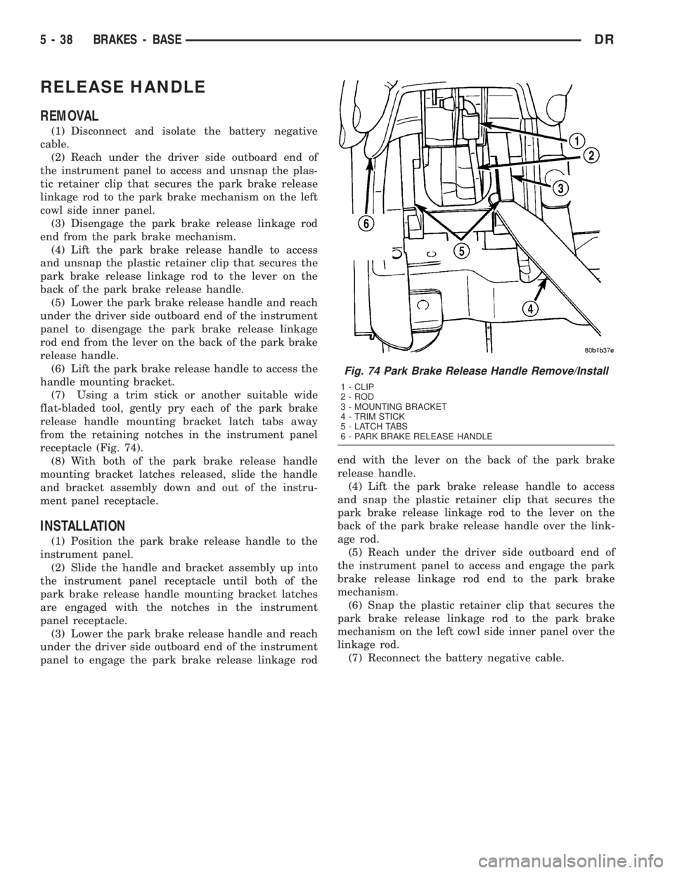
(7) Using a trim stick or another suitable wide
flat-bladed tool, gently pry each of the park brake
release handle mounting bracket latch tabs away
from the retaining notches in the instrument panel
receptacle (Fig. 74).
(8) With both of the park brake release handle
mounting bracket latches released, slide the handle
and bracket assembly down and out of the instru-
ment panel receptacle.
INSTALLATION
(1) Position the park brake release handle to the
instrument panel.
(2) Slide the handle and bracket assembly up into
the instrument panel receptacle until both of the
park brake release handle mounting bracket latches
are engaged with the notches in the instrument
panel receptacle.
(3) Lower the park brake release handle and reach
under the driver side outboard end of the instrument
panel to engage the park brake release linkage rodend with the lever on the back of the park brake
release handle.
(4) Lift the park brake release handle to access
and snap the plastic retainer clip that secures the
park brake release linkage rod to the lever on the
back of the park brake release handle over the link-
age rod.
(5) Reach under the driver side outboard end of
the instrument panel to access and engage the park
brake release linkage rod end to the park brake
mechanism.
(6) Snap the plastic retainer clip that secures the
park brake release linkage rod to the park brake
mechanism on the left cowl side inner panel over the
linkage rod.
(7) Reconnect the battery negative cable.
Fig. 74 Park Brake Release Handle Remove/Install
1 - CLIP
2 - ROD
3 - MOUNTING BRACKET
4 - TRIM STICK
5 - LATCH TABS
6 - PARK BRAKE RELEASE HANDLE
5 - 38 BRAKES - BASEDR
Page 287 of 2895
(6) Install plastic clip securing hydraulic line to
the dash panel into the lower dash panel flange.
(7) Install plastic clip securing hydraulic line to
the dash panel onto the upper dash panel stud.
(8) Raise vehicle.
(9) Install slave cylinder and verify cylinder rod is
properly seated in release lever.
(10) Install and tighten slave cylinder nuts to 23
N´m (17 ft. lbs.).
(11) Ifnewclutch linkage is being installed, con-
nect the clutch hydraulic line to the clutch slave cyl-
inder.
CAUTION: Once the clutch hydraulic line is con-
nected to the slave cylinder, it should never be dis-
connected.
(12) Lower vehicle.
(13) Operate linkage several times to verify proper
operation.
CLUTCH PEDAL POSITION
SWITCH
DESCRIPTION
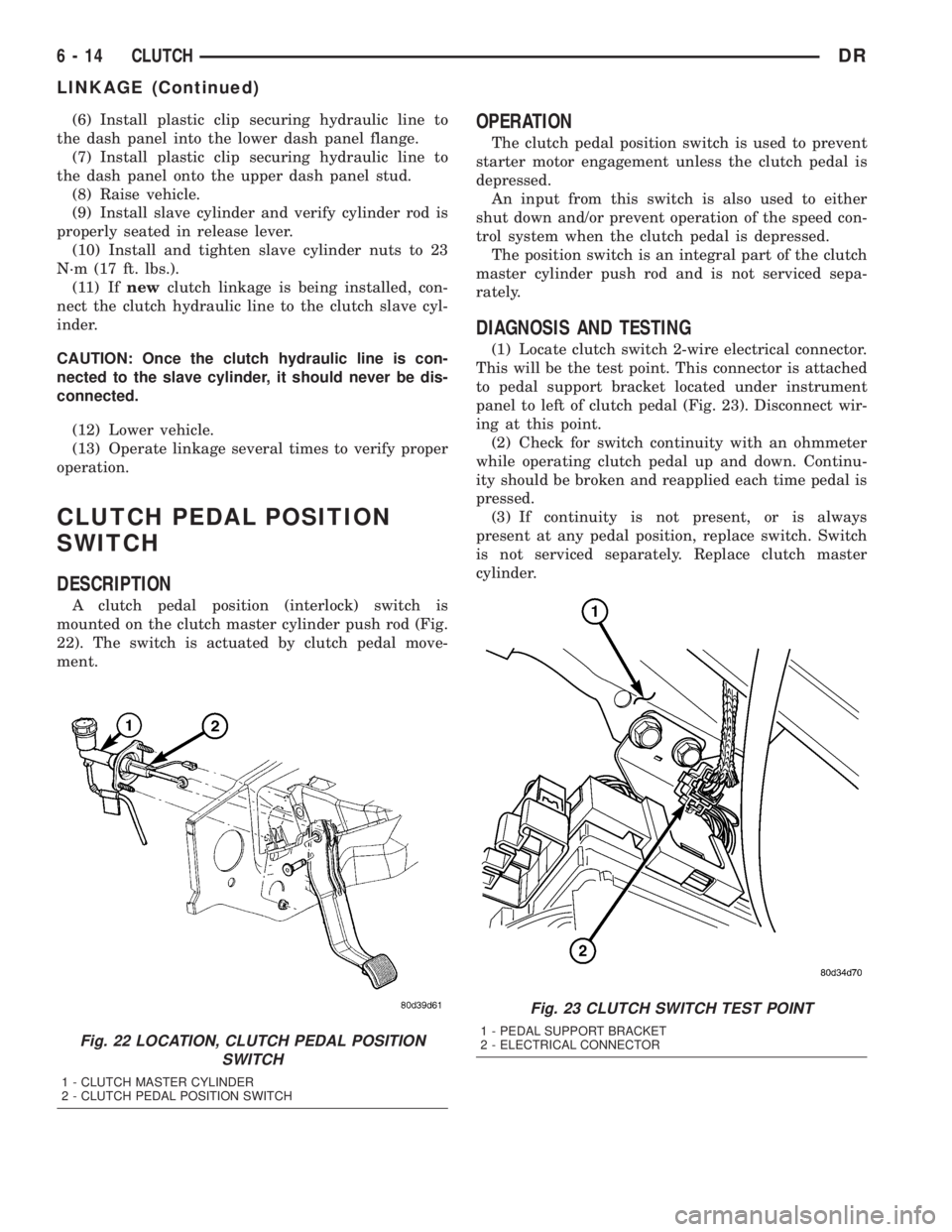
A clutch pedal position (interlock) switch is
mounted on the clutch master cylinder push rod (Fig.
22). The switch is actuated by clutch pedal move-
ment.
OPERATION
The clutch pedal position switch is used to prevent
starter motor engagement unless the clutch pedal is
depressed.
An input from this switch is also used to either
shut down and/or prevent operation of the speed con-
trol system when the clutch pedal is depressed.
The position switch is an integral part of the clutch
master cylinder push rod and is not serviced sepa-
rately.
DIAGNOSIS AND TESTING
(1) Locate clutch switch 2-wire electrical connector.
This will be the test point. This connector is attached
to pedal support bracket located under instrument
panel to left of clutch pedal (Fig. 23). Disconnect wir-
ing at this point.
(2) Check for switch continuity with an ohmmeter
while operating clutch pedal up and down. Continu-
ity should be broken and reapplied each time pedal is
pressed.
(3) If continuity is not present, or is always
present at any pedal position, replace switch. Switch
is not serviced separately. Replace clutch master
cylinder.
Fig. 22 LOCATION, CLUTCH PEDAL POSITION
SWITCH
1 - CLUTCH MASTER CYLINDER
2 - CLUTCH PEDAL POSITION SWITCH
Fig. 23 CLUTCH SWITCH TEST POINT
1 - PEDAL SUPPORT BRACKET
2 - ELECTRICAL CONNECTOR
6 - 14 CLUTCHDR
LINKAGE (Continued)