2003 DODGE RAM airbag
[x] Cancel search: airbagPage 3 of 2895
VEHICLE IDENTIFICATION
NUMBER
DESCRIPTION
VIN CODING/LOCATIONS
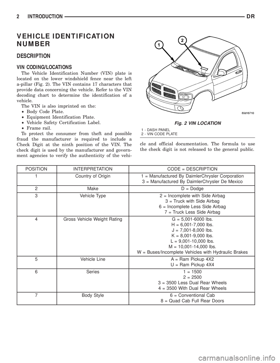
The Vehicle Identification Number (VIN) plate is
located on the lower windshield fence near the left
a-pillar (Fig. 2). The VIN contains 17 characters that
provide data concerning the vehicle. Refer to the VIN
decoding chart to determine the identification of a
vehicle.
The VIN is also imprinted on the:
²Body Code Plate.
²Equipment Identification Plate.
²Vehicle Safety Certification Label.
²Frame rail.
To protect the consumer from theft and possible
fraud the manufacturer is required to include a
Check Digit at the ninth position of the VIN. The
check digit is used by the manufacturer and govern-
ment agencies to verify the authenticity of the vehi-cle and official documentation. The formula to use
the check digit is not released to the general public.
POSITION INTERPRETATION CODE = DESCRIPTION
1 Country of Origin 1 = Manufactured By DaimlerChrysler Corporation
3 = Manufactured By DaimlerChrysler De Mexico
2 Make D = Dodge
3 Vehicle Type 2 = Incomplete with Side Airbag
3 = Truck with Side Airbag
6 = Incomplete Less Side Airbag
7 = Truck Less Side Airbag
4 Gross Vehicle Weight Rating G = 5,001-6000 lbs.
H = 6,001-7,000 lbs.
J = 7,001-8,000 lbs.
K = 8,001-9,000 lbs.
L = 9,001-10,000 lbs.
M = 10,001-14,000 lbs.
W = Buses/Incomplete Vehicles with Hydraulic Brakes
5 Vehicle Line A = Ram Pickup 4X2
U = Ram Pickup 4X4
6 Series 1 = 1500
2 = 2500
3 = 3500 Less Dual Rear Wheels
4 = 3500 With Dual Rear Wheels
7 Body Style 6 = Conventional Cab
8 = Quad Cab Full Rear Doors
Fig. 2 VIN LOCATION
1 - DASH PANEL
2 - VIN CODE PLATE
2 INTRODUCTIONDR
Page 365 of 2895

Instrument Cluster allows it to process those inputs
and send the proper messages to the radio receiver
over the Programmable Communication Interface
(PCI) bus network to control the radio volume up or
down, station seek up or down, preset station
advance, and mode advance functions.
Refer to the owner's manual for more information
on the features, use and operation of each of the
available audio systems.
DIAGNOSIS AND TESTING - AUDIO
Any diagnosis of the Audio system should
begin with the use of the DRB IIItdiagnostic
tool. For information on the use of the DRB
IIIt, refer to the appropriate Diagnostic Service
Manual.
Refer to the appropriate wiring information. The
wiring information includes wiring diagrams, proper
wire and connector repair procedures, details of wireharness routing and retention, connector pin-out
information and location views for the various wire
harness connectors, splices and grounds.
WARNING: DISABLE THE AIRBAG SYSTEM
BEFORE ATTEMPTING ANY STEERING WHEEL,
STEERING COLUMN, SEAT BELT TENSIONER, SIDE
AIRBAG, OR INSTRUMENT PANEL COMPONENT
DIAGNOSIS OR SERVICE. DISCONNECT AND ISO-
LATE THE BATTERY NEGATIVE (GROUND) CABLE,
THEN WAIT TWO MINUTES FOR THE AIRBAG SYS-
TEM CAPACITOR TO DISCHARGE BEFORE PER-
FORMING FURTHER DIAGNOSIS OR SERVICE. THIS
IS THE ONLY SURE WAY TO DISABLE THE AIRBAG
SYSTEM. FAILURE TO TAKE THE PROPER PRE-
CAUTIONS COULD RESULT IN ACCIDENTAL AIR-
BAG DEPLOYMENT AND POSSIBLE PERSONAL
INJURY.
AUDIO SYSTEM DIAGNOSIS TABLE
CONDITION POSSIBLE CAUSES CORRECTION
NO AUDIO 1. Fuse faulty. 1. Check radio fuse and Ignition-Off Draw (IOD)
fuse in the Integrated Power Module (IPM).
Replace fuses, if required.
2. Radio/amplifier (if
equipped) connector faulty.2. Check for loose or corroded radio/amplifier
connector. Repair, if required.
3. Wiring faulty. 3. Check for shorted or open wires. Repair wiring,
if required.
4. Radio/amplifier (if
equipped) ground faulty.4. Check for continuity between radio chassis and
a known good ground. There should be
continuity. Repair ground, if required.
5. Radio/amplifier (if
equipped) faulty.5. Refer to appropriate Diagnostic Service
Manual.
6. Speakers faulty. 6. Replace speaker as necessary.
NO RADIO DISPLAY 1. Fuse faulty. 1. Check radio fuse and Ignition-Off Draw (IOD)
fuse in Integrated Power Module (IPM). Replace
fuses, if required.
2. Radio connector faulty. 2. Check for loose or corroded radio connector.
Repair, if required.
3. Wiring faulty. 3. Check for battery voltage at radio connector.
Repair wiring, if required.
4. Radio ground faulty. 4. Check for continuity between radio chassis and
a known good ground. There should be
continuity. Repair ground, if required.
5. Radio faulty. 5. Refer to appropriate Diagnostic Service
Manual.
8A - 2 AUDIODR
AUDIO (Continued)
Page 367 of 2895
(3) Remove instrument panel center bezel (Refer to
23 - BODY/INSTRUMENT PANEL/INSTRUMENT
PANEL CENTER BEZEL - REMOVAL).
(4) Remove instrument panel lower right center
bezel (Refer to 23 - BODY/INSTRUMENT PANEL/IP
LOWER RIGHT CENTER BEZEL - REMOVAL).
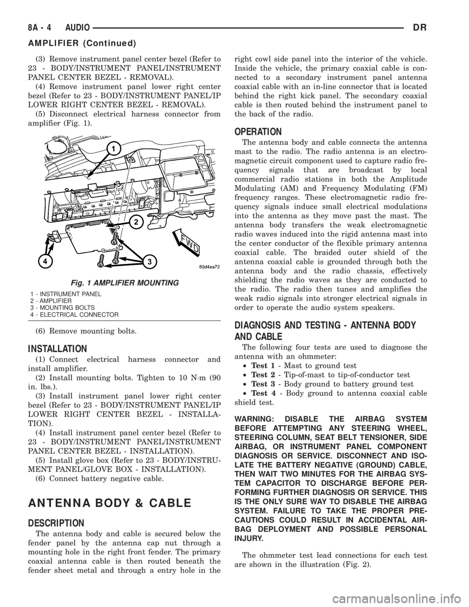
(5) Disconnect electrical harness connector from
amplifier (Fig. 1).
(6) Remove mounting bolts.
INSTALLATION
(1) Connect electrical harness connector and
install amplifier.
(2) Install mounting bolts. Tighten to 10 N´m (90
in. lbs.).
(3) Install instrument panel lower right center
bezel (Refer to 23 - BODY/INSTRUMENT PANEL/IP
LOWER RIGHT CENTER BEZEL - INSTALLA-
TION).
(4) Install instrument panel center bezel (Refer to
23 - BODY/INSTRUMENT PANEL/INSTRUMENT
PANEL CENTER BEZEL - INSTALLATION).
(5) Install glove box (Refer to 23 - BODY/INSTRU-
MENT PANEL/GLOVE BOX - INSTALLATION).
(6) Connect battery negative cable.
ANTENNA BODY & CABLE
DESCRIPTION
The antenna body and cable is secured below the
fender panel by the antenna cap nut through a
mounting hole in the right front fender. The primary
coaxial antenna cable is then routed beneath the
fender sheet metal and through a entry hole in theright cowl side panel into the interior of the vehicle.
Inside the vehicle, the primary coaxial cable is con-
nected to a secondary instrument panel antenna
coaxial cable with an in-line connector that is located
behind the right kick panel. The secondary coaxial
cable is then routed behind the instrument panel to
the back of the radio.
OPERATION
The antenna body and cable connects the antenna
mast to the radio. The radio antenna is an electro-
magnetic circuit component used to capture radio fre-
quency signals that are broadcast by local
commercial radio stations in both the Amplitude
Modulating (AM) and Frequency Modulating (FM)
frequency ranges. These electromagnetic radio fre-
quency signals induce small electrical modulations
into the antenna as they move past the mast. The
antenna body transfers the weak electromagnetic
radio waves induced into the rigid antenna mast into
the center conductor of the flexible primary antenna
coaxial cable. The braided outer shield of the
antenna coaxial cable is grounded through both the
antenna body and the radio chassis, effectively
shielding the radio waves as they are conducted to
the radio. The radio then tunes and amplifies the
weak radio signals into stronger electrical signals in
order to operate the audio system speakers.
DIAGNOSIS AND TESTING - ANTENNA BODY
AND CABLE
The following four tests are used to diagnose the
antenna with an ohmmeter:
²Test 1- Mast to ground test
²Test 2- Tip-of-mast to tip-of-conductor test
²Test 3- Body ground to battery ground test
²Test 4- Body ground to antenna coaxial cable
shield test.
WARNING: DISABLE THE AIRBAG SYSTEM
BEFORE ATTEMPTING ANY STEERING WHEEL,
STEERING COLUMN, SEAT BELT TENSIONER, SIDE
AIRBAG, OR INSTRUMENT PANEL COMPONENT
DIAGNOSIS OR SERVICE. DISCONNECT AND ISO-
LATE THE BATTERY NEGATIVE (GROUND) CABLE,
THEN WAIT TWO MINUTES FOR THE AIRBAG SYS-
TEM CAPACITOR TO DISCHARGE BEFORE PER-
FORMING FURTHER DIAGNOSIS OR SERVICE. THIS
IS THE ONLY SURE WAY TO DISABLE THE AIRBAG
SYSTEM. FAILURE TO TAKE THE PROPER PRE-
CAUTIONS COULD RESULT IN ACCIDENTAL AIR-
BAG DEPLOYMENT AND POSSIBLE PERSONAL
INJURY.
The ohmmeter test lead connections for each test
are shown in the illustration (Fig. 2).
Fig. 1 AMPLIFIER MOUNTING
1 - INSTRUMENT PANEL
2 - AMPLIFIER
3 - MOUNTING BOLTS
4 - ELECTRICAL CONNECTOR
8A - 4 AUDIODR
AMPLIFIER (Continued)
Page 374 of 2895

DIAGNOSIS AND TESTING - REMOTE
SWITCHES
Any diagnosis of the Audio system should
begin with the use of the DRB IIItdiagnostic
tool. For information on the use of the DRB
IIIt, refer to the appropriate Diagnostic Service
Manual.
For complete circuit diagrams, refer to the appro-
priate wiring information. The wiring information
includes wiring diagrams, proper wire and connector
repair procedures, details of wire harness routing
and retention, connector pin-out information and
location views for the various wire harness connec-
tors, splices and grounds.
WARNING: DISABLE THE AIRBAG SYSTEM
BEFORE ATTEMPTING ANY STEERING WHEEL,
STEERING COLUMN, SEAT BELT TENSIONER, SIDE
AIRBAG, OR INSTRUMENT PANEL COMPONENT
DIAGNOSIS OR SERVICE. DISCONNECT AND ISO-
LATE THE BATTERY NEGATIVE (GROUND) CABLE,
THEN WAIT TWO MINUTES FOR THE AIRBAG SYS-
TEM CAPACITOR TO DISCHARGE BEFORE PER-
FORMING FURTHER DIAGNOSIS OR SERVICE. THIS
IS THE ONLY SURE WAY TO DISABLE THE AIRBAG
SYSTEM. FAILURE TO TAKE THE PROPER PRE-
CAUTIONS COULD RESULT IN ACCIDENTAL AIR-
BAG DEPLOYMENT AND POSSIBLE PERSONAL
INJURY.
(1) Disconnect and isolate the battery negative
cable. Remove the remote radio switch(es) (Fig. 14)
from the steering wheel (Refer to 8 - ELECTRICAL/
AUDIO/REMOTE SWITCHES - REMOVAL).(2) Use an ohmmeter to check the switch resis-
tances as shown in the Remote Radio Switch Test
chart. If the remote radio switch resistances check
OK, go to Step 3. If not OK, replace the faulty
switch.
REMOTE RADIO SWITCH TEST TABLE
Switch Switch Position Resistance
Right
(White)Volume Up1.210 Kilohms
1%
Right
(White)Volume Down3.010 Kilohms
1%
Right
(White)Mode Advance0.0511 Kilohms
1%
Left
(Black)Seek Up0.261 Kilohms
1%
Left
(Black)Seek Down0.681 Kilohms
1%
Left
(Black)Pre-Set Station
Advance0.162 Kilohms
1%
(3) Reconnect the battery negative cable. Turn the
ignition switch to the On position. Check for 5 volts
at the radio control mux circuit cavities of the steer-
ing wheel wire harness connectors for both remote
radio switches. If OK, go to Step 4. If not OK, repair
the open or shorted radio control mux circuit to the
Integrated Power Module (IPM) as required.
(4) Disconnect and isolate the battery negative
cable. Disconnect the 22-way instrument panel wire
harness connector from the IPM. Check for continu-
ity between the remote radio switch ground circuit
cavities of the steering wheel wire harness connec-
tors for both remote radio switches and a good
ground. There should be no continuity. If OK, go to
Step 5. If not OK, repair the shorted remote radio
switch ground circuit to the IPM as required.
(5) Check for continuity between the remote radio
switch ground circuit cavities of the steering wheel
wire harness connectors for both remote radio
switches and the 22-way instrument panel wire har-
ness connector for the IPM. There should be continu-
ity. If OK, refer to the proper Diagnostic Procedures
manual to test the IPM and the PCI data bus. If not
OK, repair the open remote radio switch ground cir-
cuit as required.
Fig. 14 Remote Radio Switches
1 - BLACK (LEFT) SWITCH
2 - WHITE (RIGHT) SWITCH
DRAUDIO 8A - 11
REMOTE SWITCHES (Continued)
Page 375 of 2895
REMOVAL
WARNING: DISABLE THE AIRBAG SYSTEM
BEFORE ATTEMPTING ANY STEERING WHEEL,
STEERING COLUMN, SEAT BELT TENSIONER, SIDE
AIRBAG, OR INSTRUMENT PANEL COMPONENT
DIAGNOSIS OR SERVICE. DISCONNECT AND ISO-
LATE THE BATTERY NEGATIVE (GROUND) CABLE,
THEN WAIT TWO MINUTES FOR THE AIRBAG SYS-
TEM CAPACITOR TO DISCHARGE BEFORE PER-
FORMING FURTHER DIAGNOSIS OR SERVICE. THIS
IS THE ONLY SURE WAY TO DISABLE THE AIRBAG
SYSTEM. FAILURE TO TAKE THE PROPER PRE-
CAUTIONS COULD RESULT IN ACCIDENTAL AIR-
BAG DEPLOYMENT AND POSSIBLE PERSONAL
INJURY.
(1) Disconnect and isolate the battery negative
cable.
(2) Remove the driver airbag from the vehicle
(Refer to 8 - ELECTRICAL/RESTRAINTS/DRIVER
AIRBAG - REMOVAL).
(3) Remove the speed control switches (Refer to 8 -
ELECTRICAL/SPEED CONTROL/SWITCH -
REMOVAL).
(4) Unplug the wire harness connector from the
remote radio switch(es).
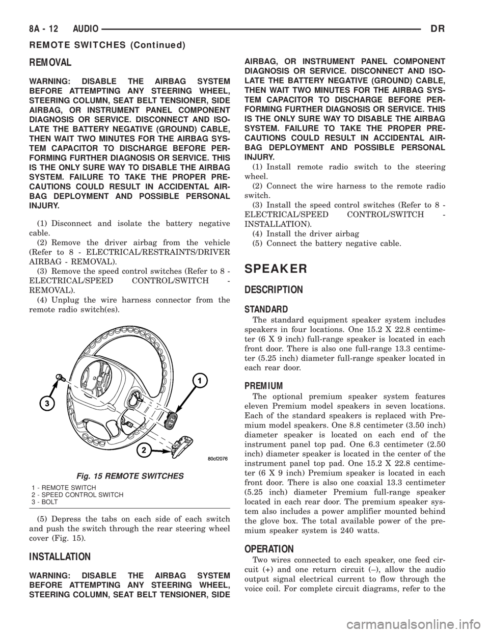
(5) Depress the tabs on each side of each switch
and push the switch through the rear steering wheel
cover (Fig. 15).
INSTALLATION
WARNING: DISABLE THE AIRBAG SYSTEM
BEFORE ATTEMPTING ANY STEERING WHEEL,
STEERING COLUMN, SEAT BELT TENSIONER, SIDEAIRBAG, OR INSTRUMENT PANEL COMPONENT
DIAGNOSIS OR SERVICE. DISCONNECT AND ISO-
LATE THE BATTERY NEGATIVE (GROUND) CABLE,
THEN WAIT TWO MINUTES FOR THE AIRBAG SYS-
TEM CAPACITOR TO DISCHARGE BEFORE PER-
FORMING FURTHER DIAGNOSIS OR SERVICE. THIS
IS THE ONLY SURE WAY TO DISABLE THE AIRBAG
SYSTEM. FAILURE TO TAKE THE PROPER PRE-
CAUTIONS COULD RESULT IN ACCIDENTAL AIR-
BAG DEPLOYMENT AND POSSIBLE PERSONAL
INJURY.
(1) Install remote radio switch to the steering
wheel.
(2) Connect the wire harness to the remote radio
switch.
(3) Install the speed control switches (Refer to 8 -
ELECTRICAL/SPEED CONTROL/SWITCH -
INSTALLATION).
(4) Install the driver airbag
(5) Connect the battery negative cable.
SPEAKER
DESCRIPTION
STANDARD
The standard equipment speaker system includes
speakers in four locations. One 15.2 X 22.8 centime-
ter (6 X 9 inch) full-range speaker is located in each
front door. There is also one full-range 13.3 centime-
ter (5.25 inch) diameter full-range speaker located in
each rear door.
PREMIUM
The optional premium speaker system features
eleven Premium model speakers in seven locations.
Each of the standard speakers is replaced with Pre-
mium model speakers. One 8.8 centimeter (3.50 inch)
diameter speaker is located on each end of the
instrument panel top pad. One 6.3 centimeter (2.50
inch) diameter speaker is located in the center of the
instrument panel top pad. One 15.2 X 22.8 centime-
ter (6 X 9 inch) Premium speaker is located in each
front door. There is also one coaxial 13.3 centimeter
(5.25 inch) diameter Premium full-range speaker
located in each rear door. The premium speaker sys-
tem also includes a power amplifier mounted behind
the glove box. The total available power of the pre-
mium speaker system is 240 watts.
OPERATION
Two wires connected to each speaker, one feed cir-
cuit (+) and one return circuit (±), allow the audio
output signal electrical current to flow through the
voice coil. For complete circuit diagrams, refer to the
Fig. 15 REMOTE SWITCHES
1 - REMOTE SWITCH
2 - SPEED CONTROL SWITCH
3 - BOLT
8A - 12 AUDIODR
REMOTE SWITCHES (Continued)
Page 376 of 2895
appropriate wiring information. The wiring informa-
tion includes wiring diagrams, proper wire and con-
nector repair procedures, details of wire harness
routing and retention, connector pin-out information
and location views for the various wire harness con-
nectors, splices and grounds.
DIAGNOSIS AND TESTING - SPEAKER
Any diagnosis of the Audio system should
begin with the use of the DRB IIItdiagnostic
tool. For information on the use of the DRB
IIIt, refer to the appropriate Diagnostic Service
Manual.
Refer to the appropriate wiring information. The
wiring information includes wiring diagrams, proper
wire and connector repair procedures, details of wire
harness routing and retention, connector pin-out
information and location views for the various wire
harness connectors, splices and grounds.
WARNING: DISABLE THE AIRBAG SYSTEM
BEFORE ATTEMPTING ANY STEERING WHEEL,
STEERING COLUMN, SEAT BELT TENSIONER, SIDE
AIRBAG, OR INSTRUMENT PANEL COMPONENT
DIAGNOSIS OR SERVICE. DISCONNECT AND ISO-
LATE THE BATTERY NEGATIVE (GROUND) CABLE,
THEN WAIT TWO MINUTES FOR THE AIRBAG SYS-
TEM CAPACITOR TO DISCHARGE BEFORE PER-
FORMING FURTHER DIAGNOSIS OR SERVICE. THIS
IS THE ONLY SURE WAY TO DISABLE THE AIRBAG
SYSTEM. FAILURE TO TAKE THE PROPER PRE-
CAUTIONS COULD RESULT IN ACCIDENTAL AIR-
BAG DEPLOYMENT AND POSSIBLE PERSONAL
INJURY.
CAUTION: The speaker output of the radio is a
ªfloating groundº system. Do not allow any speaker
lead to short to ground, as damage to the radio
and/or amplifier may result.
(1) If all speakers are inoperative, check the fuses
in the Integrated Power Module (IPM). If OK, go to
Step 2. If not OK, repair the shorted circuit or com-
ponent as required and replace the faulty fuse.
(2) Check the amplifier fuse (if equipped) in the
IPM. If OK, go to Step 3. If not OK, repair the
shorted circuit or component as required and replace
the faulty fuse.
(3) Turn the ignition switch to the ON position.
Turn the radio receiver ON. Adjust the balance and
fader control controls to check the performance of
each individual speaker. Note the speaker locations
that are not performing correctly. Go to Step 4.
(4) Turn the radio receiver OFF. Turn the ignition
OFF. Disconnect and isolate the battery negativecable. If vehicle isnotequipped with a amplifier,
remove the radio receiver. If vehicle is equipped with
an amplifier. disconnect wire harness connector at
output side of amplifier. Go to Step 5.
(5) Check both the speaker feed (+) circuit and
return (-) circuit cavities for the inoperative speaker
at the radio receiver wire harness connector for con-
tinuity to ground. There should be no continuity. If
OK, go to Step 6. If not OK, repair the shorted
speaker feed (+) and/or return (-) circuits(s) to the
speaker as required.
(6) Disconnect wire harness connector at the inop-
erative speaker. Check for continuity between the
speaker feed (+) circuit cavities of the radio receiver
wire harness connector or if equipped, the amplifier
wire harness connector and the speaker wire harness
connector. Repeat the check between the speaker
return (-) circuit cavities of the radio receiver wire
harness connector and the speaker wire harness con-
nector. In each case, there should be continuity. If
OK, replace the faulty speaker. If not OK, repair the
open speaker feed (+) and/or return (-) circuits(s) as
required.
REMOVAL
FRONT DOOR SPEAKER
(1) Disconnect and isolate the battery negative
cable.
(2) Remove front door trim panel (Refer to 23 -
BODY/DOOR - FRONT/TRIM PANEL - REMOVAL).
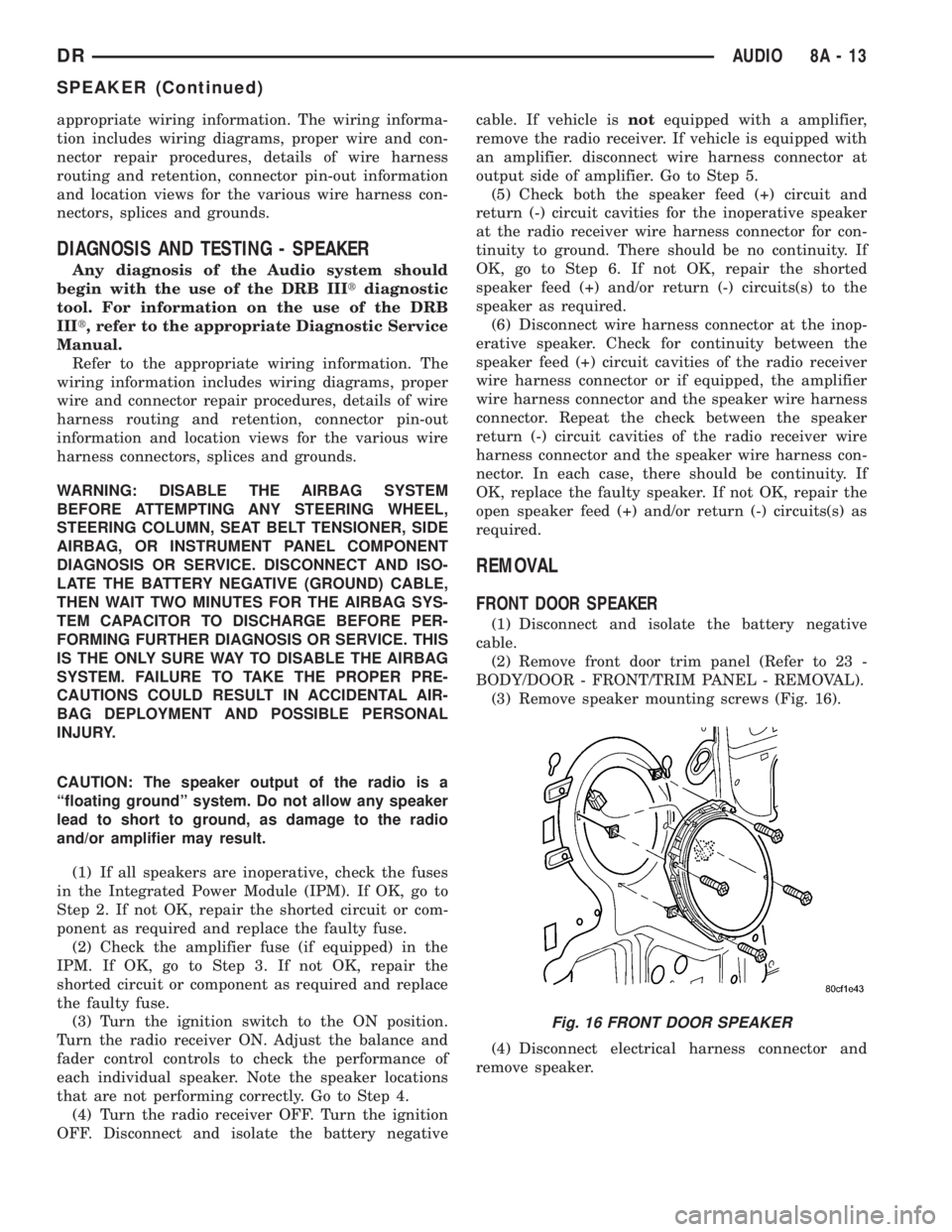
(3) Remove speaker mounting screws (Fig. 16).
(4) Disconnect electrical harness connector and
remove speaker.
Fig. 16 FRONT DOOR SPEAKER
DRAUDIO 8A - 13
SPEAKER (Continued)
Page 435 of 2895
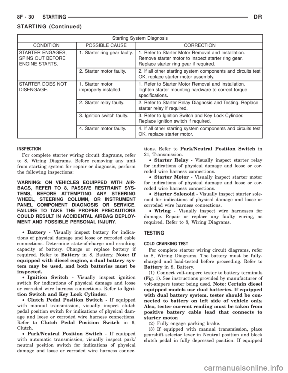
Starting System Diagnosis
CONDITION POSSIBLE CAUSE CORRECTION
STARTER ENGAGES,
SPINS OUT BEFORE
ENGINE STARTS.1. Starter ring gear faulty. 1. Refer to Starter Motor Removal and Installation.
Remove starter motor to inspect starter ring gear.
Replace starter ring gear if required.
2. Starter motor faulty. 2. If all other starting system components and circuits test
OK, replace starter motor assembly.
STARTER DOES NOT
DISENGAGE.1. Starter motor
improperly installed.1. Refer to Starter Motor Removal and Installation.
Tighten starter mounting hardware to correct torque
specifications.
2. Starter relay faulty. 2. Refer to Starter Relay Diagnosis and Testing. Replace
starter relay if required.
3. Ignition switch faulty. 3. Refer to Ignition Switch and Key Lock Cylinder.
Replace ignition switch if required.
4. Starter motor faulty. 4. If all other starting system components and circuits test
OK, replace starter motor.
INSPECTION
For complete starter wiring circuit diagrams, refer
to 8, Wiring Diagrams. Before removing any unit
from starting system for repair or diagnosis, perform
the following inspections:
WARNING: ON VEHICLES EQUIPPED WITH AIR-
BAGS, REFER TO 8, PASSIVE RESTRAINT SYS-
TEMS, BEFORE ATTEMPTING ANY STEERING
WHEEL, STEERING COLUMN, OR INSTRUMENT
PANEL COMPONENT DIAGNOSIS OR SERVICE.
FAILURE TO TAKE THE PROPER PRECAUTIONS
COULD RESULT IN ACCIDENTAL AIRBAG DEPLOY-
MENT AND POSSIBLE PERSONAL INJURY.
²Battery- Visually inspect battery for indica-
tions of physical damage and loose or corroded cable
connections. Determine state-of-charge and cranking
capacity of battery. Charge or replace battery if
required. Refer toBatteryin 8, Battery.Note: If
equipped with diesel engine, a dual battery sys-
tem may be used, and both batteries must be
inspected.
²Ignition Switch- Visually inspect ignition
switch for indications of physical damage and loose
or corroded wire harness connections. Refer toIgni-
tion Switch and Key Lock Cylinder.
²Clutch Pedal Position Switch- If equipped
with manual transmission, visually inspect clutch
pedal position switch for indications of physical dam-
age and loose or corroded wire harness connections.
Refer toClutch Pedal Position Switchin 6,
Clutch.
²Park/Neutral Position Switch- If equipped
with automatic transmission, visually inspect park/
neutral position switch for indications of physical
damage and loose or corroded wire harness connec-tions. Refer toPark/Neutral Position Switchin
21, Transmission.
²Starter Relay- Visually inspect starter relay
for indications of physical damage and loose or cor-
roded wire harness connections.
²Starter Motor- Visually inspect starter motor
for indications of physical damage and loose or cor-
roded wire harness connections.
²Starter Solenoid- Visually inspect starter sole-
noid for indications of physical damage and loose or
corroded wire harness connections.
²Wiring- Visually inspect wire harnesses for
damage. Repair or replace any faulty wiring, as
required. Refer to 8, Wiring Diagrams.
TESTING
COLD CRANKING TEST
For complete starter wiring circuit diagrams, refer
to 8, Wiring Diagrams. The battery must be fully-
charged and load-tested before proceeding. Refer to
Batteryin 8, Battery.
(1) Connect volt-ampere tester to battery terminals
(Fig. 1). See instructions provided by manufacturer of
volt-ampere tester being used.Note: Certain diesel
equipped models use dual batteries. If equipped
with dual battery system, tester should be con-
nected to battery on left side of vehicle only.
Also, tester current reading must be taken from
positive battery cable lead that connects to
starter motor.
(2) Fully engage parking brake.
(3) If equipped with manual transmission, place
gearshift selector lever in Neutral position and block
clutch pedal in fully depressed position. If equipped
8F - 30 STARTINGDR
STARTING (Continued)
Page 447 of 2895

heated mirror switch is depressed and released a sec-
ond time during the same ignition cycle, the elec-
tronic control logic and timer circuitry will
automatically turn the heated mirror system off after
a programmed time interval of about five minutes.
The heated mirror system will be shut off automati-
cally if the ignition switch is turned to the Off or
Accessory positions. After the heated mirror system
is turned On, it can also be turned off manually by
depressing and releasing the heated mirror switch a
second time.
When the heated mirror system is turned On, the
heated mirror system control logic and timer cir-
cuitry energizes the heated mirror system indicator
lamp and the heated mirror relay. When energized,
the heated mirror relay supplies fused ignition
switch output (run/start) current from a fuse in the
JB to the outside mirror heating grids located behind
the mirror glass of each of the outside rear view mir-
rors. When energized, each of the outside mirror
heating grids produces enough heat to warm the
glass of the outside rear view mirrors.
DIAGNOSIS AND TESTING - HEATED MIRROR
SYSTEM
If only one of the outside mirror heating grids is
inoperative, perform continuity checks on the circuits
and heater grid for that mirror only. If both outside
mirror heating grids are inoperative, proceed with
the heated mirror system diagnosis as follows. (Refer
to Appropriate Wiring Information).
WARNING: ON VEHICLES EQUIPPED WITH AIR-
BAGS, DISABLE THE AIRBAG SYSTEM BEFORE
ATTEMPTING ANY STEERING WHEEL, STEERING
COLUMN, OR INSTRUMENT PANEL COMPONENT
DIAGNOSIS OR SERVICE. DISCONNECT AND ISO-
LATE THE BATTERY NEGATIVE (GROUND) CABLE,
THEN WAIT TWO MINUTES FOR THE AIRBAG SYS-
TEM CAPACITOR TO DISCHARGE BEFORE PER-
FORMING FURTHER DIAGNOSIS OR SERVICE. THIS
IS THE ONLY SURE WAY TO DISABLE THE AIRBAG
SYSTEM. FAILURE TO TAKE THE PROPER PRE-
CAUTIONS COULD RESULT IN ACCIDENTAL AIR-
BAG DEPLOYMENT AND POSSIBLE PERSONAL
INJURY.The operation of the heated mirror system can be
confirmed in one of the following manners:
1. Turn the ignition switch to the On position.
While monitoring the instrument panel voltmeter,
momentarily depress and release the heated mirror
switch. When the heated mirror system is turned On,
a distinct voltmeter needle deflection should be
noted.
2. Turn the ignition switch to the On position.
Momentarily depress and release the heated mirror
switch to turn the heated mirror system On. The
heated mirror operation can be checked by feeling
the outside rear view mirror glass. A distinct differ-
ence in temperature between the unheated and
heated mirror glass can be detected within three to
four minutes of system operation.
The above checks will confirm system operation.
Illumination of the heated mirror system indicator
lamp means that there is electrical current available
at the heated mirror relay, but does not confirm that
the electrical current is reaching the outside mirror
heating grids.
If the heated mirror system does not operate, the
problem should be isolated in the following manner:
(1) Confirm that the ignition switch is in the On
position.
(2) Check the fuses in the Power Distribution Cen-
ter (PDC) and in the Junction Block (JB). The fuses
must be tight in their receptacles and all electrical
connections must be secure.
When the above steps have been completed and
both outside mirror heating grids are still inopera-
tive, one or more of the following is faulty:
²Heated mirror switch, electronic control logic
and timer circuitry, and heated mirror relay.
²Heated mirror wire harness circuits or connec-
tors.
²Outside mirror heating grid (both mirror grids
would have to be faulty).
If turning On the heated mirror system produces a
severe voltmeter deflection or fuse failures, check for
a shorted circuit between the output of the heated
mirror relay and the outside mirror heating grids.
8G - 2 HEATED MIRRORSDR
HEATED MIRRORS (Continued)