2003 DODGE RAM parking sensors
[x] Cancel search: parking sensorsPage 512 of 2895

the translucent outer layer of the overlay when the
indicator is illuminated from behind by the LED,
which is soldered onto the instrument cluster elec-
tronic circuit board. The brake indicator is serviced
as a unit with the instrument cluster.
OPERATION
The brake indicator gives an indication to the vehi-
cle operator when the parking brake is applied, when
there are certain brake hydraulic system malfunc-
tions as indicated by a low brake hydraulic fluid level
condition, or when the brake fluid level switch is dis-
connected. The brake indicator can also give an indi-
cation when certain faults are detected in the
Antilock Brake System (ABS). This indicator is con-
trolled by a transistor on the instrument cluster cir-
cuit board based upon cluster programming,
electronic messages received by the cluster from the
Controller Antilock Brake (CAB) over the Program-
mable Communications Interface (PCI) data bus, and
a hard wired input from the park brake switch. The
brake indicator Light Emitting Diode (LED) is com-
pletely controlled by the instrument cluster logic cir-
cuit, and that logic will only allow this indicator to
operate when the instrument cluster receives a bat-
tery current input on the fused ignition switch out-
put (run-start) circuit. Therefore, the LED will
always be off when the ignition switch is in any posi-
tion except On or Start. The LED only illuminates
when it is provided a path to ground by the instru-
ment cluster transistor. The instrument cluster will
turn on the brake indicator for the following reasons:
²Bulb Test- Each time the ignition switch is
turned to the On position the brake indicator is illu-
minated by the instrument cluster for about two sec-
onds as a bulb test.
²Brake Lamp-On Message- Each time the
cluster receives a lamp-on message from the CAB,
the brake indicator will be illuminated. The CAB can
also send brake lamp-on messages as feedback dur-
ing ABS diagnostic procedures. The indicator
remains illuminated until the cluster receives a
lamp-off message from the CAB, or until the ignition
switch is turned to the Off position, whichever occurs
first.
²Park Brake Switch Input- Each time the
cluster detects ground on the park brake switch
sense circuit (park brake switch closed = park brake
applied or not fully released) while the ignition
switch is in the On position, the brake indicator
flashes on and off. The indicator continues to flash
until the park brake switch sense input to the cluster
is an open circuit (park brake switch open = park
brake fully released), or until the ignition switch is
turned to the Off position, whichever occurs first.²Actuator Test- Each time the instrument clus-
ter is put through the actuator test, the brake indi-
cator will be turned on, then off again during the
bulb check portion of the test to confirm the function-
ality of the LED and the cluster control circuitry.
The park brake switch on the park brake pedal
mechanism provides a hard wired ground input to
the instrument cluster circuitry through the park
brake switch sense circuit whenever the park brake
is applied or not fully released. The CAB continually
monitors the ABS system circuits and sensors,
including the brake fluid level switch on the brake
master cylinder reservoir, to decide whether the sys-
tem is in good operating condition. The CAB then
sends the proper lamp-on or lamp-off messages to the
instrument cluster. If the CAB sends a lamp-on mes-
sage after the bulb test, it indicates that the CAB
has detected a brake hydraulic system malfunction
and/or that the ABS system has become inoperative.
The CAB will store a Diagnostic Trouble Code (DTC)
for any malfunction it detects.
For further diagnosis of the brake indicator or the
instrument cluster circuitry that controls the LED,
(Refer to 8 - ELECTRICAL/INSTRUMENT CLUS-
TER - DIAGNOSIS AND TESTING). The park brake
switch input to the instrument cluster can be diag-
nosed using conventional diagnostic tools and meth-
ods. For proper diagnosis of the brake fluid level
switch, the ABS, the CAB, the PCI data bus, or the
electronic message inputs to the instrument cluster
that control the brake indicator, a DRBIIItscan tool
is required. Refer to the appropriate diagnostic infor-
mation.
DIAGNOSIS AND TESTING - BRAKE INDICATOR
The diagnosis found here addresses an inoperative
brake indicator condition. If there are problems with
several indicators in the instrument cluster, (Refer to
8 - ELECTRICAL/INSTRUMENT CLUSTER - DIAG-
NOSIS AND TESTING). If the brake indicator stays
on with the ignition switch in the On position and
the park brake released, or comes on while driving,
the brake system must be diagnosed and repaired
prior to performing the following tests. (Refer to 5 -
BRAKES - DIAGNOSIS AND TESTING). If no brake
system problem is found, the following procedures
will help to locate a shorted or open circuit, or a
faulty park brake switch input. Refer to the appropri-
ate wiring information. The wiring information
includes wiring diagrams, proper wire and connector
repair procedures, details of wire harness routing
and retention, connector pin-out information and
location views for the various wire harness connec-
tors, splices and grounds.
DRINSTRUMENT CLUSTER 8J - 19
BRAKE/PARK BRAKE INDICATOR (Continued)
Page 2041 of 2895

vehicle if necessary to bring fluid temperature up to
normal hot operating temperature of 82ÉC (180ÉF).
(2) Position vehicle on level surface.
(3) Start and run engine at curb idle speed.
(4) Apply parking brakes.
(5) Shift transmission momentarily into all gear
ranges. Then shift transmission back to NEUTRAL.
(6) Clean top of filler tube and dipstick to keep
dirt from entering tube.
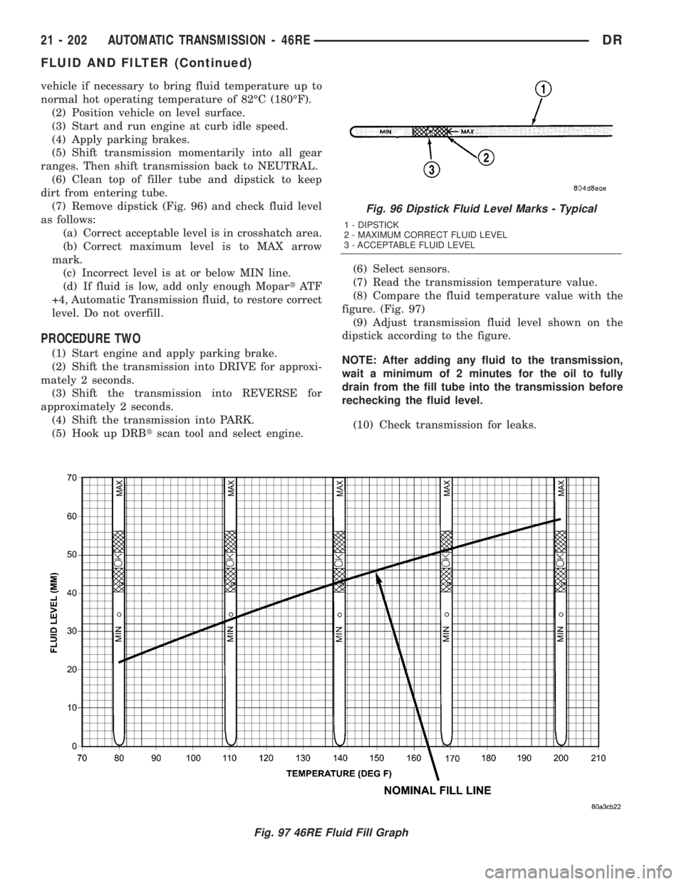
(7) Remove dipstick (Fig. 96) and check fluid level
as follows:
(a) Correct acceptable level is in crosshatch area.
(b) Correct maximum level is to MAX arrow
mark.
(c) Incorrect level is at or below MIN line.
(d) If fluid is low, add only enough MopartAT F
+4, Automatic Transmission fluid, to restore correct
level. Do not overfill.
PROCEDURE TWO
(1) Start engine and apply parking brake.
(2) Shift the transmission into DRIVE for approxi-
mately 2 seconds.
(3) Shift the transmission into REVERSE for
approximately 2 seconds.
(4) Shift the transmission into PARK.
(5) Hook up DRBtscan tool and select engine.(6) Select sensors.
(7) Read the transmission temperature value.
(8) Compare the fluid temperature value with the
figure. (Fig. 97)
(9) Adjust transmission fluid level shown on the
dipstick according to the figure.
NOTE: After adding any fluid to the transmission,
wait a minimum of 2 minutes for the oil to fully
drain from the fill tube into the transmission before
rechecking the fluid level.
(10) Check transmission for leaks.
Fig. 96 Dipstick Fluid Level Marks - Typical
1 - DIPSTICK
2 - MAXIMUM CORRECT FLUID LEVEL
3 - ACCEPTABLE FLUID LEVEL
Fig. 97 46RE Fluid Fill Graph
21 - 202 AUTOMATIC TRANSMISSION - 46REDR
FLUID AND FILTER (Continued)
Page 2221 of 2895

vehicle if necessary to bring fluid temperature up to
normal hot operating temperature of 82ÉC (180ÉF).
(2) Position vehicle on level surface.
(3) Start and run engine at curb idle speed.
(4) Apply parking brakes.
(5) Shift transmission momentarily into all gear
ranges. Then shift transmission back to NEUTRAL.
(6) Clean top of filler tube and dipstick to keep
dirt from entering tube.
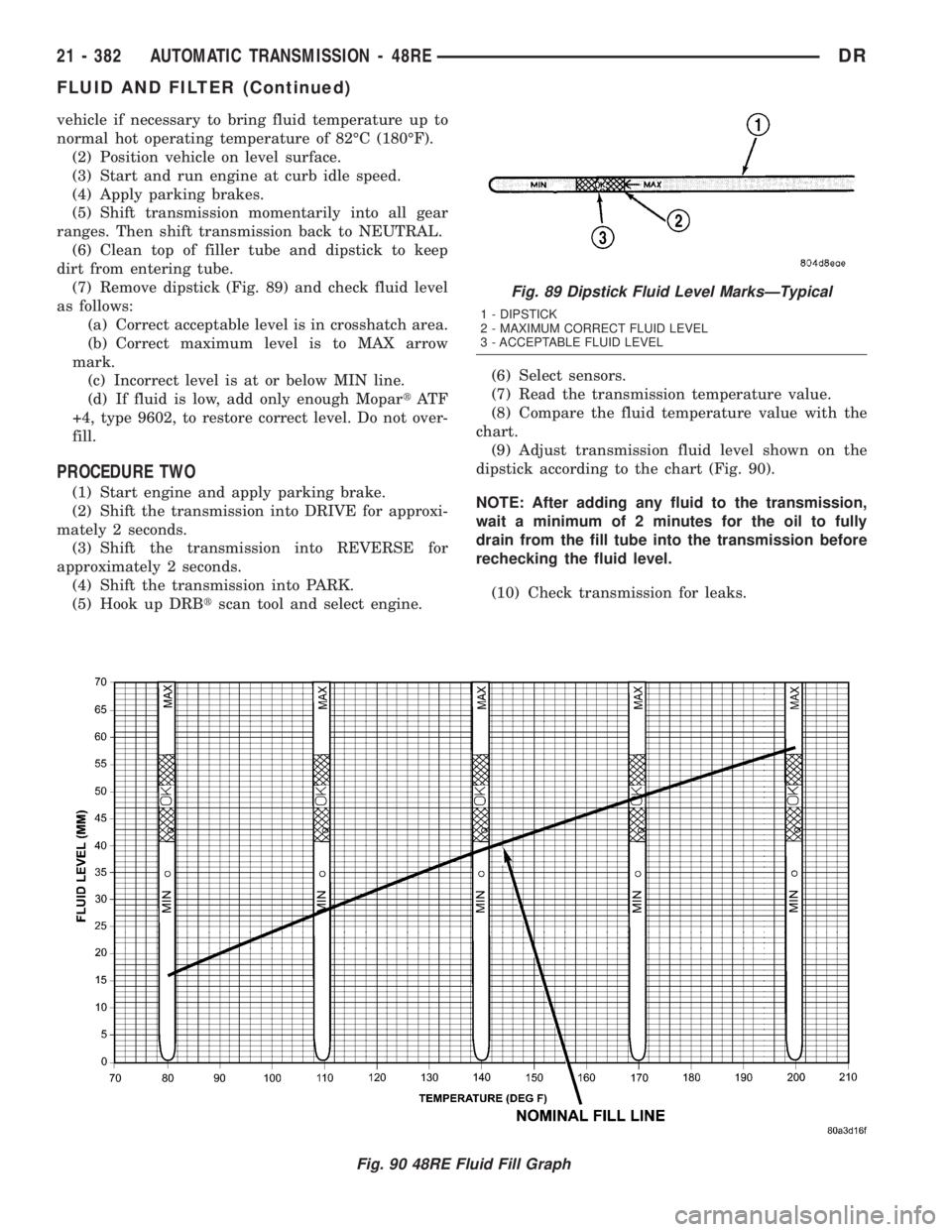
(7) Remove dipstick (Fig. 89) and check fluid level
as follows:
(a) Correct acceptable level is in crosshatch area.
(b) Correct maximum level is to MAX arrow
mark.
(c) Incorrect level is at or below MIN line.
(d) If fluid is low, add only enough MopartAT F
+4, type 9602, to restore correct level. Do not over-
fill.
PROCEDURE TWO
(1) Start engine and apply parking brake.
(2) Shift the transmission into DRIVE for approxi-
mately 2 seconds.
(3) Shift the transmission into REVERSE for
approximately 2 seconds.
(4) Shift the transmission into PARK.
(5) Hook up DRBtscan tool and select engine.(6) Select sensors.
(7) Read the transmission temperature value.
(8) Compare the fluid temperature value with the
chart.
(9) Adjust transmission fluid level shown on the
dipstick according to the chart (Fig. 90).
NOTE: After adding any fluid to the transmission,
wait a minimum of 2 minutes for the oil to fully
drain from the fill tube into the transmission before
rechecking the fluid level.
(10) Check transmission for leaks.
Fig. 90 48RE Fluid Fill Graph
Fig. 89 Dipstick Fluid Level MarksÐTypical
1 - DIPSTICK
2 - MAXIMUM CORRECT FLUID LEVEL
3 - ACCEPTABLE FLUID LEVEL
21 - 382 AUTOMATIC TRANSMISSION - 48REDR
FLUID AND FILTER (Continued)
Page 2381 of 2895

²internal failure that generates debris
²overheat that generates sludge (fluid break-
down)
²failure to replace contaminated converter after
repair
The use of non-recommended fluids can result in
transmission failure. The usual results are erratic
shifts, slippage, abnormal wear and eventual failure
due to fluid breakdown and sludge formation. Avoid
this condition by using recommended fluids only.
The dipstick cap and fill tube should be wiped
clean before checking fluid level. Dirt, grease and
other foreign material on the cap and tube could fall
into the tube if not removed beforehand. Take the
time to wipe the cap and tube clean before withdraw-
ing the dipstick.
Engine coolant in the transmission fluid is gener-
ally caused by a cooler malfunction. The only remedy
is to replace the radiator as the cooler in the radiator
is not a serviceable part. If coolant has circulated
through the transmission, an overhaul is necessary.
The torque converter should be replaced whenever
a failure generates sludge and debris. This is neces-
sary because normal converter flushing procedures
will not remove all contaminants.
STANDARD PROCEDURE
STANDARD PROCEDURE - FLUID LEVEL
CHECK
Low fluid level can cause a variety of conditions
because it allows the pump to take in air along with
the fluid. As in any hydraulic system, air bubbles
make the fluid spongy, therefore, pressures will be
low and build up slowly.
Improper filling can also raise the fluid level too
high. When the transmssion has too much fluid, the
geartrain churns up foam and cause the same condi-
tions which occur with a low fluid level.
In either case, air bubbles can cause overheating
and/or fluid oxidation, and varnishing. This can
interfere with normal valve, clutch, and accumulator
operation. Foaming can also result in fluid escaping
from the transmission vent where it may be mis-
taken for a leak.
After the fluid has been checked, seat the dipstick
fully to seal out water and dirt.
The transmission has a dipstick to check oil level.
It is located on the right side of the engine. Be sure
to wipe all dirt from dipstick handle before removing.
The torque converter fills in both the P (PARK)
and N (NEUTRAL) positions. Place the selector lever
in P (PARK) to be sure that the fluid level check is
accurate.The engine should be running at idle
speed for at least one minute, with the vehicleon level ground.At normal operating temperature
(approximately 82 C. or 180 F.), the fluid level is cor-
rect if it is in the HOT region (cross-hatched area) on
the oil level indicator. The fluid level will be approx-
imately at the upper COLD hole of the dipstick at
70É F fluid temperature.
NOTE: Engine and Transmission should be at nor-
mal operating temperature before performing this
procedure.
(1) Start engine and apply parking brake.
(2) Shift the transmission into DRIVE for approxi-
mately 2 seconds.
(3) Shift the transmission into REVERSE for
approximately 2 seconds.
(4) Shift the transmission into PARK.
(5) Hook up DRBtscan tool and select transmis-
sion.
(6) Select sensors.
(7) Read the transmission temperature value.
(8) Compare the fluid temperature value with the
chart. (Fig. 66)
(9) Adjust transmission fluid level shown on the
dipstick according to the chart.
NOTE: After adding any fluid to the transmission,
wait a minimum of 2 minutes for the oil to fully
drain from the fill tube into the transmission before
rechecking the fluid level.
(10) Check transmission for leaks.
STANDARD PROCEDURE - FLUID AND FILTER
REPLACEMENT
For proper service intervals (Refer to LUBRICA-
TION & MAINTENANCE/MAINTENANCE SCHED-
ULES - DESCRIPTION).
REMOVAL
(1) Hoist and support vehicle on safety stands.
(2) Place a large diameter shallow drain pan
beneath the transmission pan.
(3) Remove bolts holding front and sides of pan to
transmission.
(4) Loosen bolts holding rear of pan to transmis-
sion.
(5) Slowly separate front of pan away from trans-
mission allowing the fluid to drain into drain pan.
(6) Hold up pan and remove remaining bolts hold-
ing pan to transmission.
(7) While holding pan level, lower pan away from
transmission.
(8) Pour remaining fluid in pan into drain pan.
(9) Remove screw holding filter to valve body (Fig.
67).
21 - 542 AUTOMATIC TRANSMISSION - 45RFE/545RFEDR
FLUID AND FILTER (Continued)