2003 DODGE RAM spare tire location
[x] Cancel search: spare tire locationPage 1687 of 2895

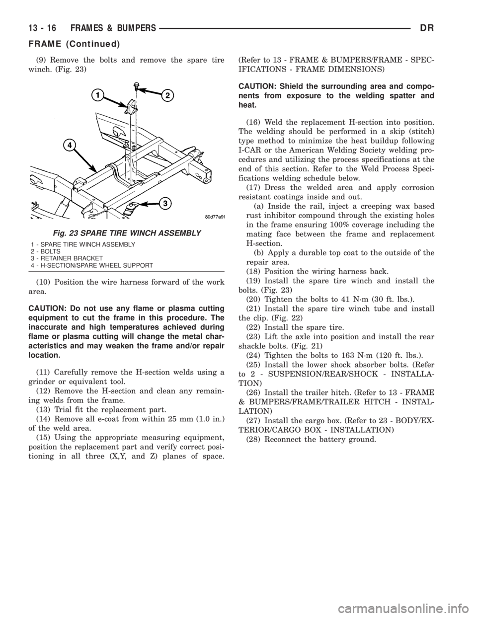
(9) Remove the bolts and remove the spare tire
winch. (Fig. 23)
(10) Position the wire harness forward of the work
area.
CAUTION: Do not use any flame or plasma cutting
equipment to cut the frame in this procedure. The
inaccurate and high temperatures achieved during
flame or plasma cutting will change the metal char-
acteristics and may weaken the frame and/or repair
location.
(11) Carefully remove the H-section welds using a
grinder or equivalent tool.
(12) Remove the H-section and clean any remain-
ing welds from the frame.
(13) Trial fit the replacement part.
(14) Remove all e-coat from within 25 mm (1.0 in.)
of the weld area.
(15) Using the appropriate measuring equipment,
position the replacement part and verify correct posi-
tioning in all three (X,Y, and Z) planes of space.(Refer to 13 - FRAME & BUMPERS/FRAME - SPEC-
IFICATIONS - FRAME DIMENSIONS)
CAUTION: Shield the surrounding area and compo-
nents from exposure to the welding spatter and
heat.
(16) Weld the replacement H-section into position.
The welding should be performed in a skip (stitch)
type method to minimize the heat buildup following
I-CAR or the American Welding Society welding pro-
cedures and utilizing the process specifications at the
end of this section. Refer to the Weld Process Speci-
fications welding schedule below.
(17) Dress the welded area and apply corrosion
resistant coatings inside and out.
(a) Inside the rail, inject a creeping wax based
rust inhibitor compound through the existing holes
in the frame ensuring 100% coverage including the
mating face between the frame and replacement
H-section.
(b) Apply a durable top coat to the outside of the
repair area.
(18) Position the wiring harness back.
(19) Install the spare tire winch and install the
bolts. (Fig. 23)
(20) Tighten the bolts to 41 N´m (30 ft. lbs.).
(21) Install the spare tire winch tube and install
the clip. (Fig. 22)
(22) Install the spare tire.
(23) Lift the axle into position and install the rear
shackle bolts. (Fig. 21)
(24) Tighten the bolts to 163 N´m (120 ft. lbs.).
(25) Install the lower shock absorber bolts. (Refer
to 2 - SUSPENSION/REAR/SHOCK - INSTALLA-
TION)
(26) Install the trailer hitch. (Refer to 13 - FRAME
& BUMPERS/FRAME/TRAILER HITCH - INSTAL-
LATION)
(27) Install the cargo box. (Refer to 23 - BODY/EX-
TERIOR/CARGO BOX - INSTALLATION)
(28) Reconnect the battery ground.
Fig. 23 SPARE TIRE WINCH ASSEMBLY
1 - SPARE TIRE WINCH ASSEMBLY
2 - BOLTS
3 - RETAINER BRACKET
4 - H-SECTION/SPARE WHEEL SUPPORT
13 - 16 FRAMES & BUMPERSDR
FRAME (Continued)
Page 2561 of 2895

METHOD 2 (RELOCATE TIRE ON WHEEL)
NOTE: Rotating the tire on wheel is particularly
effective when there is runout in both tire and
wheel.
(1) Remove tire from wheel and mount wheel on
service dynamic balance machine.
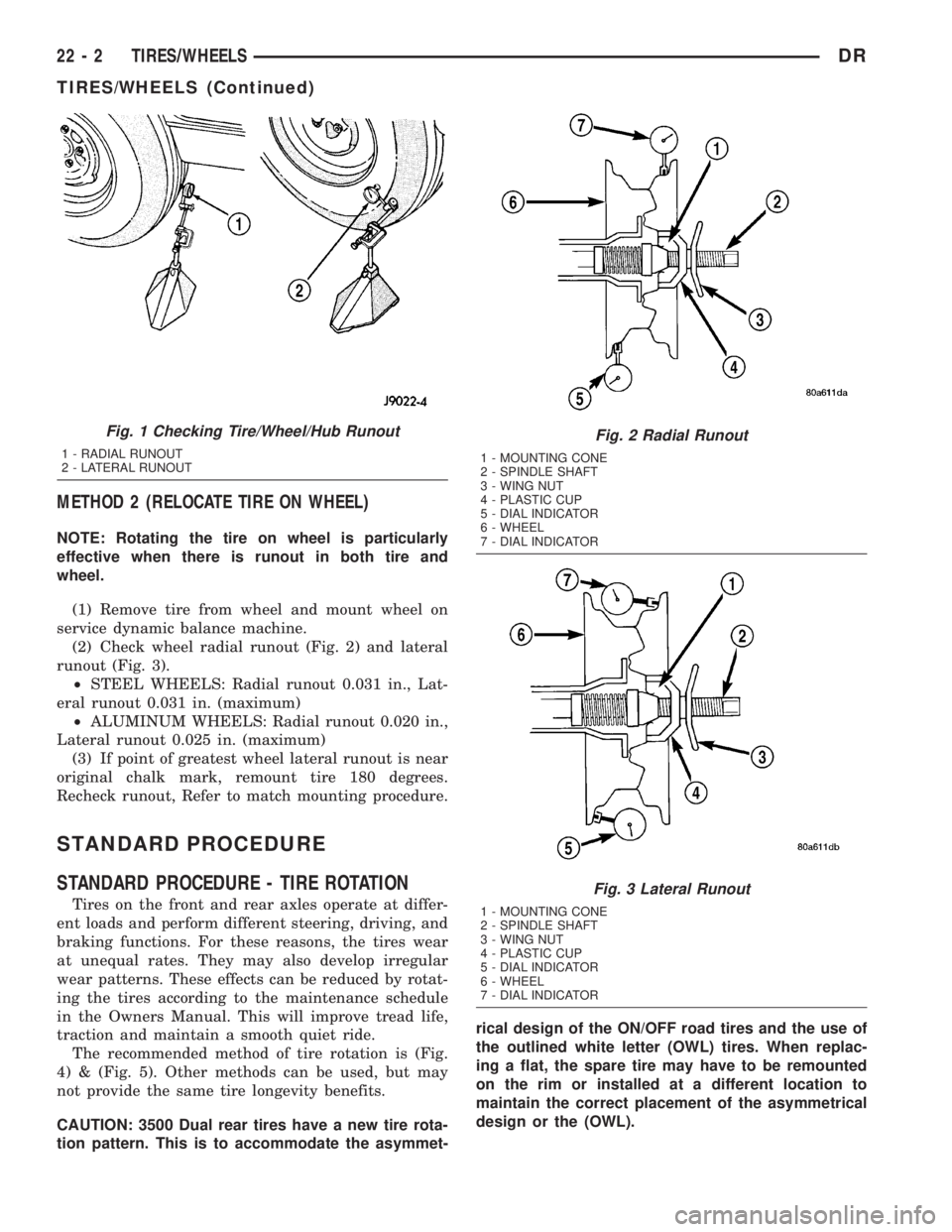
(2) Check wheel radial runout (Fig. 2) and lateral
runout (Fig. 3).
²STEEL WHEELS: Radial runout 0.031 in., Lat-
eral runout 0.031 in. (maximum)
²ALUMINUM WHEELS: Radial runout 0.020 in.,
Lateral runout 0.025 in. (maximum)
(3) If point of greatest wheel lateral runout is near
original chalk mark, remount tire 180 degrees.
Recheck runout, Refer to match mounting procedure.
STANDARD PROCEDURE
STANDARD PROCEDURE - TIRE ROTATION
Tires on the front and rear axles operate at differ-
ent loads and perform different steering, driving, and
braking functions. For these reasons, the tires wear
at unequal rates. They may also develop irregular
wear patterns. These effects can be reduced by rotat-
ing the tires according to the maintenance schedule
in the Owners Manual. This will improve tread life,
traction and maintain a smooth quiet ride.
The recommended method of tire rotation is (Fig.
4) & (Fig. 5). Other methods can be used, but may
not provide the same tire longevity benefits.
CAUTION: 3500 Dual rear tires have a new tire rota-
tion pattern. This is to accommodate the asymmet-rical design of the ON/OFF road tires and the use of
the outlined white letter (OWL) tires. When replac-
ing a flat, the spare tire may have to be remounted
on the rim or installed at a different location to
maintain the correct placement of the asymmetrical
design or the (OWL).
Fig. 1 Checking Tire/Wheel/Hub Runout
1 - RADIAL RUNOUT
2 - LATERAL RUNOUT
Fig. 2 Radial Runout
1 - MOUNTING CONE
2 - SPINDLE SHAFT
3 - WING NUT
4 - PLASTIC CUP
5 - DIAL INDICATOR
6 - WHEEL
7 - DIAL INDICATOR
Fig. 3 Lateral Runout
1 - MOUNTING CONE
2 - SPINDLE SHAFT
3 - WING NUT
4 - PLASTIC CUP
5 - DIAL INDICATOR
6 - WHEEL
7 - DIAL INDICATOR
22 - 2 TIRES/WHEELSDR
TIRES/WHEELS (Continued)
Page 2564 of 2895

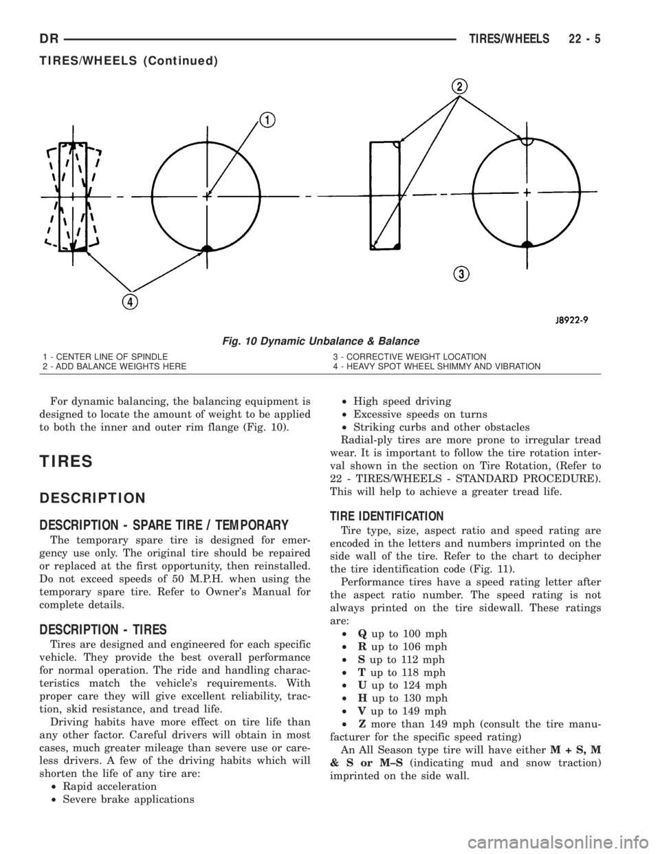
For dynamic balancing, the balancing equipment is
designed to locate the amount of weight to be applied
to both the inner and outer rim flange (Fig. 10).
TIRES
DESCRIPTION
DESCRIPTION - SPARE TIRE / TEMPORARY
The temporary spare tire is designed for emer-
gency use only. The original tire should be repaired
or replaced at the first opportunity, then reinstalled.
Do not exceed speeds of 50 M.P.H. when using the
temporary spare tire. Refer to Owner's Manual for
complete details.
DESCRIPTION - TIRES
Tires are designed and engineered for each specific
vehicle. They provide the best overall performance
for normal operation. The ride and handling charac-
teristics match the vehicle's requirements. With
proper care they will give excellent reliability, trac-
tion, skid resistance, and tread life.
Driving habits have more effect on tire life than
any other factor. Careful drivers will obtain in most
cases, much greater mileage than severe use or care-
less drivers. A few of the driving habits which will
shorten the life of any tire are:
²Rapid acceleration
²Severe brake applications²High speed driving
²Excessive speeds on turns
²Striking curbs and other obstacles
Radial-ply tires are more prone to irregular tread
wear. It is important to follow the tire rotation inter-
val shown in the section on Tire Rotation, (Refer to
22 - TIRES/WHEELS - STANDARD PROCEDURE).
This will help to achieve a greater tread life.
TIRE IDENTIFICATION
Tire type, size, aspect ratio and speed rating are
encoded in the letters and numbers imprinted on the
side wall of the tire. Refer to the chart to decipher
the tire identification code (Fig. 11).
Performance tires have a speed rating letter after
the aspect ratio number. The speed rating is not
always printed on the tire sidewall. These ratings
are:
²Qup to 100 mph
²Rup to 106 mph
²Sup to 112 mph
²Tup to 118 mph
²Uup to 124 mph
²Hup to 130 mph
²Vup to 149 mph
²Zmore than 149 mph (consult the tire manu-
facturer for the specific speed rating)
An All Season type tire will have eitherM+S,M
&SorM±S(indicating mud and snow traction)
imprinted on the side wall.
Fig. 10 Dynamic Unbalance & Balance
1 - CENTER LINE OF SPINDLE
2 - ADD BALANCE WEIGHTS HERE3 - CORRECTIVE WEIGHT LOCATION
4 - HEAVY SPOT WHEEL SHIMMY AND VIBRATION
DRTIRES/WHEELS 22 - 5
TIRES/WHEELS (Continued)
Page 2893 of 2895

VOLUME CHECK - STANDARD
PROCEDURE, OIL PUMP..............21-563
WAIT-TO-START INDICATOR -
DESCRIPTION.......................8J-42
WAIT-TO-START INDICATOR -
OPERATION.........................8J-42
WARNING - INSTALLATION.............23-88
WARNING - REMOVAL................23-88
WARNING - SAFETY PRECAUTIONS AND
WARNINGS..........................23-1
WARNING - SERVICE WARNINGS........24-32
WARNING - WINDSHIELD SAFETY
PRECAUTIONS.......................23-88
WARNING, CLUTCH.....................6-2
WARNINGS, GENERAL..............8W-01-7
WARNINGS, RESTRAINT SYSTEM........8O-5
WARNINGS, WARNING - SAFETY
PRECAUTIONS........................23-1
WARNINGS, WARNING - SERVICE.......24-32
WASHER FLUID INDICATOR -
DESCRIPTION.......................8J-42
WASHER FLUID INDICATOR -
OPERATION.........................8J-42
WASHER FLUID LEVEL SWITCH -
DESCRIPTION........................8R-9
WASHER FLUID LEVEL SWITCH -
INSTALLATION......................8R-11
WASHER FLUID LEVEL SWITCH -
OPERATION..........................8R-9
WASHER FLUID LEVEL SWITCH -
REMOVAL..........................8R-10
WASHER HOSES/TUBES - DESCRIPTION . . 8R-11
WASHER HOSES/TUBES - OPERATION....8R-11
WASHER NOZZLE - DESCRIPTION.......8R-12
WASHER NOZZLE - INSTALLATION......8R-12
WASHER NOZZLE - OPERATION.........8R-12
WASHER NOZZLE - REMOVAL..........8R-12
WASHER PUMP/MOTOR - DESCRIPTION . . 8R-13
WASHER PUMP/MOTOR - INSTALLATION . 8R-14
WASHER PUMP/MOTOR - OPERATION . . . 8R-13
WASHER PUMP/MOTOR - REMOVAL.....8R-14
WASHER RESERVOIR - DESCRIPTION....8R-15
WASHER RESERVOIR - OPERATION......8R-15
WASHER SYSTEM - CLEANING, WIPER....8R-6
WASHER SYSTEM - DIAGNOSIS AND
TESTING, WIPER.....................8R-6
WASHER SYSTEM - INSPECTION, WIPER . . 8R-7
WATER DRAINING AT FUEL FILTER -
STANDARD PROCEDURES..............14-57
WATER IN FUEL SENSOR -
DESCRIPTION.......................14-77
WATER IN FUEL SENSOR - OPERATION . . . 14-78
WATER IN FUEL SENSOR - REMOVAL....14-78
WATER LEAKS - DIAGNOSIS AND
TESTING............................23-1
WATER PUMP - 5.7L - INSTALLATION.....7-71
WATER PUMP - 5.7L - REMOVAL.........7-70
WATER PUMP - 5.9L - CLEANING........7-64
WATER PUMP - 5.9L - DESCRIPTION......7-62
WATER PUMP - 5.9L - INSPECTION.......7-64
WATER PUMP - 5.9L - INSTALLATION.....7-64
WATER PUMP - 5.9L - OPERATION.......7-62
WATER PUMP - 5.9L - REMOVAL.........7-63
WATER PUMP - 5.9L DIESEL -
CLEANING...........................7-67
WATER PUMP - 5.9L DIESEL -
DESCRIPTION........................7-67
WATER PUMP - 5.9L DIESEL -
INSPECTION.........................7-68
WATER PUMP - 5.9L DIESEL -
INSTALLATION........................7-68
WATER PUMP - 5.9L DIESEL -
OPERATION
..........................7-67
WATER PUMP - 5.9L DIESEL - REMOVAL
. . 7-67
WATER PUMP - DESCRIPTION
...........7-64
WATER PUMP - DIAGNOSIS AND
TESTING
........................7-62,7-67
WATER PUMP - OPERATION
.............7-64
WATER PUMP BYPASS - DESCRIPTION
....7-64
WATER PUMP BYPASS - OPERATION
......7-65
WATER PUMP BYPASS HOSE WITH AIR
CONDITIONING - INSTALLATION
..........7-70WATER PUMP BYPASS HOSE WITH AIR
CONDITIONING - REMOVAL.............7-68
WATER PUMP BYPASS HOSE WITHOUT
AIR CONDITIONING - INSTALLATION......7-70
WATER PUMP BYPASS HOSE WITHOUT
AIR CONDITIONING - REMOVAL..........7-69
WATER SEPARATOR - DESCRIPTION,
FUEL FILTER........................14-61
WATER SEPARATOR - INSTALLATION,
FUEL FILTER........................14-62
WATER SEPARATOR - OPERATION, FUEL
FILTER.............................14-61
WATER SEPARATOR - REMOVAL, FUEL
FILTER.............................14-61
WATER TO OIL COOLER - REMOVAL......7-74
WATERDAM - INSTALLATION......23-25,23-34
WATERDAM - REMOVAL..........23-25,23-34
WATER-IN-FUEL INDICATOR -
DESCRIPTION.......................8J-43
WATER-IN-FUEL INDICATOR -
OPERATION.........................8J-43
WEAR - STANDARD PROCEDURE,
MEASURING TIMING CHAIN............9-165
WEAR INDICATORS - DIAGNOSIS AND
TESTING, TREAD......................22-7
WEAR PATTERNS - DIAGNOSIS AND
TESTING, TIRE.......................22-8
WEAR, STANDARD PROCEDURE -
MEASURING TIMING CHAIN.............9-76
WEATHERSTRIP - INSTALLATION, DRIP
RAIL..............................23-91
WEATHERSTRIP - INSTALLATION, FRONT
DOOR GLASS RUN.....................23-92
WEATHERSTRIP - INSTALLATION, REAR
DOOR GLASS RUN...................23-93
WEATHERSTRIP - REMOVAL, DRIP RAIL . . 23-91
WEATHERSTRIP - REMOVAL, FRONT
DOOR GLASS RUN...................23-92
WEATHERSTRIP - REMOVAL, REAR
DOOR GLASS RUN...................23-93
WEATHERSTRIP RETAINER -
INSTALLATION, A-PILLAR..............23-91
WEATHERSTRIP RETAINER -
INSTALLATION, DRIP RAIL.............23-92
WEATHERSTRIP RETAINER - REMOVAL,
A-PILLAR...........................23-91
WEATHERSTRIP RETAINER - REMOVAL,
DRIP RAIL..........................23-92
WELD LOCATIONS - SPECIFICATIONS . . . 23-122
WHEEL - INSTALLATION, STEERING......19-15
WHEEL - REMOVAL, STEERING.........19-15
WHEEL ALIGNMENT - DESCRIPTION.......2-1
WHEEL ALIGNMENT - OPERATION.........2-2
WHEEL ALIGNMENT, SPECIAL TOOLS......2-7
WHEEL ANTILOCK - DIAGNOSIS AND
TESTING, REAR.......................5-42
WHEEL BALANCE - STANDARD
PROCEDURE, TIRE....................22-4
WHEEL COVER - REMOVAL............22-14
WHEEL INSPECTION, DIAGNOSIS AND
TESTING...........................22-11
WHEEL INSTALLATION - STANDARD
PROCEDURE, DUAL REAR.............22-12
WHEEL REPLACEMENT - STANDARD
PROCEDURE........................22-12
WHEEL RUNOUT - DIAGNOSIS AND
TESTING, TIRE.......................22-1
WHEEL SPEED SENSOR - DESCRIPTION,
FRONT..............................5-41
WHEEL SPEED SENSOR - DIAGNOSIS
AND TESTING, REAR...................5-43
WHEEL SPEED SENSOR -
INSTALLATION, FRONT.................5-42
WHEEL SPEED SENSOR -
INSTALLATION, REAR..................5-43
WHEEL SPEED SENSOR - OPERATION,
FRONT..............................5-41
WHEEL SPEED SENSOR - REMOVAL,
FRONT..............................5-41
WHEEL SPEED SENSOR - REMOVAL,
REAR...............................5-42
WHEEL WITH MATCHING TIRE -
DESCRIPTION, FULL SIZE, SPARE.......22-15WHEELHOUSE SPLASH SHIELD -
INSTALLATION, FRONT................23-41
WHEELHOUSE SPLASH SHIELD -
INSTALLATION, REAR.................23-41
WHEELHOUSE SPLASH SHIELD -
REMOVAL, FRONT....................23-40
WHEELHOUSE SPLASH SHIELD -
REMOVAL, REAR.....................23-41
WHEELS - DESCRIPTION..............22-11
WHEELS - OPERATION................22-11
WIND NOISE - DIAGNOSIS AND TESTING . . 23-2
WINDOW MOTOR - REMOVAL..........8N-22
WINDOW REGULATOR - MANUAL -
INSTALLATION..................23-26,23-35
WINDOW REGULATOR - MANUAL -
REMOVAL.....................23-26,23-35
WINDOW REGULATOR - POWER -
INSTALLATION..................23-25,23-34
WINDOW REGULATOR - POWER -
REMOVAL.....................23-25,23-34
WINDOW SWITCH - DIAGNOSIS AND
TESTING...........................8N-22
WINDOW SWITCH - INSTALLATION......8N-23
WINDOW SWITCH - REMOVAL..........8N-23
WINDOWS - DESCRIPTION, POWER.....8N-21
WINDOWS - DIAGNOSIS AND TESTING,
POWER............................8N-21
WINDOWS - OPERATION, POWER.......8N-21
WINDSHIELD SAFETY PRECAUTIONS,
WARNING..........................23-88
WIPER & WASHER SYSTEM - CLEANING....8R-6
WIPER & WASHER SYSTEM -
DIAGNOSIS AND TESTING..............8R-6
WIPER & WASHER SYSTEM -
INSPECTION.........................8R-7
WIPER ARM - DESCRIPTION...........8R-18
WIPER ARM - INSTALLATION...........8R-19
WIPER ARM - OPERATION.............8R-18
WIPER ARM - REMOVAL..............8R-18
WIPER BLADE - DESCRIPTION..........8R-19
WIPER BLADE - INSTALLATION.........8R-20
WIPER BLADE - OPERATION...........8R-19
WIPER BLADE - REMOVAL.............8R-19
WIPER HIGH/LOW RELAY -
DESCRIPTION.......................8R-20
WIPER HIGH/LOW RELAY - DIAGNOSIS
AND TESTING.......................8R-21
WIPER HIGH/LOW RELAY -
INSTALLATION......................8R-21
WIPER HIGH/LOW RELAY - OPERATION . . 8R-20
WIPER HIGH/LOW RELAY - REMOVAL....8R-21
WIPER MODULE - DESCRIPTION........8R-22
WIPER MODULE - INSTALLATION.......8R-23
WIPER MODULE - OPERATION..........8R-23
WIPER MODULE - REMOVAL...........8R-23
WIPER ON/OFF RELAY - DESCRIPTION . . . 8R-25
WIPER ON/OFF RELAY - DIAGNOSIS AND
TESTING...........................8R-26
WIPER ON/OFF RELAY - INSTALLATION . . . 8R-26
WIPER ON/OFF RELAY - OPERATION.....8R-25
WIPER ON/OFF RELAY - REMOVAL......8R-26
WIPERS/WASHERS - DESCRIPTION.......8R-1
WIPERS/WASHERS - OPERATION........8R-4
WIRE SPLICING - STANDARD
PROCEDURE
.....................8W-01-15
WIRING - DESCRIPTION, TRAILER TOW
. . 8L-22
WIRING DIAGRAMS - DESCRIPTION,
HOW TO USE
.....................8W-01-1
WIRING HARNESS - DIAGNOSIS AND
TESTING
.........................8W-01-7
WIRING/TERMINAL, SPECIAL TOOLS
. . 8W-01-10
WITHOUT AIR CONDITIONING -
INSTALLATION, WATER PUMP BYPASS
HOSE
...............................7-70
WITHOUT AIR CONDITIONING -
REMOVAL, WATER PUMP BYPASS
HOSE
...............................7-69
WORN THREADS - STANDARD
PROCEDURE,
REPAIR DAMAGED OR
......9-186,9-232,9-289,
9-361,9-9,9-93
38 INDEXDR
Description Group-Page Description Group-Page Description Group-Page