2003 DODGE RAM TiminG chain guide
[x] Cancel search: TiminG chain guidePage 351 of 2895
water pump while removing pump from vehicle. Do
not remove the clamp from the bypass hose.
(9) Discard the old gasket.
CAUTION: Do not pry the water pump at timing
chain case/cover. The machined surfaces may be
damaged resulting in leaks.
CLEANING
Clean gasket mating surfaces as necessary.
INSPECTION
Visually inspect the water pump and replace if it
has any of the following conditions:
²The body is cracked or damaged
²Water leaks from the shaft seal. This is evident
by traces of coolant below the vent hole
²Loose or rough turning bearing.
²Impeller rubbing the pump body
INSTALLATION
(1) Clean the gasket mating surfaces.
(2) Using a new gasket, install the water pump to
the engine as follows: Guide the water pump tube
into the bypass hose as the pump is being installed.
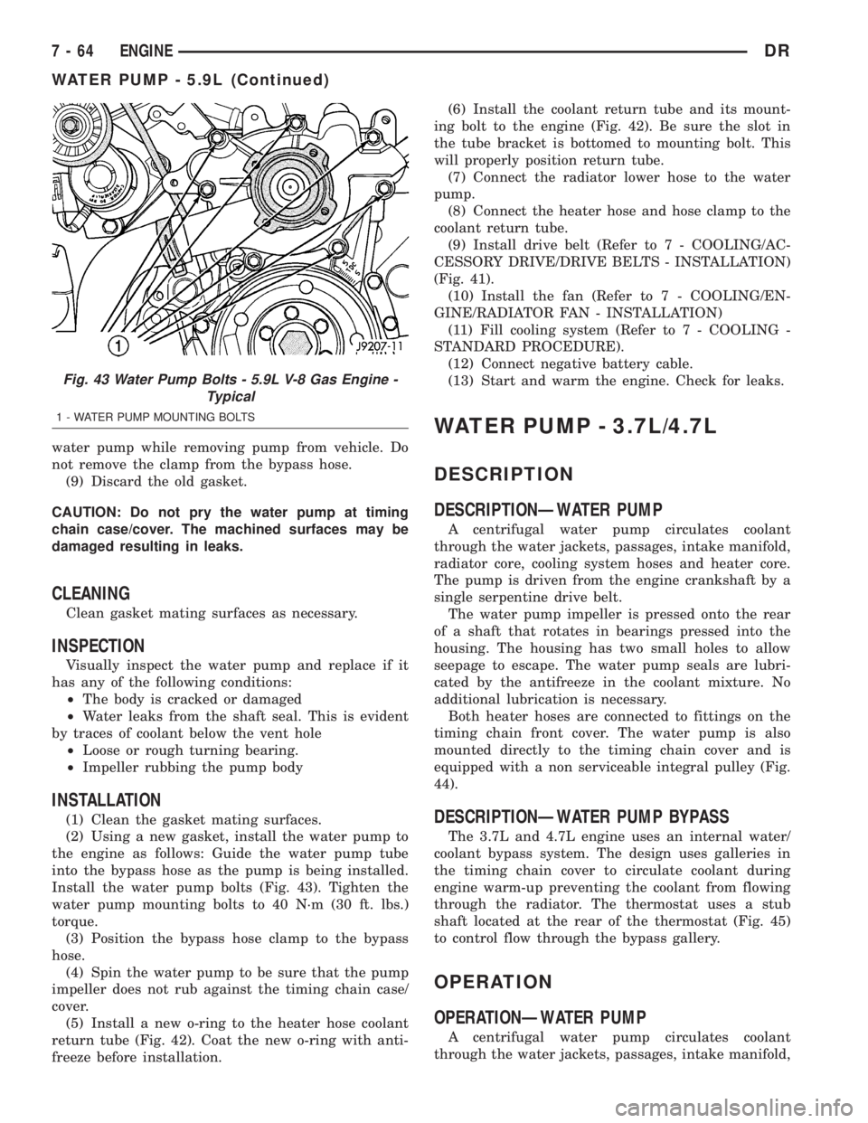
Install the water pump bolts (Fig. 43). Tighten the
water pump mounting bolts to 40 N´m (30 ft. lbs.)
torque.
(3) Position the bypass hose clamp to the bypass
hose.
(4) Spin the water pump to be sure that the pump
impeller does not rub against the timing chain case/
cover.
(5) Install a new o-ring to the heater hose coolant
return tube (Fig. 42). Coat the new o-ring with anti-
freeze before installation.(6) Install the coolant return tube and its mount-
ing bolt to the engine (Fig. 42). Be sure the slot in
the tube bracket is bottomed to mounting bolt. This
will properly position return tube.
(7) Connect the radiator lower hose to the water
pump.
(8) Connect the heater hose and hose clamp to the
coolant return tube.
(9) Install drive belt (Refer to 7 - COOLING/AC-
CESSORY DRIVE/DRIVE BELTS - INSTALLATION)
(Fig. 41).
(10) Install the fan (Refer to 7 - COOLING/EN-
GINE/RADIATOR FAN - INSTALLATION)
(11) Fill cooling system (Refer to 7 - COOLING -
STANDARD PROCEDURE).
(12) Connect negative battery cable.
(13) Start and warm the engine. Check for leaks.
WATER PUMP - 3.7L/4.7L
DESCRIPTION
DESCRIPTIONÐWATER PUMP
A centrifugal water pump circulates coolant
through the water jackets, passages, intake manifold,
radiator core, cooling system hoses and heater core.
The pump is driven from the engine crankshaft by a
single serpentine drive belt.
The water pump impeller is pressed onto the rear
of a shaft that rotates in bearings pressed into the
housing. The housing has two small holes to allow
seepage to escape. The water pump seals are lubri-
cated by the antifreeze in the coolant mixture. No
additional lubrication is necessary.
Both heater hoses are connected to fittings on the
timing chain front cover. The water pump is also
mounted directly to the timing chain cover and is
equipped with a non serviceable integral pulley (Fig.
44).
DESCRIPTIONÐWATER PUMP BYPASS
The 3.7L and 4.7L engine uses an internal water/
coolant bypass system. The design uses galleries in
the timing chain cover to circulate coolant during
engine warm-up preventing the coolant from flowing
through the radiator. The thermostat uses a stub
shaft located at the rear of the thermostat (Fig. 45)
to control flow through the bypass gallery.
OPERATION
OPERATIONÐWATER PUMP
A centrifugal water pump circulates coolant
through the water jackets, passages, intake manifold,
Fig. 43 Water Pump Bolts - 5.9L V-8 Gas Engine -
Typical
1 - WATER PUMP MOUNTING BOLTS
7 - 64 ENGINEDR
WATER PUMP - 5.9L (Continued)
Page 1251 of 2895
ROCKER ARM
DESCRIPTION.........................36
REMOVAL.............................36
VALVE GUIDE SEALS
DESCRIPTION.........................36
VALVE SPRINGS
DESCRIPTION.........................36
REMOVAL.............................37
INSTALLATION.........................37
ENGINE BLOCK
DESCRIPTION.........................37
STANDARD PROCEDUREÐCYLINDER BORE
HONING............................37
CLEANING............................38
INSPECTION..........................38
CRANKSHAFT
DESCRIPTION.........................39
REMOVAL.............................39
INSPECTION..........................40
INSTALLATION.........................41
CRANKSHAFT MAIN BEARINGS
STANDARD PROCEDURE
MAIN BEARING FITTING................43
CRANKSHAFT OIL SEAL - FRONT
REMOVAL.............................44
INSTALLATION.........................45
CRANKSHAFT OIL SEAL - REAR
REMOVAL.............................45
INSTALLATION.........................46
FLEX PLATE
REMOVAL.............................47
INSTALLATION.........................47
PISTON & CONNECTING ROD
DESCRIPTION.........................47
STANDARD PROCEDURE
CONNECTING ROD BEARING FITTING....48
STANDARD PROCEDUREÐPISTON
FITTING.............................50
REMOVAL.............................50
CLEANING............................51
INSPECTION..........................51
INSTALLATION.........................51
PISTON RINGS
STANDARD PROCEDURE - PISTON RING
FITTING.............................52
VIBRATION DAMPER
REMOVAL.............................54
INSTALLATION.........................55
STRUCTURAL COVER
DESCRIPTION.........................56
OPERATION...........................56
REMOVAL.............................56
INSTALLATION.........................56
FRONT MOUNT
REMOVAL.............................57
INSTALLATION.........................58REAR MOUNT
REMOVAL.............................60
INSTALLATION.........................60
LUBRICATION
DESCRIPTION.........................60
OPERATION...........................60
DIAGNOSIS AND TESTING
DIAGNOSIS AND TESTINGÐENGINE OIL
LEAK...............................63
DIAGNOSIS AND TESTING - CHECKING
ENGINE OIL PRESSURE................64
DIAGNOSIS AND TESTING - REAR SEAL
AREA LEAKS.........................64
OIL PAN
DESCRIPTION.........................65
REMOVAL.............................65
CLEANING............................65
INSPECTION..........................66
INSTALLATION.........................66
OIL PRESSURE SENSOR/SWITCH
DESCRIPTION.........................66
OPERATION...........................66
REMOVAL.............................67
INSTALLATION.........................67
OIL PUMP
REMOVAL.............................67
DISASSEMBLY.........................67
INSPECTION..........................67
ASSEMBLY............................68
INSTALLATION.........................68
OIL FILTER
REMOVAL.............................69
INSTALLATION.........................70
OIL
STANDARD PROCEDURE - ENGINE OIL
SERVICE............................70
INTAKE MANIFOLD
DESCRIPTION.........................71
DIAGNOSIS AND TESTING - INTAKE
MANIFOLD LEAKS.....................71
REMOVAL.............................72
INSTALLATION.........................72
EXHAUST MANIFOLD
DESCRIPTION.........................73
REMOVAL.............................73
INSTALLATION.........................74
VALVE TIMING
DESCRIPTION.........................75
OPERATION...........................75
STANDARD PROCEDURE
MEASURING TIMING CHAIN WEAR.......76
SERVICE PROCEDURE - TIMING
VERIFICATION........................76
BALANCE SHAFT
REMOVAL.............................79
INSTALLATION.........................79
9 - 2 ENGINE - 3.7LDR
Page 1264 of 2895
DESCRIPTION SPECIFICATION
Cover Out - of -Flat
(MAX)0.025 mm (0.001 in.)
Inner and Outer Rotor
Thickness 12.02 mm (0.4731 in.)
Outer Rotor to pocket
(Diametral) clearance
(MAX).235 mm (.0093 in.)
Outer Rotor Diameter
(MIN)85.925 mm (0.400 in.)
Tip Clearance Between
Rotors
(MAX) 0.150 mm (0.006 in.)
OIL PRESSURE
At Curb Idle Speed
(MIN)*25 kPa (4 psi)
@ 3000 rpm 170 - 758 kPa (25 - 110
psi)
* CAUTION: If pressure is zero at curb idle, DO
NOT run engine at 3000 rpm.
TORQUE
DESCRIPTION N´m Ft. In.
Lbs. Lbs.
Camshaft
Non - Oiled Sprocket Bolt 122 90 Ð
Bearing Cap Bolts 11 Ð 100
Counterbalance shaft
retaining bolt28 Ð 250
Timing Chain CoverÐBolts 58 43 Ð
Connecting Rod CapÐBolts 27 20 Ð
PLUS 90É TURN
Bed PlateÐBolts Refer to Procedure
Crankshaft DamperÐBolt 175 130 Ð
Cylinder HeadÐBolts
M11 Bolts Refer ToProcedure
M8 Bolts - - -
Cylinder Head CoverÐBolts 12 Ð 105
Exhaust ManifoldÐBolts 25 18 Ð
Exhaust Manifold Heat
ShieldÐNuts8Ð72
Then loosen 45É
DESCRIPTION N´m Ft. In.
Lbs. Lbs.
FlexplateÐBolts 95 70 Ð
Engine Mount Bracket to
BlockÐBolts61 45 Ð
Rear Mount to
TransmissionÐBolts46 34 Ð
Generator MountingÐBolts
M10 Bolts 54 40 Ð
M8 Bolts 28 Ð 250
Intake ManifoldÐBolts 12 Ð 105
Refer to Procedure
for
Tightening Sequence
Oil PanÐBolts 15 Ð 130
Oil PanÐDrain Plug 34 25 Ð
Oil PumpÐBolts 28 Ð 250
Oil Pump CoverÐBolts 12 Ð 105
Oil Pickup TubeÐBolt and
Nut28 Ð 250
Oil Dipstick Tube to Engine
BlockÐBolt 15 Ð 130
Oil Fill TubeÐBolts 12 Ð 105
Timing Chain GuideÐBolts 28 Ð 250
Timing Chain Tensioner Arm 28 Ð 250
Hydraulic TensionerÐBolts 28 Ð 250
Timing Chain Primary
TensionerÐBolts28 Ð 250
Timing Drive Idler SprocketÐ
Bolt34 25 Ð
Thermostat HousingÐBolts 12 Ð 105
Water PumpÐBolts 58 43 Ð
DRENGINE - 3.7L 9 - 15
ENGINE - 3.7L (Continued)
Page 1271 of 2895
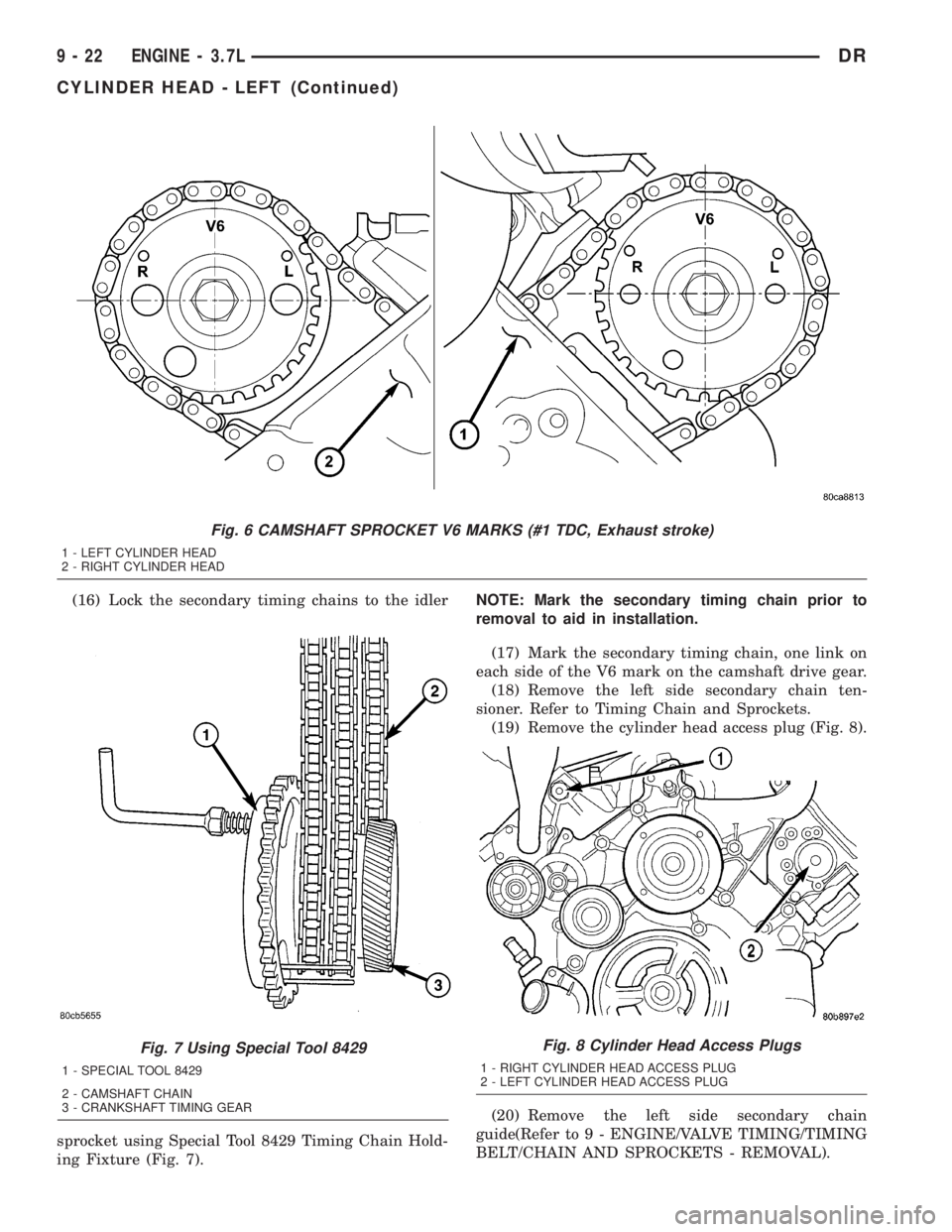
(16) Lock the secondary timing chains to the idler
sprocket using Special Tool 8429 Timing Chain Hold-
ing Fixture (Fig. 7).NOTE: Mark the secondary timing chain prior to
removal to aid in installation.
(17) Mark the secondary timing chain, one link on
each side of the V6 mark on the camshaft drive gear.
(18) Remove the left side secondary chain ten-
sioner. Refer to Timing Chain and Sprockets.
(19) Remove the cylinder head access plug (Fig. 8).
(20) Remove the left side secondary chain
guide(Refer to 9 - ENGINE/VALVE TIMING/TIMING
BELT/CHAIN AND SPROCKETS - REMOVAL).
Fig. 7 Using Special Tool 8429
1 - SPECIAL TOOL 8429
2 - CAMSHAFT CHAIN
3 - CRANKSHAFT TIMING GEAR
Fig. 6 CAMSHAFT SPROCKET V6 MARKS (#1 TDC, Exhaust stroke)
1 - LEFT CYLINDER HEAD
2 - RIGHT CYLINDER HEAD
Fig. 8 Cylinder Head Access Plugs
1 - RIGHT CYLINDER HEAD ACCESS PLUG
2 - LEFT CYLINDER HEAD ACCESS PLUG
9 - 22 ENGINE - 3.7LDR
CYLINDER HEAD - LEFT (Continued)
Page 1273 of 2895
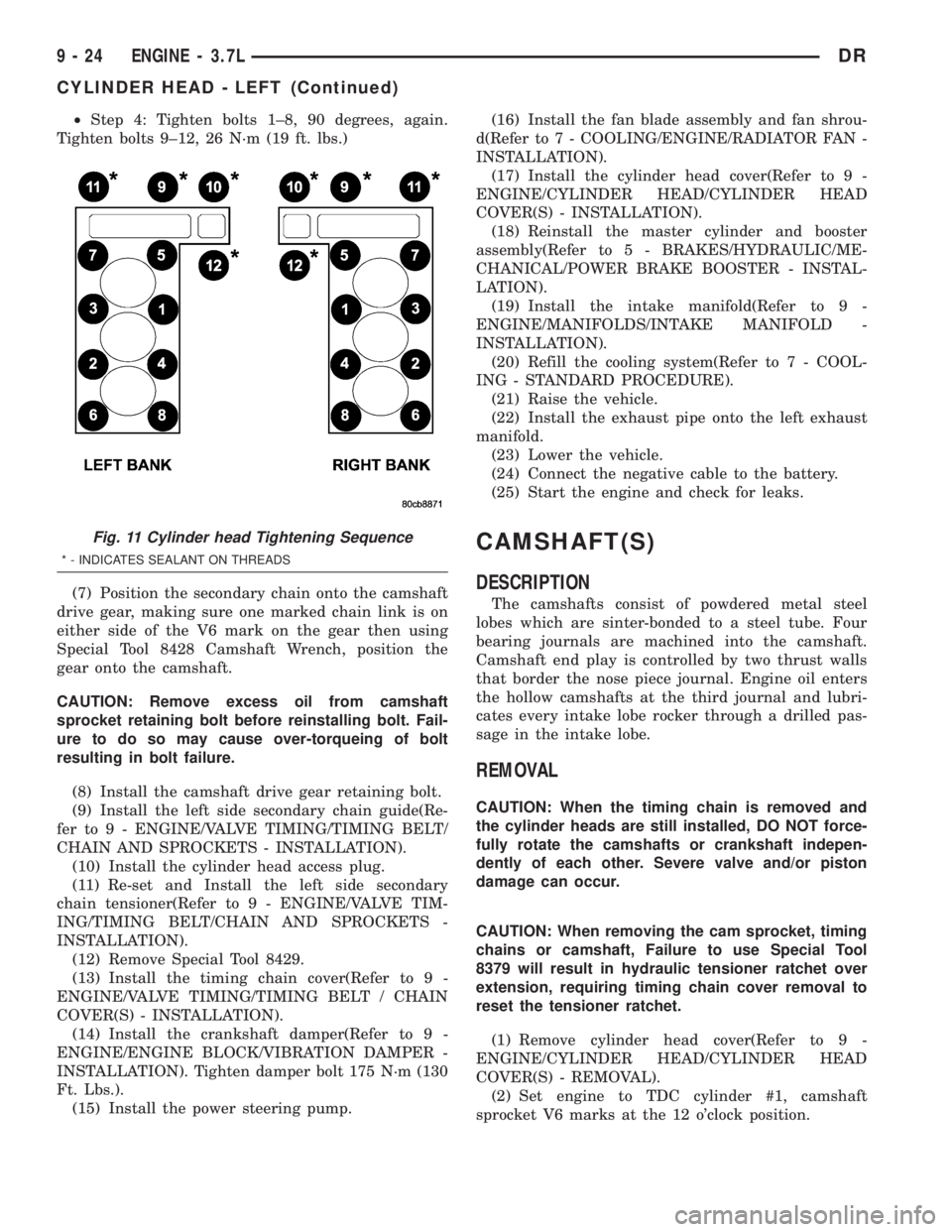
²Step 4: Tighten bolts 1±8, 90 degrees, again.
Tighten bolts 9±12, 26 N´m (19 ft. lbs.)
(7) Position the secondary chain onto the camshaft
drive gear, making sure one marked chain link is on
either side of the V6 mark on the gear then using
Special Tool 8428 Camshaft Wrench, position the
gear onto the camshaft.
CAUTION: Remove excess oil from camshaft
sprocket retaining bolt before reinstalling bolt. Fail-
ure to do so may cause over-torqueing of bolt
resulting in bolt failure.
(8) Install the camshaft drive gear retaining bolt.
(9) Install the left side secondary chain guide(Re-
fer to 9 - ENGINE/VALVE TIMING/TIMING BELT/
CHAIN AND SPROCKETS - INSTALLATION).
(10) Install the cylinder head access plug.
(11) Re-set and Install the left side secondary
chain tensioner(Refer to 9 - ENGINE/VALVE TIM-
ING/TIMING BELT/CHAIN AND SPROCKETS -
INSTALLATION).
(12) Remove Special Tool 8429.
(13) Install the timing chain cover(Refer to 9 -
ENGINE/VALVE TIMING/TIMING BELT / CHAIN
COVER(S) - INSTALLATION).
(14) Install the crankshaft damper(Refer to 9 -
ENGINE/ENGINE BLOCK/VIBRATION DAMPER -
INSTALLATION). Tighten damper bolt 175 N´m (130
Ft. Lbs.).
(15) Install the power steering pump.(16) Install the fan blade assembly and fan shrou-
d(Refer to 7 - COOLING/ENGINE/RADIATOR FAN -
INSTALLATION).
(17) Install the cylinder head cover(Refer to 9 -
ENGINE/CYLINDER HEAD/CYLINDER HEAD
COVER(S) - INSTALLATION).
(18) Reinstall the master cylinder and booster
assembly(Refer to 5 - BRAKES/HYDRAULIC/ME-
CHANICAL/POWER BRAKE BOOSTER - INSTAL-
LATION).
(19) Install the intake manifold(Refer to 9 -
ENGINE/MANIFOLDS/INTAKE MANIFOLD -
INSTALLATION).
(20) Refill the cooling system(Refer to 7 - COOL-
ING - STANDARD PROCEDURE).
(21) Raise the vehicle.
(22) Install the exhaust pipe onto the left exhaust
manifold.
(23) Lower the vehicle.
(24) Connect the negative cable to the battery.
(25) Start the engine and check for leaks.
CAMSHAFT(S)
DESCRIPTION
The camshafts consist of powdered metal steel
lobes which are sinter-bonded to a steel tube. Four
bearing journals are machined into the camshaft.
Camshaft end play is controlled by two thrust walls
that border the nose piece journal. Engine oil enters
the hollow camshafts at the third journal and lubri-
cates every intake lobe rocker through a drilled pas-
sage in the intake lobe.
REMOVAL
CAUTION: When the timing chain is removed and
the cylinder heads are still installed, DO NOT force-
fully rotate the camshafts or crankshaft indepen-
dently of each other. Severe valve and/or piston
damage can occur.
CAUTION: When removing the cam sprocket, timing
chains or camshaft, Failure to use Special Tool
8379 will result in hydraulic tensioner ratchet over
extension, requiring timing chain cover removal to
reset the tensioner ratchet.
(1) Remove cylinder head cover(Refer to 9 -
ENGINE/CYLINDER HEAD/CYLINDER HEAD
COVER(S) - REMOVAL).
(2) Set engine to TDC cylinder #1, camshaft
sprocket V6 marks at the 12 o'clock position.
Fig. 11 Cylinder head Tightening Sequence
* - INDICATES SEALANT ON THREADS
9 - 24 ENGINE - 3.7LDR
CYLINDER HEAD - LEFT (Continued)
Page 1274 of 2895

(3) Mark one link on the secondary timing chain
on both sides of the V6 mark on the camshaft
sprocket to aid in installation.
CAUTION: Do not hold or pry on the camshaft tar-
get wheel (Located on the right side camshaft
sprocket) for any reason, Severe damage will occur
to the target wheel resulting in a vehicle no start
condition.
(4) Loosen butDO NOTremove the camshaft
sprocket retaining bolt. Leave the bolt snug against
the sprocket.
NOTE: The timing chain tensioners must be
secured prior to removing the camshaft sprockets.
Failure to secure tensioners will allow the tension-
ers to extend, requiring timing chain cover removal
in order to reset tensioners.
CAUTION: Do not force wedge past the narrowest
point between the chain strands. Damage to the
tensioners may occur.
(5) Position Special Tool 8379 timing chain wedge
between the timing chain strands, tap the tool to
securely wedge the timing chain against the ten-
sioner arm and guide (Fig. 12).
(6) Hold the camshaft with Special Tool 8428 Cam-
shaft Wrench, while removing the camshaft sprocket
bolt and sprocket (Fig. 13).(7) Using Special Tool 8428 Camshaft Wrench,
gently allow the camshaft to rotate 5É clockwise until
the camshaft is in the neutral position (no valve
load).
(8) Starting at the outside working inward, loosen
the camshaft bearing cap retaining bolts 1/2 turn at
a time. Repeat until all load is off the bearing caps.
CAUTION: DO NOT STAMP OR STRIKE THE CAM-
SHAFT BEARING CAPS. SEVERE DAMAGE WILL
OCCUR TO THE BEARING CAPS.
NOTE: When the camshaft is removed the rocker
arms may slide downward, mark the rocker arms
before removing camshaft.
(9) Remove the camshaft bearing caps and the
camshaft.
INSTALLATION
(1) Lubricate camshaft journals with clean engine
oil.
NOTE: Position the left side camshaft so that the
camshaft sprocket dowel is near the 1 o'clock posi-
tion, This will place the camshaft at the neutral
position easing the installation of the camshaft
bearing caps.
(2) Position the camshaft into the cylinder head.
Fig. 12 SECURING TIMING CHAIN TENSIONERS
USING TIMING CHAIN WEDGE Ð Typical
1 - SPECIAL TOOL 8379
2 - CAMSHAFT SPROCKET
3 - CAMSHAFT SPROCKET BOLT
4 - CYLINDER HEAD
Fig. 13 Special Tool 8428
1 - Camshaft hole
2 - Special Tool 8428
DRENGINE - 3.7L 9 - 25
CAMSHAFT(S) (Continued)
Page 1281 of 2895
(6) Air ingested into oil due to broken or cracked
oil pump pick up.
(7) Worn valve guides.
(8) Rocker arm ears contacting valve spring
retainer.
(9) Rocker arm loose, adjuster stuck or at maxi-
mum extension and still leaves lash in the system.
(10) Oil leak or excessive cam bore wear in cylin-
der head.
(11) Faulty lash adjuster.
a. Check lash adjusters for sponginess while
installed in cylinder head and cam on camshaft at
base circle. Depress part of rocker arm over adjuster.
Normal adjusters should feel very firm. Spongy
adjusters can be bottomed out easily.
b. Remove suspected lash adjusters, and replace.
c. Before installation, make sure adjusters are at
least partially full of oil. This can be verified by little
or no plunger travel when lash adjuster is depressed.
REMOVAL
(1) Disconnect battery negative cable.
(2) Raise the vehicle on a hoist.
(3) Disconnect the exhaust pipe at the right side
exhaust manifold.
(4) Drain the engine coolant(Refer to 7 - COOL-
ING - STANDARD PROCEDURE).
(5) Lower the vehicle.
(6) Remove the intake manifold(Refer to 9 -
ENGINE/MANIFOLDS/INTAKE MANIFOLD -
REMOVAL).
(7) Remove the cylinder head cover(Refer to 9 -
ENGINE/CYLINDER HEAD - REMOVAL).
(8) Remove the fan shroud(Refer to 7 - COOLING/
ENGINE/RADIATOR FAN - REMOVAL).
(9) Remove oil fill housing from cylinder head.
(10) Remove accessory drive belt(Refer to 7 -
COOLING/ACCESSORY DRIVE/DRIVE BELTS -
REMOVAL).
(11) Rotate the crankshaft until the damper timing
mark is aligned with TDC indicator mark.
(12) Verify the V6 mark on the camshaft sprocket
is at the 12 o'clock position. Rotate the crankshaft
one turn if necessary.
(13) Remove the crankshaft damper(Refer to 9 -
ENGINE/ENGINE BLOCK/VIBRATION DAMPER -
REMOVAL).
(14) Remove the timing chain cover(Refer to 9 -
ENGINE/VALVE TIMING/TIMING BELT / CHAIN
COVER(S) - REMOVAL).
(15) Lock the secondary timing chains to the idler
sprocket using Special Tool 8429 Timing Chain Hold-
ing Fixture.
NOTE: Mark the secondary timing chain prior to
removal to aid in installation.(16) Mark the secondary timing chain, one link on
each side of the V6 mark on the camshaft drive gear.
(17) Remove the right side secondary chain ten-
sioner(Refer to 9 - ENGINE/VALVE TIMING/TIM-
ING BELT/CHAIN AND SPROCKETS - REMOVAL).
(18) Remove the cylinder head access plug.
(19) Remove the right side secondary chain
guide(Refer to 9 - ENGINE/VALVE TIMING/TIMING
BELT/CHAIN AND SPROCKETS - REMOVAL).
CAUTION: The nut on the right side camshaft
sprocket should not be removed for any reason, as
the sprocket and camshaft sensor target wheel is
serviced as an assembly. If the nut was removed
retorque nut to 5 N´m (44 in. lbs.).
(20) Remove the retaining bolt and the camshaft
drive gear.
CAUTION: Do not allow the engine to rotate. severe
damage to the valve train can occur.
CAUTION: Do not overlook the four smaller bolts at
the front of the cylinder head. Do not attempt to
remove the cylinder head without removing these
four bolts.
CAUTION: Do not hold or pry on the camshaft tar-
get wheel for any reason. A damaged target wheel
can result in a vehicle no start condition.
NOTE: The cylinder head is attached to the cylinder
block with twelve bolts.
(21) Remove the cylinder head retaining bolts.
(22) Remove the cylinder head and gasket. Discard
the gasket.
CAUTION: Do not lay the cylinder head on its gas-
ket sealing surface, do to the design of the cylinder
head gasket any distortion to the cylinder head
sealing surface may prevent the gasket from prop-
erly sealing resulting in leaks.
INSTALLATION
NOTE: The cylinder head bolts are tightened using
a torque plus angle procedure. The bolts must be
examined BEFORE reuse. If the threads are necked
down the bolts should be replaced.
Necking can be checked by holding a straight edge
against the threads (Fig. 24). If all the threads do not
contact the scale, the bolt should be replaced.
9 - 32 ENGINE - 3.7LDR
CYLINDER HEAD - RIGHT (Continued)
Page 1283 of 2895
(7) Position the secondary chain onto the camshaft
drive gear, making sure one marked chain link is on
either side of the V6 mark on the gear then using
Special Tool 8428 Camshaft Wrench, position the
gear onto the camshaft.
CAUTION: Remove excess oil from camshaft
sprocket retaining bolt before reinstalling bolt. Fail-
ure to do so may cause over-torquing of bolt result-
ing in bolt failure.
(8) Install the camshaft drive gear retaining bolt.
(9) Install the right side secondary chain guide(Re-
fer to 9 - ENGINE/VALVE TIMING/TIMING BELT/
CHAIN AND SPROCKETS - INSTALLATION).
(10) Install the cylinder head access plug.
(11) Re-set and install the right side secondary
chain tensioner(Refer to 9 - ENGINE/VALVE TIM-
ING/TIMING BELT/CHAIN AND SPROCKETS -
INSTALLATION).
(12) Remove Special Tool 8429.
(13) Install the timing chain cover(Refer to 9 -
ENGINE/VALVE TIMING/TIMING BELT / CHAIN
COVER(S) - REMOVAL).
(14) Install the crankshaft damper(Refer to 9 -
ENGINE/ENGINE BLOCK/VIBRATION DAMPER -
INSTALLATION). Tighten damper bolt 175 N´m (130
Ft. Lbs.).
(15) Install accessory drive belt(Refer to 7 - COOL-
ING/ACCESSORY DRIVE/DRIVE BELTS - INSTAL-
LATION).
(16) Install the fan shroud(Refer to 7 - COOLING/
ENGINE/RADIATOR FAN - INSTALLATION).
(17) Install the cylinder head cover(Refer to 9 -
ENGINE/CYLINDER HEAD/CYLINDER HEAD
COVER(S) - INSTALLATION).
(18) Install the intake manifold(Refer to 9 -
ENGINE/MANIFOLDS/INTAKE MANIFOLD -
INSTALLATION).
(19) Install oil fill housing onto cylinder head.
(20) Refill the cooling system(Refer to 7 - COOL-
ING - STANDARD PROCEDURE).
(21) Raise the vehicle.
(22) Install the exhaust pipe onto the right
exhaust manifold.
(23) Lower the vehicle.
(24) Reconnect battery negative cable.
(25) Start the engine and check for leaks.
CAMSHAFT(S)
DESCRIPTION
The camshafts consist of powdered metal steel
lobes which are sinter-bonded to a steel tube. Four
bearing journals are machined into the camshaft.
Camshaft end play is controlled by two thrust wallsthat border the nose piece journal. Engine oil enters
the hollow camshafts at the third journal and lubri-
cates every intake lobe rocker through a drilled pas-
sage in the intake lobe.
REMOVAL
CAUTION: When the timing chain is removed and
the cylinder heads are still installed, DO NOT force-
fully rotate the camshafts or crankshaft indepen-
dently of each other. Severe valve and/or piston
damage can occur.
CAUTION: When removing the cam sprocket, timing
chains or camshaft, Failure to use special tool 8379
will result in hydraulic tensioner ratchet over exten-
sion, Requiring timing chain cover removal to re-set
the tensioner ratchet.
(1) Remove the cylinder head cover(Refer to 9 -
ENGINE/CYLINDER HEAD/CYLINDER HEAD
COVER(S) - REMOVAL).
(2) Set engine to TDC cylinder #1, camshaft
sprocket V6 marks at the 12 o'clock position.
(3) Mark one link on the secondary timing chain
on both sides of the V6 mark on the camshaft
sprocket to aid in installation.
CAUTION: Do not hold or pry on the camshaft tar-
get wheel for any reason, Severe damage will occur
to the target wheel. A damaged target wheel could
cause a vehicle no start condition.
(4) Loosen butDO NOTremove the camshaft
sprocket retaining bolt. Leave bolt snug against
sprocket.
NOTE: The timing chain tensioners must be
secured prior to removing the camshaft sprockets.
Failure to secure tensioners will allow the tension-
ers to extend, requiring timing chain cover removal
in order to reset tensioners.
CAUTION: Do not force wedge past the narrowest
point between the chain strands. Damage to the
tensioners may occur.
(5) Position Special Tool 8379 timing chain wedge
between the timing chain strands. Tap the tool to
securely wedge the timing chain against the ten-
sioner arm and guide.
(6) Remove the camshaft position sensor.
(7) Hold the camshaft with Special Tool 8428 Cam-
shaft Wrench, while removing the camshaft sprocket
bolt and sprocket.
9 - 34 ENGINE - 3.7LDR
CYLINDER HEAD - RIGHT (Continued)