2003 DODGE RAM Removing door panel
[x] Cancel search: Removing door panelPage 637 of 2895
before removing the airbag from the vehicle. (Refer to
8 - ELECTRICAL/RESTRAINTS - STANDARD PRO-
CEDURE - SERVICE AFTER A SUPPLEMENTAL
RESTRAINT DEPLOYMENT).
WARNING: ON VEHICLES EQUIPPED WITH AIR-
BAGS, DISABLE THE SUPPLEMENTAL RESTRAINT
SYSTEM BEFORE ATTEMPTING ANY STEERING
WHEEL, STEERING COLUMN, DRIVER AIRBAG,
PASSENGER AIRBAG, SEAT BELT TENSIONER,
SIDE CURTAIN AIRBAG, OR INSTRUMENT PANEL
COMPONENT DIAGNOSIS OR SERVICE. DISCON-
NECT AND ISOLATE THE BATTERY NEGATIVE
(GROUND) CABLE, THEN WAIT TWO MINUTES FOR
THE SYSTEM CAPACITOR TO DISCHARGE BEFORE
PERFORMING FURTHER DIAGNOSIS OR SERVICE.
THIS IS THE ONLY SURE WAY TO DISABLE THE
SUPPLEMENTAL RESTRAINT SYSTEM. FAILURE TO
TAKE THE PROPER PRECAUTIONS COULD
RESULT IN ACCIDENTAL AIRBAG DEPLOYMENT
AND POSSIBLE PERSONAL INJURY.
WARNING: WHEN REMOVING A DEPLOYED AIR-
BAG, RUBBER GLOVES, EYE PROTECTION, AND A
LONG-SLEEVED SHIRT SHOULD BE WORN. THERE
MAY BE DEPOSITS ON THE AIRBAG UNIT AND
OTHER INTERIOR SURFACES. IN LARGE DOSES,
THESE DEPOSITS MAY CAUSE IRRITATION TO THE
SKIN AND EYES.
(1) Disconnect and isolate the battery negative
cable. Wait two minutes for the system capacitor to
discharge before further service.
(2) Remove the lower surround from the instru-
ment panel. (Refer to 23 - BODY/INSTRUMENT
PANEL/LOWER SURROUND - REMOVAL).
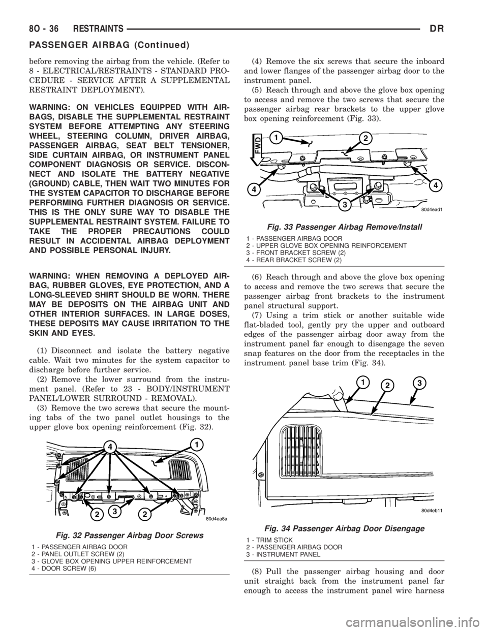
(3) Remove the two screws that secure the mount-
ing tabs of the two panel outlet housings to the
upper glove box opening reinforcement (Fig. 32).(4) Remove the six screws that secure the inboard
and lower flanges of the passenger airbag door to the
instrument panel.
(5) Reach through and above the glove box opening
to access and remove the two screws that secure the
passenger airbag rear brackets to the upper glove
box opening reinforcement (Fig. 33).
(6) Reach through and above the glove box opening
to access and remove the two screws that secure the
passenger airbag front brackets to the instrument
panel structural support.
(7) Using a trim stick or another suitable wide
flat-bladed tool, gently pry the upper and outboard
edges of the passenger airbag door away from the
instrument panel far enough to disengage the seven
snap features on the door from the receptacles in the
instrument panel base trim (Fig. 34).
(8) Pull the passenger airbag housing and door
unit straight back from the instrument panel far
enough to access the instrument panel wire harness
Fig. 32 Passenger Airbag Door Screws
1 - PASSENGER AIRBAG DOOR
2 - PANEL OUTLET SCREW (2)
3 - GLOVE BOX OPENING UPPER REINFORCEMENT
4 - DOOR SCREW (6)
Fig. 33 Passenger Airbag Remove/Install
1 - PASSENGER AIRBAG DOOR
2 - UPPER GLOVE BOX OPENING REINFORCEMENT
3 - FRONT BRACKET SCREW (2)
4 - REAR BRACKET SCREW (2)
Fig. 34 Passenger Airbag Door Disengage
1 - TRIM STICK
2 - PASSENGER AIRBAG DOOR
3 - INSTRUMENT PANEL
8O - 36 RESTRAINTSDR
PASSENGER AIRBAG (Continued)
Page 638 of 2895
take out and connector for the airbag inflator located
on the inboard side of the housing.
(9) Disconnect the instrument panel wire harness
connector for the passenger airbag from the connec-
tor receptacle on the airbag inflator.
(10) Remove the passenger airbag and airbag door
from the instrument panel as a unit.
INSTALLATION
The following procedure is for replacement of a
faulty or damaged passenger airbag. If the airbag is
faulty or damaged, but not deployed, review the rec-
ommended procedures for handling non-deployed
supplemental restraints. (Refer to 8 - ELECTRICAL/
RESTRAINTS - STANDARD PROCEDURE - HAN-
DLING NON-DEPLOYED SUPPLEMENTAL
RESTRAINTS). If the passenger airbag has been
deployed, review the recommended procedures for
service after a supplemental restraint deployment
before removing the airbag from the vehicle. (Refer to
8 - ELECTRICAL/RESTRAINTS - STANDARD PRO-
CEDURE - SERVICE AFTER A SUPPLEMENTAL
RESTRAINT DEPLOYMENT).
WARNING: ON VEHICLES EQUIPPED WITH AIR-
BAGS, DISABLE THE SUPPLEMENTAL RESTRAINT
SYSTEM BEFORE ATTEMPTING ANY STEERING
WHEEL, STEERING COLUMN, DRIVER AIRBAG,
PASSENGER AIRBAG, SEAT BELT TENSIONER,
SIDE CURTAIN AIRBAG, OR INSTRUMENT PANEL
COMPONENT DIAGNOSIS OR SERVICE. DISCON-
NECT AND ISOLATE THE BATTERY NEGATIVE
(GROUND) CABLE, THEN WAIT TWO MINUTES FOR
THE SYSTEM CAPACITOR TO DISCHARGE BEFORE
PERFORMING FURTHER DIAGNOSIS OR SERVICE.
THIS IS THE ONLY SURE WAY TO DISABLE THE
SUPPLEMENTAL RESTRAINT SYSTEM. FAILURE TO
TAKE THE PROPER PRECAUTIONS COULD
RESULT IN ACCIDENTAL AIRBAG DEPLOYMENT
AND POSSIBLE PERSONAL INJURY.
WARNING: WHEN REMOVING A DEPLOYED AIR-
BAG, RUBBER GLOVES, EYE PROTECTION, AND A
LONG-SLEEVED SHIRT SHOULD BE WORN. THERE
MAY BE DEPOSITS ON THE AIRBAG UNIT AND
OTHER INTERIOR SURFACES. IN LARGE DOSES,
THESE DEPOSITS MAY CAUSE IRRITATION TO THE
SKIN AND EYES.
WARNING: USE EXTREME CARE TO PREVENT ANY
FOREIGN MATERIAL FROM ENTERING THE PAS-
SENGER AIRBAG, OR BECOMING ENTRAPPED
BETWEEN THE PASSENGER AIRBAG CUSHION
AND THE PASSENGER AIRBAG DOOR. FAILURE TOOBSERVE THIS WARNING COULD RESULT IN
OCCUPANT INJURIES UPON AIRBAG DEPLOY-
MENT.
WARNING: THE PASSENGER AIRBAG DOOR MUST
NEVER BE PAINTED. REPLACEMENT PASSENGER
AIRBAG UNITS ARE SERVICED WITH DOORS IN
THE ORIGINAL COLORS. PAINT MAY CHANGE THE
WAY IN WHICH THE MATERIAL OF THE AIRBAG
DOOR RESPONDS TO AN AIRBAG DEPLOYMENT.
FAILURE TO OBSERVE THIS WARNING COULD
RESULT IN OCCUPANT INJURIES UPON AIRBAG
DEPLOYMENT.
(1) Carefully position the passenger airbag and
airbag door to the instrument panel as a unit.
(2) Reconnect the instrument panel wire harness
connector for the passenger airbag to the connector
receptacle on the airbag inflator. Be certain that the
connector latches are fully engaged.
(3) Position the passenger airbag housing and door
unit into the instrument panel.
(4) Using hand pressure, press firmly and evenly
over each of the seven snap features on the upper
and outboard edges of the passenger airbag door
until they snap into their receptacles in the instru-
ment panel base trim.
(5) Reach through and above the glove box opening
to install and tighten the two screws that secure the
passenger airbag front brackets to the instrument
panel structural support (Fig. 33). Tighten the screws
to 6 N´m (55 in. lbs.).
(6) Reach through and above the glove box opening
to install and tighten the two screws that secure the
passenger airbag rear brackets to the upper glove
box opening reinforcement. Tighten the screws to 6
N´m (55 in. lbs.).
(7) Install and tighten the six screws that secure
the inboard and lower flanges of the passenger air-
bag door to the instrument panel (Fig. 32). Tighten
the screws to 2 N´m (20 in. lbs.).
(8) Install and tighten the two screws that secure
the mounting tabs of the two panel outlet housings to
the upper glove box opening reinforcement. Tighten
the screws to 2 N´m (20 in. lbs.).
(9) Reinstall the lower surround onto the instru-
ment panel. (Refer to 23 - BODY/INSTRUMENT
PANEL/LOWER SURROUND - INSTALLATION).
(10) Do not reconnect the battery negative cable at
this time. The supplemental restraint system verifi-
cation test procedure should be performed following
service of any supplemental restraint system compo-
nent. (Refer to 8 - ELECTRICAL/RESTRAINTS -
STANDARD PROCEDURE - VERIFICATION TEST).
DRRESTRAINTS 8O - 37
PASSENGER AIRBAG (Continued)
Page 2594 of 2895
ADJUSTMENTS
ADJUSTMENT
NOTE: For vehicles with four doors, it is recom-
mended that you adjust the rear door before adjust-
ing the front door. (Refer to 23 - BODY/DOORS -
REAR/DOOR - ADJUSTMENTS)
²Door adjustment measurements should be
taken from stationary or welded body panels like
the roof, rocker or quarter panels.
²During adjustment procedures, it is recom-
mended that all the hinge fasteners be loosened
except for the upper most fasteners. Adjustments
can be made using the upper bolts to hold the door
with final torque of the fasteners occurring after
correct door positioning is achieved.
²A suitable body sealant should be used when
removing or moving the hinges.
FORE/AFT
NOTE: Fore/aft (lateral) door adjustment is done by
loosening the hinge to the hinge pillar fasteners
one hinge at a time and moving the door to the cor-
rect position.
(1) Support the door with a suitable lifting device.
(2) Loosen the hinge to hinge pillar fasteners.
(Refer to 23 - BODY/DOOR - FRONT/HINGE -
REMOVAL)(3) Adjust the door to the correct position. (Refer
to 23 - BODY/BODY STRUCTURE/GAP AND
FLUSH - SPECIFICATIONS)
(4) Tighten the hinge pillar fasteners to 28 N´m
(21 ft. lbs.).
UP/DOWN
NOTE: Up/down door adjustment is done by loosen-
ing either the hinge to the hinge pillar fasteners or
the hinge to door fasteners and moving the door to
the correct position.
NOTE: When adjustment of the door requires the
loosening of the door to hinge fasteners, it will be
necessary to separate the epoxy bonded washers
with a chisel or other suitable tool.
NOTE: When the up/down adjustments are done
correctly, the top of the door is positioned over
flush to the roof. (Refer to 23 - BODY/BODY STRUC-
TURE/GAP AND FLUSH - SPECIFICATIONS)
(1) Support the door with a suitable lifting device.
(2) Loosen the latch striker bolts. (Refer to 23 -
BODY/DOOR - FRONT/LATCH STRIKER -
REMOVAL)
(3) Loosen the hinge to door fasteners (Refer to 23
- BODY/DOOR - FRONT/DOOR - REMOVAL) or
loosen the hinge to hinge pillar fasteners (Refer to 23
- BODY/DOOR - FRONT/HINGE - REMOVAL).
(4) Adjust the door to the correct position. (Refer
to 23 - BODY/BODY STRUCTURE/GAP AND
FLUSH - SPECIFICATIONS)
(5) Tighten the hinge pillar fasteners or the door
to hinges fasteners to 28 N´m (21 ft. lbs.).
(6) Tighten the latch striker bolts. (Refer to 23 -
BODY/DOOR - FRONT/LATCH STRIKER - INSTAL-
LATION)
IN/OUT
NOTE: In/out door adjustment is done by loosening
the hinge to door fasteners one hinge at a time and
moving the door to the correct position.
NOTE: When adjustment of the door requires the
loosening of the door to hinge fasteners, it will be
necessary to separate the epoxy bonded washers
with a chisel or other suitable tool.
(1) Support the door with a suitable lifting device.
(2) Loosen the latch striker bolts. (Refer to 23 -
BODY/DOOR - FRONT/LATCH STRIKER -
REMOVAL)
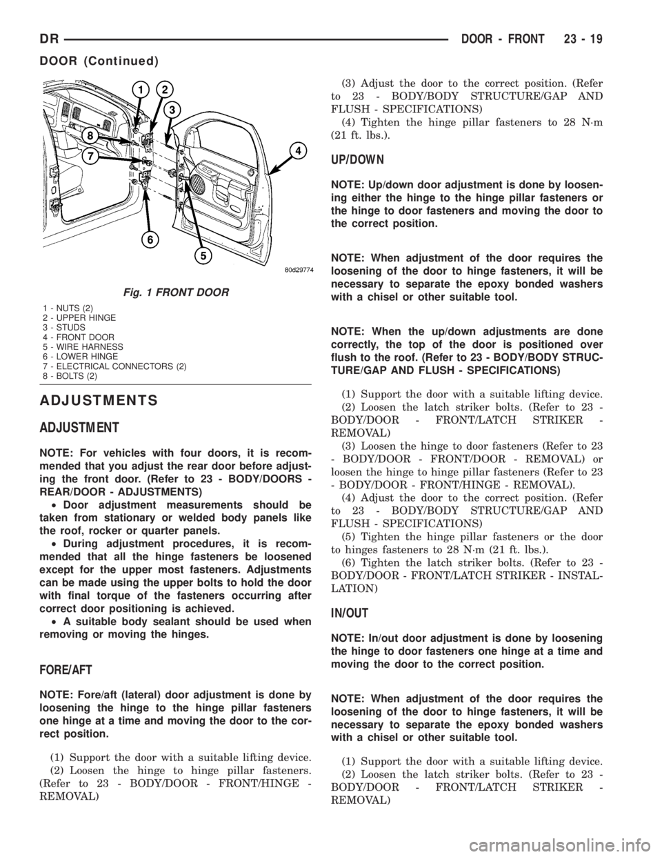
Fig. 1 FRONT DOOR
1 - NUTS (2)
2 - UPPER HINGE
3 - STUDS
4 - FRONT DOOR
5 - WIRE HARNESS
6 - LOWER HINGE
7 - ELECTRICAL CONNECTORS (2)
8 - BOLTS (2)
DRDOOR - FRONT 23 - 19
DOOR (Continued)
Page 2633 of 2895
INSTRUMENT PANEL CENTER
BEZEL
REMOVAL
WARNING: ON VEHICLES EQUIPPED WITH AIR-
BAGS, DISABLE THE AIRBAG SYSTEM BEFORE
ATTEMPTING ANY STEERING WHEEL, STEERING
COLUMN, SEAT BELT TENSIONER, OR INSTRU-
MENT PANEL COMPONENT DIAGNOSIS OR SER-
VICE. DISCONNECT AND ISOLATE THE BATTERY
NEGATIVE (GROUND) CABLE, THEN WAIT TWO
MINUTES FOR THE AIRBAG SYSTEM CAPACITOR
TO DISCHARGE BEFORE PERFORMING FURTHER
DIAGNOSIS OR SERVICE. THIS IS THE ONLY SURE
WAY TO DISABLE THE AIRBAG SYSTEM. FAILURE
TO TAKE THE PROPER PRECAUTIONS COULD
RESULT IN ACCIDENTAL AIRBAG DEPLOYMENT
AND POSSIBLE PERSONAL INJURY.
CAUTION: When removing and installing the center
bezel, use tape or other suitable material to protect
the cupholder and ash receiver from damage.
(1) Disconnect and isolate the negative battery
cable.
(2) Open the ashtray and cup holder.
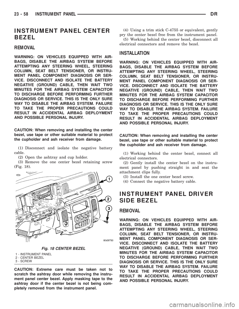
(3) Remove the one center bezel retaining screw
(Fig. 18).
CAUTION: Extreme care must be taken not to
scratch the ashtray door while removing the instru-
ment panel center bezel. Apply masking tape to the
ashtray door if the center bezel is not being com-
pletely removed from the instrument panel.(4) Using a trim stick C-4755 or equivalent, gently
pry the center bezel free from the instrument panel.
(5) Working behind the center bezel, disconnect all
electrical connectors and remove the bezel.INSTALLATION
WARNING: ON VEHICLES EQUIPPED WITH AIR-
BAGS, DISABLE THE AIRBAG SYSTEM BEFORE
ATTEMPTING ANY STEERING WHEEL, STEERING
COLUMN, SEAT BELT TENSIONER, OR INSTRU-
MENT PANEL COMPONENT DIAGNOSIS OR SER-
VICE. DISCONNECT AND ISOLATE THE BATTERY
NEGATIVE (GROUND) CABLE, THEN WAIT TWO
MINUTES FOR THE AIRBAG SYSTEM CAPACITOR
TO DISCHARGE BEFORE PERFORMING FURTHER
DIAGNOSIS OR SERVICE. THIS IS THE ONLY SURE
WAY TO DISABLE THE AIRBAG SYSTEM. FAILURE
TO TAKE THE PROPER PRECAUTIONS COULD
RESULT IN ACCIDENTAL AIRBAG DEPLOYMENT
AND POSSIBLE PERSONAL INJURY.
CAUTION: When removing and installing the center
bezel, use tape or other suitable material to protect
the cupholder and ash receiver from damage.
(1) Working behind the center bezel, connect all
electrical connectors.
(2) Gently install the center bezel on the instru-
ment panel by pushing straight in and seat the
attachment clips fully.
(3) Install the one center bezel screw.
(4) Connect the negative battery cable.
INSTRUMENT PANEL DRIVER
SIDE BEZEL
REMOVAL
WARNING: ON VEHICLES EQUIPPED WITH AIR-
BAGS, DISABLE THE AIRBAG SYSTEM BEFORE
ATTEMPTING ANY STEERING WHEEL, STEERING
COLUMN, SEAT BELT TENSIONER, OR INSTRU-
MENT PANEL COMPONENT DIAGNOSIS OR SER-
VICE. DISCONNECT AND ISOLATE THE BATTERY
NEGATIVE (GROUND) CABLE, THEN WAIT TWO
MINUTES FOR THE AIRBAG SYSTEM CAPACITOR
TO DISCHARGE BEFORE PERFORMING FURTHER
DIAGNOSIS OR SERVICE. THIS IS THE ONLY SURE
WAY TO DISABLE THE AIRBAG SYSTEM. FAILURE
TO TAKE THE PROPER PRECAUTIONS COULD
RESULT IN ACCIDENTAL AIRBAG DEPLOYMENT
AND POSSIBLE PERSONAL INJURY.
Fig. 18 CENTER BEZEL
1 - INSTRUMENT PANEL
2 - CENTER BEZEL
3 - SCREW
23 - 58 INSTRUMENT PANELDR
Page 2638 of 2895
INTERIOR
TABLE OF CONTENTS
page page
INTERIOR
CAUTION.............................63
4WD FLOOR SHIFT BOOT
REMOVAL.............................63
INSTALLATION.........................64
A-PILLAR TRIM/GRAB HANDLE
REMOVAL.............................64
INSTALLATION.........................64
B-PILLAR LOWER TRIM
REMOVAL.............................64
INSTALLATION.........................65
B-PILLAR UPPER TRIM
REMOVAL.............................65
INSTALLATION.........................65
CARPETS AND FLOOR MATS
REMOVAL.............................66
INSTALLATION.........................66
COAT HOOK
REMOVAL.............................67
INSTALLATION.........................67
COWL TRIM
REMOVAL.............................67
INSTALLATION.........................67
C-PILLAR LOWER TRIM
REMOVAL.............................67
INSTALLATION.........................68
C-PILLAR UPPER TRIM
REMOVAL.............................68
INSTALLATION.........................68
FLOOR CONSOLE
REMOVAL.............................68
INSTALLATION.........................68
HEADLINER
REMOVAL.............................69INSTALLATION.........................69
B-PILLAR GRAB HANDLE
REMOVAL.............................69
INSTALLATION.........................69
REAR CAB BACK PANEL TRIM
REMOVAL.............................70
INSTALLATION.........................70
REAR VIEW MIRROR
REMOVAL.............................71
INSTALLATION
INSTALLATION.......................71
INSTALLATION - REARVIEW MIRROR
SUPPORT BRACKET...................71
SUN VISOR
REMOVAL.............................71
INSTALLATION.........................71
SUN VISOR SUPPORT
REMOVAL.............................72
INSTALLATION.........................72
BODY VENT
REMOVAL.............................72
INSTALLATION.........................72
REAR DOOR SILL TRIM COVER
REMOVAL.............................72
INSTALLATION.........................72
LOAD FLOOR
REMOVAL.............................73
INSTALLATION.........................73
LOAD FLOOR SUPPORT CYLINDER
REMOVAL.............................73
INSTALLATION.........................73
INTERIOR
CAUTION
CAUTION:: Do not attempt to remove interior trim
panels/moldings without first removing the neces-
sary adjacent panels. To avoid damaging the pan-
els, ensure that all the screws and clips are
removed before attempting to remove an interior
trim panel/molding. Trim panels are somewhat flex-
ible but can be damaged if handled improperly.
4WD FLOOR SHIFT BOOT
REMOVAL
(1) Using a small pry bar or equivalent, remove
the insert, the nut and remove the shifter knob. (Fig.
2)
(2) Using a trim stick C-4755 or equivalent, pry up
the boot from the console. (Fig. 1)
DRINTERIOR 23 - 63
Page 2663 of 2895
WINDSHIELD
WARNING
WINDSHIELD SAFETY PRECAUTIONS
WARNING: DO NOT OPERATE THE VEHICLE
WITHIN 24 HOURS OF WINDSHIELD INSTALLATION.
IT TAKES AT LEAST 24 HOURS FOR URETHANE
ADHESIVE TO CURE. IF IT IS NOT CURED, THE
WINDSHIELD MAY NOT PERFORM PROPERLY IN
AN ACCIDENT.
²URETHANE ADHESIVES ARE APPLIED AS A
SYSTEM. USE GLASS CLEANER, GLASS PREP
SOLVENT, GLASS PRIMER, PVC (VINYL) PRIMER
AND PINCH WELD (FENCE) PRIMER PROVIDED BY
THE ADHESIVE MANUFACTURER. IF NOT, STRUC-
TURAL INTEGRITY COULD BE COMPROMISED.
²DAIMLERCHRYSLER DOES NOT RECOMMEND
GLASS ADHESIVE BY BRAND. TECHNICIANS
SHOULD REVIEW PRODUCT LABELS AND TECHNI-
CAL DATA SHEETS, AND USE ONLY ADHESIVES
THAT THEIR MANUFACTURES WARRANT WILL
RESTORE A VEHICLE TO THE REQUIREMENTS OF
FMVSS 212. TECHNICIANS SHOULD ALSO INSURE
THAT PRIMERS AND CLEANERS ARE COMPATIBLE
WITH THE PARTICULAR ADHESIVE USED.
²BE SURE TO REFER TO THE URETHANE MAN-
UFACTURER'S DIRECTIONS FOR CURING TIME
SPECIFICATIONS, AND DO NOT USE ADHESIVE
AFTER ITS EXPIRATION DATE.
²VAPORS THAT ARE EMITTED FROM THE URE-
THANE ADHESIVE OR PRIMER COULD CAUSE
PERSONAL INJURY. USE THEM IN A WELL-VENTI-
LATED AREA.
²SKIN CONTACT WITH URETHANE ADHESIVE
SHOULD BE AVOIDED. PERSONAL INJURY MAY
RESULT.
²ALWAYS WEAR EYE AND HAND PROTECTION
WHEN WORKING WITH GLASS.
CAUTION: Protect all painted and trimmed surfaces
from coming in contact with urethane or primers.
Be careful not to damage painted surfaces when
removing moldings or cutting urethane around
windshield.
REMOVAL
(1) Remove inside rear view mirror. (Refer to 23 -
BODY/INTERIOR/REAR VIEW MIRROR - REMOV-
AL).
(2) Remove cowl grill. (Refer to 23 - BODY/EXTE-
RIOR/COWL GRILLE - REMOVAL).
(3) Remove the a-pillar weatherstrip retainer.
(Refer to 23 - BODY/WEATHERSTRIP/SEALS/A-
PILLAR WEATHERSTRIP RETAINER - REMOVAL)
(4) Remove the a-pillar trim panels. (Refer to 23 -
BODY/INTERIOR/A-PILLAR TRIM - REMOVAL)
(5) Remove the headliner and from the inside of
the vehicle, cut the upper urethane bonding from
around windshield upper edge using a suitable sharp
cold knife (C-4849). A pneumatic cutting device can
be used but is not recommended. (Refer to 23 -
BODY/INTERIOR/HEADLINER - REMOVAL)
(6) From the outside of the vehicle, cut urethane
bonding from the remaining sides of the windshield
using a suitable sharp cold knife (C-4849). A pneu-
matic cutting device can be used but is not recom-
mended.
(7) Separate windshield from vehicle.
INSTALLATION
WARNING: Allow the urethane at least 24 hours to
cure before returning the vehicle to use.
CAUTION: Roll down the left and right front door
glass and open the rear glass slider (if available)
before installing windshield to avoid pressurizing
the passenger compartment if a door is slammed
before urethane is cured. Water leaks can result.
The windshield fence should be cleaned of most of
its old urethane bonding material. A small amount of
old urethane, approximately 1-2 mm in height,
should remain on the fence. Do not grind off or com-
pletely remove all old urethane from the fence, the
paint finish and bonding strength will be adversely
affected.
(1) Place replacement windshield into windshield
opening and position glass in the center of the open-
ing against the support spacers. Mark the outside
surface of the glass at the support spacers with a
grease pencil or pieces of masking tape and ink pen
to use as a reference for installation. Remove replace-
ment windshield from windshield opening (Fig. 5).
(2) Position the windshield inside up on a suitable
work surface with two padded, wood 10 cm by 10 cm
by 50 cm (4 in. by 4 in. by 20 in.) blocks, placed par-
allel 75 cm (2.5 ft.) apart (Fig. 6).
(3) Clean inside of windshield with MOPAR Glass
Cleaner and lint-free cloth.
23 - 88 STATIONARY GLASSDR
Page 2802 of 2895
(3) Plug in the blower motor wire harness connec-
tor.
(4) Connect the battery negative cable.
DEFROST DOOR
REMOVAL - DEFROST DOOR
WARNING: ON VEHICLES EQUIPPED WITH AIR-
BAGS, DISABLE THE AIRBAG SYSTEM BEFORE
ATTEMPTING ANY STEERING WHEEL, STEERING
COLUMN, OR INSTRUMENT PANEL COMPONENT
DIAGNOSIS OR SERVICE. DISCONNECT AND ISO-
LATE THE BATTERY NEGATIVE (GROUND) CABLE,
THEN WAIT TWO MINUTES FOR THE AIRBAG SYS-
TEM CAPACITOR TO DISCHARGE BEFORE PER-
FORMING FURTHER DIAGNOSIS OR SERVICE. THIS
IS THE ONLY SURE WAY TO DISABLE THE AIRBAG
SYSTEM. FAILURE TO TAKE THE PROPER PRE-
CAUTIONS COULD RESULT IN AN ACCIDENTAL
AIRBAG DEPLOYMENT AND POSSIBLE PERSONAL
INJURY.
WARNING: (Refer to 24 - HEATING & AIR CONDI-
TIONING/PLUMBING - WARNING) and (Refer to 24 -
HEATING & AIR CONDITIONING/PLUMBING - CAU-
TION).
(1) Recover refrigerant(Refer to 24 - HEATING &
AIR CONDITIONING/PLUMBING - STANDARD
PROCEDURE).
(2) Remove and disassemble the HVAC housing.
(Refer to 24 - HEATING & AIR CONDITIONING/
DISTRIBUTION/HVAC HOUSING - REMOVAL)
(Refer to 24 - HEATING & AIR CONDITIONING/
DISTRIBUTION/HVAC HOUSING - DISASSEMBLY)
(3) Remove the defrost door actuator.
(4) Remove the defrost door from the HVAC hous-
ing, by first removing the actuator if not already
removed. Then carefully move the door so that one
pivot point cleans then tilt and lift the door out of
the HVAC housing.
INSTALLATION - DEFROST DOOR
(1) Install the defrost door in the HVAC housing.
(2) Install the defrost door actuator.
(3) Assemble the HVAC housing. (Refer to 24 -
HEATING & AIR CONDITIONING/DISTRIBUTION/
HVAC HOUSING - ASSEMBLY)
(4) Install the HVAC housing in the vehicle. (Refer
to 24 - HEATING & AIR CONDITIONING/DISTRI-
BUTION/HVAC HOUSING - INSTALLATION)
(5) Run calibration test.
FLOOR DISTRIBUTION DUCTS
REMOVAL
WARNING: ON VEHICLES EQUIPPED WITH AIR-
BAGS, DISABLE THE AIRBAG SYSTEM BEFORE
ATTEMPTING ANY STEERING WHEEL, STEERING
COLUMN, OR INSTRUMENT PANEL COMPONENT
DIAGNOSIS OR SERVICE. DISCONNECT AND ISO-
LATE THE BATTERY NEGATIVE (GROUND) CABLE,
THEN WAIT TWO MINUTES FOR THE AIRBAG SYS-
TEM CAPACITOR TO DISCHARGE BEFORE PER-
FORMING FURTHER DIAGNOSIS OR SERVICE. THIS
IS THE ONLY SURE WAY TO DISABLE THE AIRBAG
SYSTEM. FAILURE TO TAKE THE PROPER PRE-
CAUTIONS COULD RESULT IN AN ACCIDENTAL
AIRBAG DEPLOYMENT AND POSSIBLE PERSONAL
INJURY.
(1) Remove the screws that secure the floor duct to
the HVAC housing.
(2) Remove the floor duct from the HVAC housing.
INSTALLATION
(1) Install the floor duct on the HVAC housing.
(2) Install the screws that secure the floor duct to
the HVAC housing. Tighten the mounting screws to
2.2 N´m (20 in. lbs.).
(3) Install the battery negative cable.
HVAC HOUSING
REMOVAL
WARNING: ON VEHICLES EQUIPPED WITH AIR-
BAGS, DISABLE THE AIRBAG SYSTEM BEFORE
ATTEMPTING ANY STEERING WHEEL, STEERING
COLUMN, OR INSTRUMENT PANEL COMPONENT
DIAGNOSIS OR SERVICE. DISCONNECT AND ISO-
LATE THE BATTERY NEGATIVE (GROUND) CABLE,
THEN WAIT TWO MINUTES FOR THE AIRBAG SYS-
TEM CAPACITOR TO DISCHARGE BEFORE PER-
FORMING FURTHER DIAGNOSIS OR SERVICE. THIS
IS THE ONLY SURE WAY TO DISABLE THE AIRBAG
SYSTEM. FAILURE TO TAKE THE PROPER PRE-
CAUTIONS COULD RESULT IN AN ACCIDENTAL
AIRBAG DEPLOYMENT AND POSSIBLE PERSONAL
INJURY.
(1) Disconnect and isolate the battery negative
cable.
(2) Remove the instrument panel from the vehi-
cle(Refer to 23 - BODY/INSTRUMENT PANEL -
REMOVAL).
DRDISTRIBUTION 24 - 27
BLOWER MOTOR (Continued)