2003 DODGE RAM TiminG chain guide
[x] Cancel search: TiminG chain guidePage 1516 of 2895
(5) Raise the transmission enough to remove the
mount from the crossmember.
(6) Remove the mount.
INSTALLATION
NOTE: Threadlocking compound must be applied to
the bolts before installation.
(1) Install the two bolts that attach the transmis-
sion mount to the transmission bracket.
(2) Torque the bolts to 61N´m (45 ft.lbs.) torque.
(3) Lower the transmission so the transmission
mount rests on the crossmember, and the studs of
the transmission mount are aligned in the slots in
the crossmember.
(4) Install the nuts onto the transmission mount
studs through the crossmember access slot.
(5) Torque the nuts to 54N´m (40 ft. lbs.).
LUBRICATION
DESCRIPTION
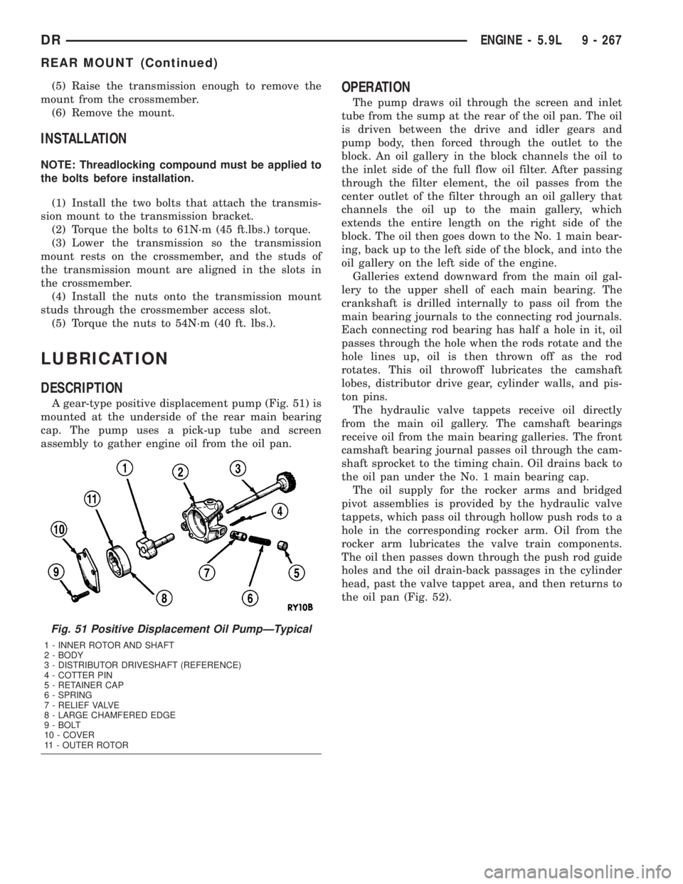
A gear-type positive displacement pump (Fig. 51) is
mounted at the underside of the rear main bearing
cap. The pump uses a pick-up tube and screen
assembly to gather engine oil from the oil pan.
OPERATION
The pump draws oil through the screen and inlet
tube from the sump at the rear of the oil pan. The oil
is driven between the drive and idler gears and
pump body, then forced through the outlet to the
block. An oil gallery in the block channels the oil to
the inlet side of the full flow oil filter. After passing
through the filter element, the oil passes from the
center outlet of the filter through an oil gallery that
channels the oil up to the main gallery, which
extends the entire length on the right side of the
block. The oil then goes down to the No. 1 main bear-
ing, back up to the left side of the block, and into the
oil gallery on the left side of the engine.
Galleries extend downward from the main oil gal-
lery to the upper shell of each main bearing. The
crankshaft is drilled internally to pass oil from the
main bearing journals to the connecting rod journals.
Each connecting rod bearing has half a hole in it, oil
passes through the hole when the rods rotate and the
hole lines up, oil is then thrown off as the rod
rotates. This oil throwoff lubricates the camshaft
lobes, distributor drive gear, cylinder walls, and pis-
ton pins.
The hydraulic valve tappets receive oil directly
from the main oil gallery. The camshaft bearings
receive oil from the main bearing galleries. The front
camshaft bearing journal passes oil through the cam-
shaft sprocket to the timing chain. Oil drains back to
the oil pan under the No. 1 main bearing cap.
The oil supply for the rocker arms and bridged
pivot assemblies is provided by the hydraulic valve
tappets, which pass oil through hollow push rods to a
hole in the corresponding rocker arm. Oil from the
rocker arm lubricates the valve train components.
The oil then passes down through the push rod guide
holes and the oil drain-back passages in the cylinder
head, past the valve tappet area, and then returns to
the oil pan (Fig. 52).
Fig. 51 Positive Displacement Oil PumpÐTypical
1 - INNER ROTOR AND SHAFT
2 - BODY
3 - DISTRIBUTOR DRIVESHAFT (REFERENCE)
4 - COTTER PIN
5 - RETAINER CAP
6 - SPRING
7 - RELIEF VALVE
8 - LARGE CHAMFERED EDGE
9 - BOLT
10 - COVER
11 - OUTER ROTOR
DRENGINE - 5.9L 9 - 267
REAR MOUNT (Continued)
Page 1632 of 2895
INSTALLATION
When a crankshaft is replaced, all main and con-
necting rod bearings should be replaced with new
bearings. Therefore, selective fitting of the bearings
is not required when a crankshaft and bearings are
replaced.
NOTE: Lubricate crankshaft main bearings with
clean engine oil.
(1) Position upper main bearings into block.
(2) Position the crankshaft into the cylinder block.
(3) Lubricate the main journals with clean engine
oil. Install upper main bearings, caps and bolts. Fol-
low the 2 step tightening sequence, starting with
main bearing cap 1.
(4) Lubricate the connecting rod bearings and jour-
nals with clean engine oil. Carefully install connect-
ing rods to the crankshaft.
(5) Using Special Tool 8359 Seal Installer install
new oil into oil seal retainer.
(6) Using Special Tool 6687 Guide, install the rear
seal retainer with a new gasket.
(7) Install the timing chain cover with a new gas-
ket and oil seal.
(8) Prime oil pump by squirt oil in the oil filter
mounting hole and filling the J-trap of the front tim-
ing cover. When oil is running out, install oil filter
that has been filled with oil.(9) Apply a rearward axial load of 667 N (150
lbs-f) on crankshaft centerline, driving No.3 main cap
and thrust bearing against No.3 bulkhead. Repeat
procedure, driving crankshaft forward to align rear
flange of thrust bearings in a common plane. Front
face of No.1 main cap must not extend forward in
front of face of No.1 bulkhead.
(10) Install the oil pickup tube. Tighten the bolts
to 16 N´m (144 in. lbs.) torque.
(11) Install the oil pan.
CRANKSHAFT MAIN
BEARINGS
STANDARD PROCEDUREÐFITTING
CRANKSHAFT MAIN BEARINGS
Bearing caps are not interchangeable and should
be marked at removal to ensure correct assembly.
Upper and lower bearing halves are NOT inter-
changeable. All lower main bearing halves are inter-
changeable. Upper main bearing halves of No. 2, 4,
and 5 are interchangeable. Upper main bearing
halves of No. 1 and 6 are interchangeable, this also
applies to the lower bearing halves.
The No.3 main bearing is flanged to carry the
crankshaft thrust loads. This bearing is NOT inter-
changeable with any other bearing halves in the
engine. Bearing shells are available in standard and
the following undersizes: 0.25 mm (0.001 inch), 0.051
mm (0.002 inch), 0.076 mm (0.003 inch), 0.254 mm
(0.010 inch) and 0.305 mm (0.012 inch). Never install
an undersize bearing that will reduce clearance
below specifications.
REMOVAL
(1) Remove the oil pan and oil pump pick-up tube
(Refer to 9 - ENGINE/LUBRICATION/OIL PAN -
REMOVAL).
(2) Identify bearing caps before removal. Remove
bearing caps one at a time.
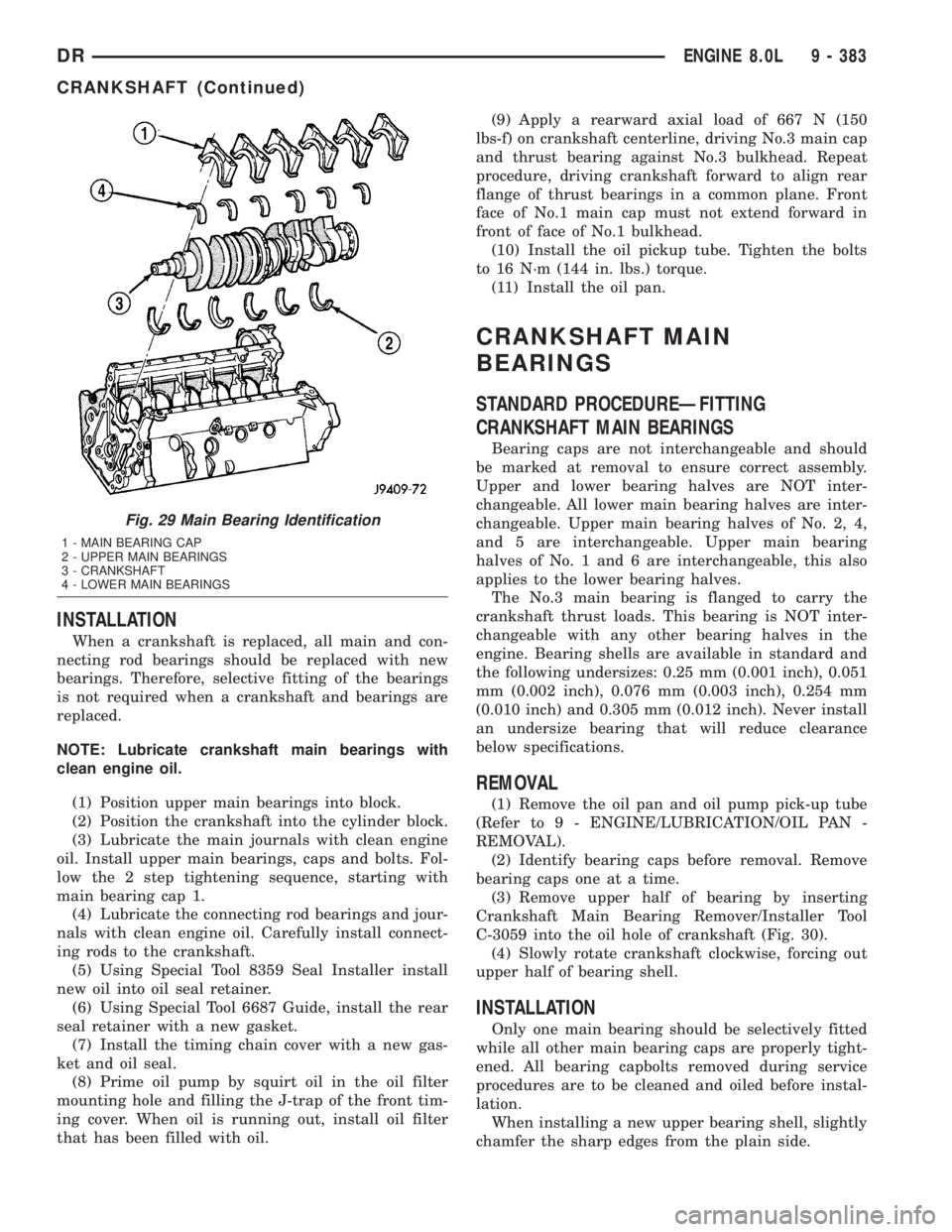
(3) Remove upper half of bearing by inserting
Crankshaft Main Bearing Remover/Installer Tool
C-3059 into the oil hole of crankshaft (Fig. 30).
(4) Slowly rotate crankshaft clockwise, forcing out
upper half of bearing shell.
INSTALLATION
Only one main bearing should be selectively fitted
while all other main bearing caps are properly tight-
ened. All bearing capbolts removed during service
procedures are to be cleaned and oiled before instal-
lation.
When installing a new upper bearing shell, slightly
chamfer the sharp edges from the plain side.
Fig. 29 Main Bearing Identification
1 - MAIN BEARING CAP
2 - UPPER MAIN BEARINGS
3 - CRANKSHAFT
4 - LOWER MAIN BEARINGS
DRENGINE 8.0L 9 - 383
CRANKSHAFT (Continued)
Page 1634 of 2895
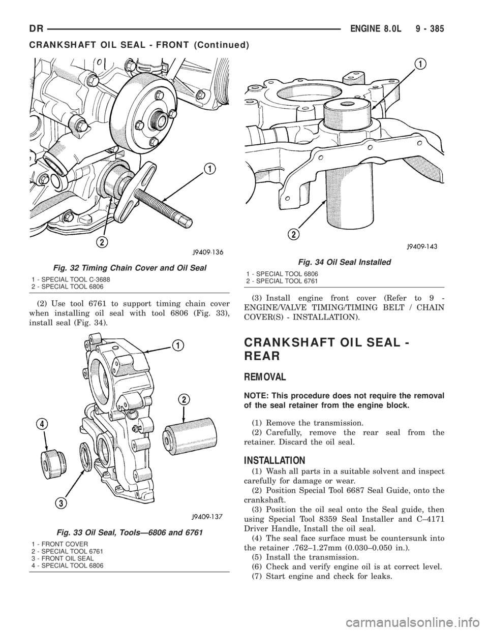
(2) Use tool 6761 to support timing chain cover
when installing oil seal with tool 6806 (Fig. 33),
install seal (Fig. 34).(3) Install engine front cover (Refer to 9 -
ENGINE/VALVE TIMING/TIMING BELT / CHAIN
COVER(S) - INSTALLATION).
CRANKSHAFT OIL SEAL -
REAR
REMOVAL
NOTE: This procedure does not require the removal
of the seal retainer from the engine block.
(1) Remove the transmission.
(2) Carefully, remove the rear seal from the
retainer. Discard the oil seal.
INSTALLATION
(1) Wash all parts in a suitable solvent and inspect
carefully for damage or wear.
(2) Position Special Tool 6687 Seal Guide, onto the
crankshaft.
(3) Position the oil seal onto the Seal guide, then
using Special Tool 8359 Seal Installer and C±4171
Driver Handle, Install the oil seal.
(4) The seal face surface must be countersunk into
the retainer .762±1.27mm (0.030±0.050 in.).
(5) Install the transmission.
(6) Check and verify engine oil is at correct level.
(7) Start engine and check for leaks.
Fig. 32 Timing Chain Cover and Oil Seal
1 - SPECIAL TOOL C-3688
2 - SPECIAL TOOL 6806
Fig. 33 Oil Seal, ToolsÐ6806 and 6761
1 - FRONT COVER
2 - SPECIAL TOOL 6761
3 - FRONT OIL SEAL
4 - SPECIAL TOOL 6806
Fig. 34 Oil Seal Installed
1 - SPECIAL TOOL 6806
2 - SPECIAL TOOL 6761
DRENGINE 8.0L 9 - 385
CRANKSHAFT OIL SEAL - FRONT (Continued)
Page 1643 of 2895
from the center outlet of the filter through an oil gal-
lery that channels the oil up to the tappet galleries,
which extends the entire length of block.
Galleries extend downward from the main oil gal-
lery to the upper shell of each main bearing. The
crankshaft is drilled internally to pass oil from the
main bearing journals to the connecting rod journals.
Each connecting rod bearing has half a hole in it, oil
passes through the hole when the rods rotate and the
hole lines up, oil is then thrown off as the rod
rotates. This oil throwoff lubricates the camshaft
lobes, cylinder walls, and piston pins.
The hydraulic valve tappets receive oil directly
from the main oil gallery. The camshaft bearings
receive oil from the main bearing galleries. The front
camshaft bearing journal passes oil through the cam-
shaft sprocket to the timing chain. Oil drains back to
the oil pan under the No. 1 main bearing cap.
The oil supply for the rocker arms and bridged
pivot assemblies is provided by the hydraulic valve
tappets, which pass oil through hollow push rods to a
hole in the corresponding rocker arm. Oil from the
rocker arm lubricates the valve train components.
The oil then passes down through the push rod guide
holes and the oil drain-back passages in the cylinder
head, past the valve tappet area, and then returns to
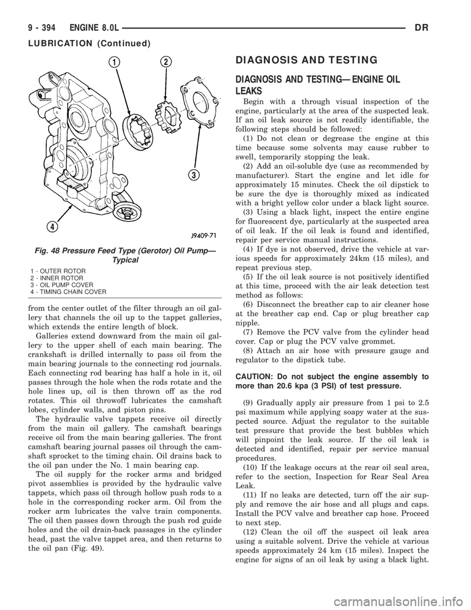
the oil pan (Fig. 49).
DIAGNOSIS AND TESTING
DIAGNOSIS AND TESTINGÐENGINE OIL
LEAKS
Begin with a through visual inspection of the
engine, particularly at the area of the suspected leak.
If an oil leak source is not readily identifiable, the
following steps should be followed:
(1) Do not clean or degrease the engine at this
time because some solvents may cause rubber to
swell, temporarily stopping the leak.
(2) Add an oil-soluble dye (use as recommended by
manufacturer). Start the engine and let idle for
approximately 15 minutes. Check the oil dipstick to
be sure the dye is thoroughly mixed as indicated
with a bright yellow color under a black light source.
(3) Using a black light, inspect the entire engine
for fluorescent dye, particularly at the suspected area
of oil leak. If the oil leak is found and identified,
repair per service manual instructions.
(4) If dye is not observed, drive the vehicle at var-
ious speeds for approximately 24km (15 miles), and
repeat previous step.
(5) If the oil leak source is not positively identified
at this time, proceed with the air leak detection test
method as follows:
(6) Disconnect the breather cap to air cleaner hose
at the breather cap end. Cap or plug breather cap
nipple.
(7) Remove the PCV valve from the cylinder head
cover. Cap or plug the PCV valve grommet.
(8) Attach an air hose with pressure gauge and
regulator to the dipstick tube.
CAUTION: Do not subject the engine assembly to
more than 20.6 kpa (3 PSI) of test pressure.
(9) Gradually apply air pressure from 1 psi to 2.5
psi maximum while applying soapy water at the sus-
pected source. Adjust the regulator to the suitable
test pressure that provide the best bubbles which
will pinpoint the leak source. If the oil leak is
detected and identified, repair per service manual
procedures.
(10) If the leakage occurs at the rear oil seal area,
refer to the section, Inspection for Rear Seal Area
Leak.
(11) If no leaks are detected, turn off the air sup-
ply and remove the air hose and all plugs and caps.
Install the PCV valve and breather cap hose. Proceed
to next step.
(12) Clean the oil off the suspect oil leak area
using a suitable solvent. Drive the vehicle at various
speeds approximately 24 km (15 miles). Inspect the
engine for signs of an oil leak by using a black light.
Fig. 48 Pressure Feed Type (Gerotor) Oil PumpÐ
Typical
1 - OUTER ROTOR
2 - INNER ROTOR
3 - OIL PUMP COVER
4 - TIMING CHAIN COVER
9 - 394 ENGINE 8.0LDR
LUBRICATION (Continued)
Page 2887 of 2895
SIDE - REMOVAL, LEFT................9-121
SIDE - REMOVAL, RIGHT..............9-121
SIDE BEZEL - INSTALLATION,
INSTRUMENT PANEL DRIVER...........23-59
SIDE BEZEL - REMOVAL, INSTRUMENT
PANEL DRIVER......................23-58
SIDE CURTAIN AIRBAG - DESCRIPTION . . . 8O-51
SIDE CURTAIN AIRBAG - INSTALLATION . . 8O-53
SIDE CURTAIN AIRBAG - OPERATION....8O-51
SIDE CURTAIN AIRBAG - REMOVAL......8O-52
SIDE IMPACT AIRBAG CONTROL
MODULE - DESCRIPTION..............8O-53
SIDE IMPACT AIRBAG CONTROL
MODULE - OPERATION................8O-54
SIDE MOLDINGS - INSTALLATION, BODY . . 23-36
SIDE MOLDINGS - REMOVAL, BODY.....23-36
SIDE VIEW MIRROR - INSTALLATION.....23-41
SIDE VIEW MIRROR - REMOVAL........23-41
SIDE VIEW MIRROR FLAG -
INSTALLATION.......................23-27
SIDE VIEW MIRROR FLAG - REMOVAL . . . 23-27
SIDE VIEW MIRROR GLASS -
INSTALLATION.......................23-44
SIDE VIEW MIRROR GLASS - REMOVAL . . 23-42
SIDEVIEW MIRROR - REMOVAL.........8N-13
SIGNAL INDICATOR - DESCRIPTION,
TURN..............................8J-39
SIGNAL INDICATOR - OPERATION, TURN . . 8J-39
SIGNAL LAMP - INSTALLATION,
PARK/TURN.........................8L-21
SIGNAL LAMP - REMOVAL, PARK/TURN . . 8L-21
SIGNAL SYSTEM - DESCRIPTION, TURN . . 8L-17
SIGNAL SYSTEM - OPERATION, TURN....8L-18
SILL TRIM COVER - INSTALLATION,
REAR DOOR........................23-72
SILL TRIM COVER - REMOVAL, REAR
DOOR.............................23-72
SINGLE CARDAN UNIVERSAL JOINTS -
ASSEMBLY...........................3-9
SINGLE CARDAN UNIVERSAL JOINTS -
DISASSEMBLY.........................3-9
SIZE, SPARE WHEEL WITH MATCHING
TIRE - DESCRIPTION, FULL............22-15
SKID PLATE - INSTALLATION, FRONT.....13-24
SKID PLATE - INSTALLATION, TRANSFER
CASE..............................13-26
SKID PLATE - REMOVAL, FRONT........13-24
SKID PLATE - REMOVAL, TRANSFER
CASE..............................13-26
SLEEVE - INSTALLATION, HEADREST.....23-82
SLEEVE - REMOVAL, HEADREST........23-82
SMOKE DIAGNOSIS CHARTS -
DIAGNOSIS AND TESTING.............9-285
SOLENOID - DESCRIPTION......21-253,21-431
SOLENOID - DESCRIPTION, EVAP/PURGE . 25-12
SOLENOID - INSTALLATION, EVAP/
PURGE.............................25-13
SOLENOID - OPERATION........21-254,21-431
SOLENOID - OPERATION, EVAP/PURGE . . . 25-12
SOLENOID - REMOVAL, EVAP/PURGE.....25-13
SOLENOID SWITCH VALVE -
DESCRIPTION......................21-574
SOLENOID SWITCH VALVE - OPERATION . 21-574
SOLENOIDS - DESCRIPTION...........21-574
SOLENOIDS - OPERATION.............21-575
SOLENOID/TRS ASSEMBLY -
DESCRIPTION, TRANSMISSION........21-582
SOLENOID/TRS ASSEMBLY -
INSTALLATION, TRANSMISSION........21-583
SOLENOID/TRS ASSEMBLY -
OPERATION, TRANSMISSION..........21-582
SOLENOID/TRS ASSEMBLY - REMOVAL,
TRANSMISSION.....................21-583
SOLID LIFTERS/TAPPETS - CLEANING....9-328
SOLID LIFTERS/TAPPETS - INSPECTION . . 9-328
SOLID LIFTERS/TAPPETS -
INSTALLATION.......................9-328
SOLID LIFTERS/TAPPETS - REMOVAL....9-327
SPARE / TEMPORARY TIRE -
DESCRIPTION.......................22-15
SPARE TIRE / TEMPORARY -
DESCRIPTION........................22-5
SPARE WHEEL WITH MATCHING TIRE -
DESCRIPTION, FULL SIZE
..............22-15
SPARK PLUG - DESCRIPTION
...........8I-27
SPARK PLUG - REMOVAL
..............8I-30
SPARK PLUG CABLE - DESCRIPTION
.....8I-33
SPARK PLUG CABLE - INSTALLATION
.....8I-35SPARK PLUG CABLE - OPERATION.......8I-33
SPARK PLUG CABLE - REMOVAL........8I-34
SPARK PLUG CABLE ORDER, 8.0L V-10
ENGINE..............................8I-5
SPARK PLUG CABLE RESISTANCE,
SPECIFICATIONS......................8I-5
SPARK PLUG CABLES - DIAGNOSIS AND
TESTING............................8I-33
SPARK PLUG CONDITIONS - DIAGNOSIS
AND TESTING........................8I-27
SPARK PLUGS, SPECIFICATIONS..........8I-5
SPEAKER - DESCRIPTION..............8A-12
SPEAKER - DIAGNOSIS AND TESTING....8A-13
SPEAKER - INSTALLATION.............8A-15
SPEAKER - OPERATION...............8A-12
SPEAKER - REMOVAL.................8A-13
SPECIFICATIONS......................7-20
SPEED CONTROL - DESCRIPTION........8P-1
SPEED CONTROL - OPERATION..........8P-2
SPEED CONTROL - TORQUE.............8P-3
SPEED SENSOR - DESCRIPTION . . 21-254,21-431
SPEED SENSOR - DESCRIPTION, FRONT
WHEEL.............................5-41
SPEED SENSOR - DESCRIPTION, INPUT . 21-558
SPEED SENSOR - DESCRIPTION,
OUTPUT...........................21-567
SPEED SENSOR - DIAGNOSIS AND
TESTING, REAR WHEEL................5-43
SPEED SENSOR - INSTALLATION, FRONT
WHEEL.............................5-42
SPEED SENSOR - INSTALLATION, INPUT . 21-559
SPEED SENSOR - INSTALLATION,
OUTPUT...........................21-567
SPEED SENSOR - INSTALLATION, REAR
WHEEL.............................5-43
SPEED SENSOR - OPERATION . . . 21-254,21-431
SPEED SENSOR - OPERATION, FRONT
WHEEL.............................5-41
SPEED SENSOR - OPERATION, INPUT . . . 21-558
SPEED SENSOR - OPERATION, OUTPUT . . 21-567
SPEED SENSOR - REMOVAL, FRONT
WHEEL.............................5-41
SPEED SENSOR - REMOVAL, INPUT.....21-559
SPEED SENSOR - REMOVAL, OUTPUT . . . 21-567
SPEED SENSOR - REMOVAL, REAR
WHEEL.............................5-42
SPEEDOMETER - DESCRIPTION.........8J-36
SPEEDOMETER - OPERATION...........8J-36
SPEEDS - DESCRIPTION, TIRE
PRESSURE FOR HIGH..................22-6
SPLASH SHIELD - INSTALLATION,
FRONT WHEELHOUSE.................23-41
SPLASH SHIELD - INSTALLATION, REAR
WHEELHOUSE.......................23-41
SPLASH SHIELD - REMOVAL, FRONT
WHEELHOUSE.......................23-40
SPLASH SHIELD - REMOVAL, REAR
WHEELHOUSE.......................23-41
SPLICE INFORMATION - DESCRIPTION,
CONNECTOR, GROUND..............8W-01-7
SPLICING - STANDARD PROCEDURE,
WIRE...........................8W-01-15
SPRING - DESCRIPTION................2-41
SPRING - INSTALLATION.......2-22,2-36,2-41
SPRING - OPERATION..................2-41
SPRING - REMOVAL...........2-21,2-36,2-41
SPRING AND SHOCK - DIAGNOSIS AND
TESTING............................2-38
SPRING BUMPERS (3500) -
INSTALLATION, AUXILIARY..............2-40
SPRING BUMPERS (3500) - REMOVAL,
AUXILIARY..........................2-40
SPRING TIP INSERTS - INSTALLATION....2-42
SPRING TIP INSERTS - REMOVAL........2-41
SPRINGS - DESCRIPTION, VALVE . . . 9-125,9-31,
9-36
SPRINGS - INSTALLATION, VALVE . . 9-126,9-199,
9-31,9-37
SPRINGS - INSTALLATION, VALVES AND
VALVE
.............................9-379
SPRINGS - REMOVAL, VALVE
. 9-125,9-199,9-31,
9-37
SPRINGS - REMOVAL, VALVES AND
VALVE
.............................9-377
SPRINGS - STANDARD PROCEDURE,
VALVES, GUIDES
................9-246,9-305
SPRINGS AND SEALS - REMOVAL,
VALVE
.............................9-308SPROCKETS - INSPECTION, TIMING
BELT/CHAIN.....................9-171,9-83
SPROCKETS - INSTALLATION, TIMING
BELT/CHAIN...........9-172,9-279,9-406,9-84
SPROCKETS - INSTALLATION,
TIMING/CHAIN.......................9-222
SPROCKETS - REMOVAL, TIMING
BELT/CHAIN...........9-169,9-279,9-405,9-81
SPROCKETS - REMOVAL, TIMING/CHAIN . . 9-221
SQUEAK & RATTLE - STANDARD
PROCEDURE, BUZZ...................23-11
STABILIZER BAR - DESCRIPTION.........2-24
STABILIZER BAR - INSTALLATION....2-24,2-37
STABILIZER BAR - OPERATION...........2-24
STABILIZER BAR - REMOVAL........2-24,2-37
STAKING - STANDARD PROCEDURE,
HEAT ...............................23-3
STANDARD CAB - INSTALLATION........8O-31
STANDARD CAB - REMOVAL...........8O-28
STARTER MOTOR - DIAGNOSIS AND
TESTING...........................8F-34
STARTER MOTOR - INSTALLATION.......8F-37
STARTER MOTOR - REMOVAL..........8F-34
STARTER MOTOR RELAY - DESCRIPTION . 8F-38
STARTER MOTOR RELAY -
INSTALLATION.......................8F-39
STARTER MOTOR RELAY - OPERATION . . . 8F-38
STARTER MOTOR RELAY - REMOVAL.....8F-39
STARTER RELAY - DIAGNOSIS AND
TESTING.............................8F-38
STARTING - DESCRIPTION.............8F-28
STARTING - OPERATION...............8F-28
STARTING - STANDARD PROCEDURE,
JUMP...............................0-13
STARTING SYSTEM - DIAGNOSIS AND
TESTING...........................8F-29
STARTING SYSTEM - SPECIFICATIONS,
TORQUE............................8F-34
STARTING SYSTEM, SPECIFICATIONS.....8F-33
STATE DISPLAY TEST MODE -
DESCRIPTION........................25-1
STEERING - DESCRIPTION..............19-1
STEERING - OPERATION................19-1
STEERING COLUMN - DIAGNOSIS AND
TESTING............................19-7
STEERING COLUMN OPENING COVER -
INSTALLATION.......................23-61
STEERING COLUMN OPENING COVER -
REMOVAL..........................23-61
STEERING COLUMN OPENING SUPPORT
BRACKET - INSTALLATION.............23-62
STEERING COLUMN OPENING SUPPORT
BRACKET - REMOVAL.................23-61
STEERING COUPLING - INSTALLATION,
UPPER.............................19-14
STEERING COUPLING - REMOVAL,
UPPER.............................19-13
STEERING FLOW AND PRESSURE -
DIAGNOSIS AND TESTING, POWER.......19-4
STEERING FLUID - DESCRIPTION,
POWER..............................0-3
STEERING FLUID LEVEL CHECKING -
STANDARD PROCEDURE, POWER.......19-42
STEERING GEAR INPUT SHAFT SEAL -
INSTALLATION.......................19-28
STEERING GEAR INPUT SHAFT SEAL -
REMOVAL..........................19-25
STEERING GEAR, SPECIAL TOOLS -
POWER............................19-22
STEERING GEAR, SPECIFICATIONS -
POWER............................19-21
STEERING LINKAGE, SPECIAL TOOLS....19-35
STEERING PRESSURE SWITCH -
DESCRIPTION, POWER................19-45
STEERING PRESSURE SWITCH -
OPERATION, POWER..................19-45
STEERING PUMP - INITIAL OPERATION -
STANDARD PROCEDURE, POWER.......19-39
STEERING, SPECIAL TOOLS.............19-5
STEERING SYSTEM - DIAGNOSIS AND
TESTING, POWER.....................19-2
STEERING SYSTEM - STANDARD
PROCEDURE, FLUSHING POWER
........19-39
STEERING WHEEL - INSTALLATION
......19-15
STEERING WHEEL - REMOVAL
..........19-15
STEM SEAL - INSTALLATION, VALVE
.....9-378
STEM SEALS - DESCRIPTION, VALVE
....9-126,
9-198
32 INDEXDR
Description Group-Page Description Group-Page Description Group-Page