2003 DODGE RAM glove box
[x] Cancel search: glove boxPage 366 of 2895

CONDITION POSSIBLE CAUSES CORRECTION
CLOCK WILL NOT KEEP
SET TIME1. Fuse faulty. 1. Check Ignition-Off Draw (IOD) fuse in the
Integrated Power Module (IPM). Replace fuse, if
required.
2. Radio connector faulty. 2. Check for loose or corroded radio connector.
Repair, if required.
3. Wiring faulty. 3. Check for battery voltage at radio connector.
Repair wiring, if required.
4. Radio ground faulty. 4. Check for continuity between radio chassis and
a known good ground. There should be
continuity. Repair ground, if required.
5. Radio faulty. 5. Refer to appropriate Diagnostic Service
Manual.
POOR RADIO RECEPTION 1. Antenna faulty. 1. (Refer to 8 - ELECTRICAL/AUDIO/ANTENNA
BODY & CABLE - DIAGNOSIS AND TESTING).
2. Radio ground faulty. 2. Check for continuity between radio chassis and
a known good ground. There should be
continuity. Repair ground, if required.
3. Radio noise suppression
faulty.3. Repair or replace ground strap as necessary.
4. Radio faulty. 4. Refer to appropriate Diagnostic Service
Manual.
NO/POOR TAPE
OPERATION1. Faulty tape. 1. Insert known good tape and test operation.
2. Foreign objects behind
tape door.2. Remove foreign objects and test operation.
3. Dirty cassette tape head. 3. Clean head with Mopar Cassette Head
Cleaner.
4. Faulty tape deck. 4. Exchange or replace radio, if required.
NO COMPACT DISC
OPERATION1. Faulty CD. 1. Insert known good CD and test operation.
2. Foreign material on CD. 2. Clean CD and test operation.
3. Condensation on CD or
optics.3. Allow temperature of vehicle interior to stabilize
and test operation.
4. Faulty CD player. 4. Refer to appropriate Diagnostic Service
Manual.
AMPLIFIER
DESCRIPTION
The optional Infinity premium speaker system
includes a separate Infinity audio power amplifier.
The amplifier is a six channel unit and is rated at
240 total output watts. The amplifier is located
behind the glove box.
OPERATION
The power amplifier electronically increases the
frequency response of the normal audio signal output
from the radio amplifier in order to improve the
acoustic performance of the speakers. On vehiclesequipped with an amplifier, the amplifier section of
the radio becomes a pre-amplifier.
The amplifier receives audio signal inputs for
speaker channels from the radio, then sends ampli-
fied audio outputs through six separate channels
with dedicated feed and return circuits to the indi-
vidual speakers.
REMOVAL
(1) Disconnect and isolate the battery negative
cable.
(2) Remove glove box (Refer to 23 - BODY/IN-
STRUMENT PANEL/GLOVE BOX - REMOVAL).
DRAUDIO 8A - 3
AUDIO (Continued)
Page 367 of 2895

(3) Remove instrument panel center bezel (Refer to
23 - BODY/INSTRUMENT PANEL/INSTRUMENT
PANEL CENTER BEZEL - REMOVAL).
(4) Remove instrument panel lower right center
bezel (Refer to 23 - BODY/INSTRUMENT PANEL/IP
LOWER RIGHT CENTER BEZEL - REMOVAL).
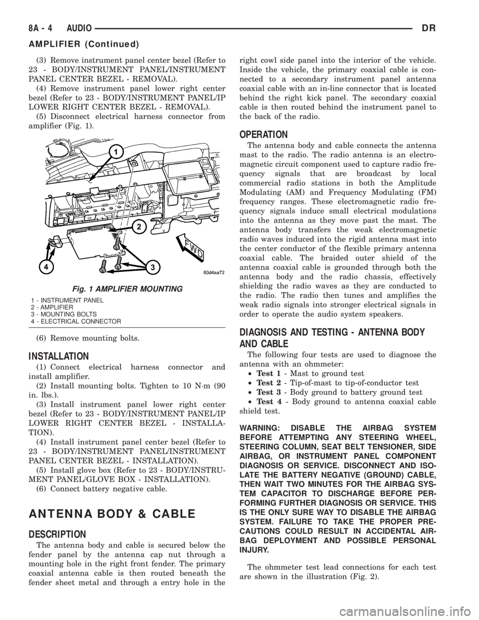
(5) Disconnect electrical harness connector from
amplifier (Fig. 1).
(6) Remove mounting bolts.
INSTALLATION
(1) Connect electrical harness connector and
install amplifier.
(2) Install mounting bolts. Tighten to 10 N´m (90
in. lbs.).
(3) Install instrument panel lower right center
bezel (Refer to 23 - BODY/INSTRUMENT PANEL/IP
LOWER RIGHT CENTER BEZEL - INSTALLA-
TION).
(4) Install instrument panel center bezel (Refer to
23 - BODY/INSTRUMENT PANEL/INSTRUMENT
PANEL CENTER BEZEL - INSTALLATION).
(5) Install glove box (Refer to 23 - BODY/INSTRU-
MENT PANEL/GLOVE BOX - INSTALLATION).
(6) Connect battery negative cable.
ANTENNA BODY & CABLE
DESCRIPTION
The antenna body and cable is secured below the
fender panel by the antenna cap nut through a
mounting hole in the right front fender. The primary
coaxial antenna cable is then routed beneath the
fender sheet metal and through a entry hole in theright cowl side panel into the interior of the vehicle.
Inside the vehicle, the primary coaxial cable is con-
nected to a secondary instrument panel antenna
coaxial cable with an in-line connector that is located
behind the right kick panel. The secondary coaxial
cable is then routed behind the instrument panel to
the back of the radio.
OPERATION
The antenna body and cable connects the antenna
mast to the radio. The radio antenna is an electro-
magnetic circuit component used to capture radio fre-
quency signals that are broadcast by local
commercial radio stations in both the Amplitude
Modulating (AM) and Frequency Modulating (FM)
frequency ranges. These electromagnetic radio fre-
quency signals induce small electrical modulations
into the antenna as they move past the mast. The
antenna body transfers the weak electromagnetic
radio waves induced into the rigid antenna mast into
the center conductor of the flexible primary antenna
coaxial cable. The braided outer shield of the
antenna coaxial cable is grounded through both the
antenna body and the radio chassis, effectively
shielding the radio waves as they are conducted to
the radio. The radio then tunes and amplifies the
weak radio signals into stronger electrical signals in
order to operate the audio system speakers.
DIAGNOSIS AND TESTING - ANTENNA BODY
AND CABLE
The following four tests are used to diagnose the
antenna with an ohmmeter:
²Test 1- Mast to ground test
²Test 2- Tip-of-mast to tip-of-conductor test
²Test 3- Body ground to battery ground test
²Test 4- Body ground to antenna coaxial cable
shield test.
WARNING: DISABLE THE AIRBAG SYSTEM
BEFORE ATTEMPTING ANY STEERING WHEEL,
STEERING COLUMN, SEAT BELT TENSIONER, SIDE
AIRBAG, OR INSTRUMENT PANEL COMPONENT
DIAGNOSIS OR SERVICE. DISCONNECT AND ISO-
LATE THE BATTERY NEGATIVE (GROUND) CABLE,
THEN WAIT TWO MINUTES FOR THE AIRBAG SYS-
TEM CAPACITOR TO DISCHARGE BEFORE PER-
FORMING FURTHER DIAGNOSIS OR SERVICE. THIS
IS THE ONLY SURE WAY TO DISABLE THE AIRBAG
SYSTEM. FAILURE TO TAKE THE PROPER PRE-
CAUTIONS COULD RESULT IN ACCIDENTAL AIR-
BAG DEPLOYMENT AND POSSIBLE PERSONAL
INJURY.
The ohmmeter test lead connections for each test
are shown in the illustration (Fig. 2).
Fig. 1 AMPLIFIER MOUNTING
1 - INSTRUMENT PANEL
2 - AMPLIFIER
3 - MOUNTING BOLTS
4 - ELECTRICAL CONNECTOR
8A - 4 AUDIODR
AMPLIFIER (Continued)
Page 369 of 2895

antenna body to fender mating surfaces and tighten
the antenna cap nut to specifications.
(4) Check the resistance again with an ohmmeter.
If the resistance is still more then one ohm, replace
the faulty antenna body and cable.
REMOVAL
(1) Disconnect and isolate the battery negative
cable.
(2) Remove the right side kick panel.
(3) Disconnect antenna body cable from instru-
ment panel cable.
(4) Securely tie a suitable length of cord or twine
to the antenna half of the coaxial cable connector.
This cord will be used to pull the cable back into
position during installation.
(5) Remove the antenna mast.
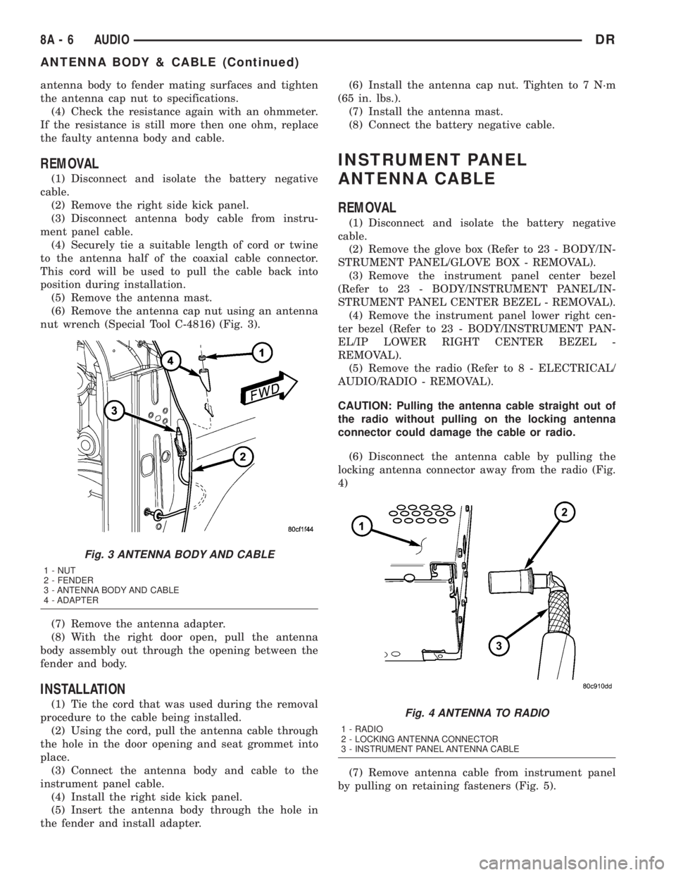
(6) Remove the antenna cap nut using an antenna
nut wrench (Special Tool C-4816) (Fig. 3).
(7) Remove the antenna adapter.
(8) With the right door open, pull the antenna
body assembly out through the opening between the
fender and body.
INSTALLATION
(1) Tie the cord that was used during the removal
procedure to the cable being installed.
(2) Using the cord, pull the antenna cable through
the hole in the door opening and seat grommet into
place.
(3) Connect the antenna body and cable to the
instrument panel cable.
(4) Install the right side kick panel.
(5) Insert the antenna body through the hole in
the fender and install adapter.(6) Install the antenna cap nut. Tighten to 7 N´m
(65 in. lbs.).
(7) Install the antenna mast.
(8) Connect the battery negative cable.
INSTRUMENT PANEL
ANTENNA CABLE
REMOVAL
(1) Disconnect and isolate the battery negative
cable.
(2) Remove the glove box (Refer to 23 - BODY/IN-
STRUMENT PANEL/GLOVE BOX - REMOVAL).
(3) Remove the instrument panel center bezel
(Refer to 23 - BODY/INSTRUMENT PANEL/IN-
STRUMENT PANEL CENTER BEZEL - REMOVAL).
(4) Remove the instrument panel lower right cen-
ter bezel (Refer to 23 - BODY/INSTRUMENT PAN-
EL/IP LOWER RIGHT CENTER BEZEL -
REMOVAL).
(5) Remove the radio (Refer to 8 - ELECTRICAL/
AUDIO/RADIO - REMOVAL).
CAUTION: Pulling the antenna cable straight out of
the radio without pulling on the locking antenna
connector could damage the cable or radio.
(6) Disconnect the antenna cable by pulling the
locking antenna connector away from the radio (Fig.
4)
(7) Remove antenna cable from instrument panel
by pulling on retaining fasteners (Fig. 5).
Fig. 3 ANTENNA BODY AND CABLE
1 - NUT
2 - FENDER
3 - ANTENNA BODY AND CABLE
4 - ADAPTER
Fig. 4 ANTENNA TO RADIO
1 - RADIO
2 - LOCKING ANTENNA CONNECTOR
3 - INSTRUMENT PANEL ANTENNA CABLE
8A - 6 AUDIODR
ANTENNA BODY & CABLE (Continued)
Page 370 of 2895

INSTALLATION
(1) Install antenna cable to instrument panel by
pressing retaining fasteners into position.
(2) Connect instrument panel antenna cable to
antenna body and cable.
(3) Install radio (Refer to 8 - ELECTRICAL/AU-
DIO/RADIO - INSTALLATION).
(4) Install the instrument panel lower right center
bezel (Refer to 23 - BODY/INSTRUMENT PANEL/IP
LOWER RIGHT CENTER BEZEL - INSTALLA-
TION).
(5) Install the instrument panel center bezel (Refer
to 23 - BODY/INSTRUMENT PANEL/INSTRUMENT
PANEL CENTER BEZEL - INSTALLATION).
(6) Install the glove box (Refer to 23 - BODY/IN-
STRUMENT PANEL/GLOVE BOX - INSTALLA-
TION).
(7) Connect the battery negative cable.
RADIO
DESCRIPTION
Available factory-installed radio receivers for this
model include:
²AM/FM/cassette with CD changer control fea-
ture (RBB sales code)
²AM/FM/cassette/CD/graphic equalizer with CD
changer control feature (RAZ sales code)
²AM/FM/CD with CD changer control feature
(RBK sales code)
²AM/FM/CD with 6 CD changer (RBQ sales code)
²AM/FM/cassette/CD (RBY sales code) - export
only
All factory-installed radio receivers can communi-
cate on the Programmable Communications Interface(PCI) data bus network. All factory-installed receiv-
ers are stereo Electronically Tuned Radios (ETR) and
include an electronic digital clock function.
These radio receivers can only be serviced by an
authorized radio repair station. See the latest War-
ranty Policies and Procedures manual for a current
listing of authorized radio repair stations.
OPERATION
The radio receiver operates on ignition switched
battery current that is available only when the igni-
tion switch is in the On or Accessory positions. The
electronic digital clock function of the radio operates
on fused battery current supplied through the IOD
fuse, regardless of the ignition switch position.
For more information on the features, setting pro-
cedures, and control functions for each of the avail-
able factory-installed radio receivers, refer to the
owner's manual.
REMOVAL
(1) Disconnect and isolate the battery negative
cable.
(2) Remove center instrument panel bezel (Refer to
23 - BODY/INSTRUMENT PANEL/INSTRUMENT
PANEL CENTER BEZEL - REMOVAL).
(3) Remove radio mounting screws (Fig. 6).
(4) Disconnect electrical harness connector.
CAUTION: Pulling the antenna cable straight out of
the radio without pulling on the locking antenna
connector could damage the cable or radio.
(5) Disconnect the antenna cable by pulling the
locking antenna connector away from the radio (Fig.
7)
Fig. 5 INSTRUMENT PANEL ANTENNA CABLE
1 - INSTRUMENT PANEL ANTENNA CABLE
2 - ANTENNA BODY AND CABLE
Fig. 6 RADIO
DRAUDIO 8A - 7
INSTRUMENT PANEL ANTENNA CABLE (Continued)
Page 375 of 2895

REMOVAL
WARNING: DISABLE THE AIRBAG SYSTEM
BEFORE ATTEMPTING ANY STEERING WHEEL,
STEERING COLUMN, SEAT BELT TENSIONER, SIDE
AIRBAG, OR INSTRUMENT PANEL COMPONENT
DIAGNOSIS OR SERVICE. DISCONNECT AND ISO-
LATE THE BATTERY NEGATIVE (GROUND) CABLE,
THEN WAIT TWO MINUTES FOR THE AIRBAG SYS-
TEM CAPACITOR TO DISCHARGE BEFORE PER-
FORMING FURTHER DIAGNOSIS OR SERVICE. THIS
IS THE ONLY SURE WAY TO DISABLE THE AIRBAG
SYSTEM. FAILURE TO TAKE THE PROPER PRE-
CAUTIONS COULD RESULT IN ACCIDENTAL AIR-
BAG DEPLOYMENT AND POSSIBLE PERSONAL
INJURY.
(1) Disconnect and isolate the battery negative
cable.
(2) Remove the driver airbag from the vehicle
(Refer to 8 - ELECTRICAL/RESTRAINTS/DRIVER
AIRBAG - REMOVAL).
(3) Remove the speed control switches (Refer to 8 -
ELECTRICAL/SPEED CONTROL/SWITCH -
REMOVAL).
(4) Unplug the wire harness connector from the
remote radio switch(es).
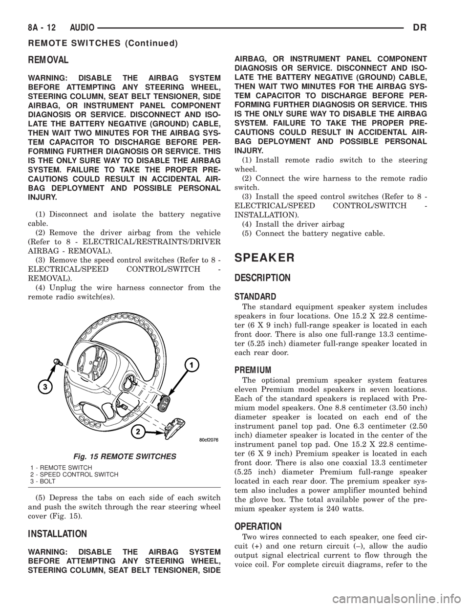
(5) Depress the tabs on each side of each switch
and push the switch through the rear steering wheel
cover (Fig. 15).
INSTALLATION
WARNING: DISABLE THE AIRBAG SYSTEM
BEFORE ATTEMPTING ANY STEERING WHEEL,
STEERING COLUMN, SEAT BELT TENSIONER, SIDEAIRBAG, OR INSTRUMENT PANEL COMPONENT
DIAGNOSIS OR SERVICE. DISCONNECT AND ISO-
LATE THE BATTERY NEGATIVE (GROUND) CABLE,
THEN WAIT TWO MINUTES FOR THE AIRBAG SYS-
TEM CAPACITOR TO DISCHARGE BEFORE PER-
FORMING FURTHER DIAGNOSIS OR SERVICE. THIS
IS THE ONLY SURE WAY TO DISABLE THE AIRBAG
SYSTEM. FAILURE TO TAKE THE PROPER PRE-
CAUTIONS COULD RESULT IN ACCIDENTAL AIR-
BAG DEPLOYMENT AND POSSIBLE PERSONAL
INJURY.
(1) Install remote radio switch to the steering
wheel.
(2) Connect the wire harness to the remote radio
switch.
(3) Install the speed control switches (Refer to 8 -
ELECTRICAL/SPEED CONTROL/SWITCH -
INSTALLATION).
(4) Install the driver airbag
(5) Connect the battery negative cable.
SPEAKER
DESCRIPTION
STANDARD
The standard equipment speaker system includes
speakers in four locations. One 15.2 X 22.8 centime-
ter (6 X 9 inch) full-range speaker is located in each
front door. There is also one full-range 13.3 centime-
ter (5.25 inch) diameter full-range speaker located in
each rear door.
PREMIUM
The optional premium speaker system features
eleven Premium model speakers in seven locations.
Each of the standard speakers is replaced with Pre-
mium model speakers. One 8.8 centimeter (3.50 inch)
diameter speaker is located on each end of the
instrument panel top pad. One 6.3 centimeter (2.50
inch) diameter speaker is located in the center of the
instrument panel top pad. One 15.2 X 22.8 centime-
ter (6 X 9 inch) Premium speaker is located in each
front door. There is also one coaxial 13.3 centimeter
(5.25 inch) diameter Premium full-range speaker
located in each rear door. The premium speaker sys-
tem also includes a power amplifier mounted behind
the glove box. The total available power of the pre-
mium speaker system is 240 watts.
OPERATION
Two wires connected to each speaker, one feed cir-
cuit (+) and one return circuit (±), allow the audio
output signal electrical current to flow through the
voice coil. For complete circuit diagrams, refer to the
Fig. 15 REMOTE SWITCHES
1 - REMOTE SWITCH
2 - SPEED CONTROL SWITCH
3 - BOLT
8A - 12 AUDIODR
REMOTE SWITCHES (Continued)
Page 407 of 2895

For battery system maintenance schedules and
jump starting procedures, see the owner's manual in
the vehicle glove box. Optionally, refer to the Lubri-
cation and Maintenance section of this manual for
the proper battery jump starting procedure. While
battery charging can be considered a maintenance
procedure, the battery charging procedure and
related information are located later in this section of
the service manual. This was done because the bat-
tery must be fully-charged before any battery system
diagnosis or testing procedures can be performed.
OPERATION
The battery system is designed to provide a safe,
efficient, reliable and mobile means of delivering and
storing electrical energy. This electrical energy is
required to operate the engine starting system, as
well as to operate many of the other vehicle acces-
sory systems for limited durations while the engine
and/or the charging system are not operating. The
battery system is also designed to provide a reserve
of electrical energy to supplement the charging sys-
tem for short durations while the engine is running
and the electrical current demands of the vehicle
exceed the output of the charging system. In addition
to delivering, and storing electrical energy for the
vehicle, the battery system serves as a capacitor and
voltage stabilizer for the vehicle electrical system. It
absorbs most abnormal or transient voltages caused
by the switching of any of the electrical components
or circuits in the vehicle.
DIAGNOSIS AND TESTING - BATTERY SYSTEM
The battery, starting, and charging systems in the
vehicle operate with one another and must be tested
as a complete system. In order for the engine to start
and the battery to maintain its charge properly, all of
the components that are used in these systems must
perform within specifications. It is important thatthe battery, starting, and charging systems be thor-
oughly tested and inspected any time a battery needs
to be charged or replaced. The cause of abnormal bat-
tery discharge, overcharging or early battery failure
must be diagnosed and corrected before a battery is
replaced and before a vehicle is returned to service.
The service information for these systems has been
separated within this service manual to make it eas-
ier to locate the specific information you are seeking.
However, when attempting to diagnose any of these
systems, it is important that you keep their interde-
pendency in mind.
The diagnostic procedures used for the battery,
starting, and charging systems include the most
basic conventional diagnostic methods, to the more
sophisticated On-Board Diagnostics (OBD) built into
the Powertrain Control Module (PCM). Use of an
induction-type milliampere ammeter, a volt/ohmme-
ter, a battery charger, a carbon pile rheostat (load
tester), a 12-volt test lamp and/or special service
tools may be required. All OBD-sensed systems are
monitored by the PCM. Each monitored circuit is
assigned a Diagnostic Trouble Code (DTC). The PCM
will store a DTC in electronic memory for any failure
it detects. Always check the PCM for stored trouble
codes before returning the vehicle to service. Refer to
Charging System for the proper charging system test
procedures. Refer to Starting System for the proper
starting system test procedures.
MICRO 420 BATTERY TESTER
The Micro 420 automotive battery tester is
designed to help the dealership technician diagnose a
defective battery. Follow the instruction manual sup-
plied with the tester to properly diagnose a battery.
If the instruction manual is not available, refer to
the standard procedure in this section, which
includes the directions for using the Micro 420 bat-
tery tester.
8F - 2 BATTERY SYSTEMDR
BATTERY SYSTEM (Continued)
Page 446 of 2895

HEATED SYSTEMS
TABLE OF CONTENTS
page page
HEATED MIRRORS......................... 1 HEATED SEATSYSTEM..................... 3
HEATED MIRRORS
TABLE OF CONTENTS
page page
HEATED MIRRORS
DESCRIPTION - HEATED MIRROR SYSTEM . . . 1
OPERATION - HEATED MIRROR SYSTEM.....1DIAGNOSIS AND TESTING - HEATED
MIRROR SYSTEM......................2
HEATED MIRRORS
DESCRIPTION - HEATED MIRROR SYSTEM
Electrically heated outside rear view mirrors are
an additional factory-installed option on models that
are equipped with factory-installed dual power mir-
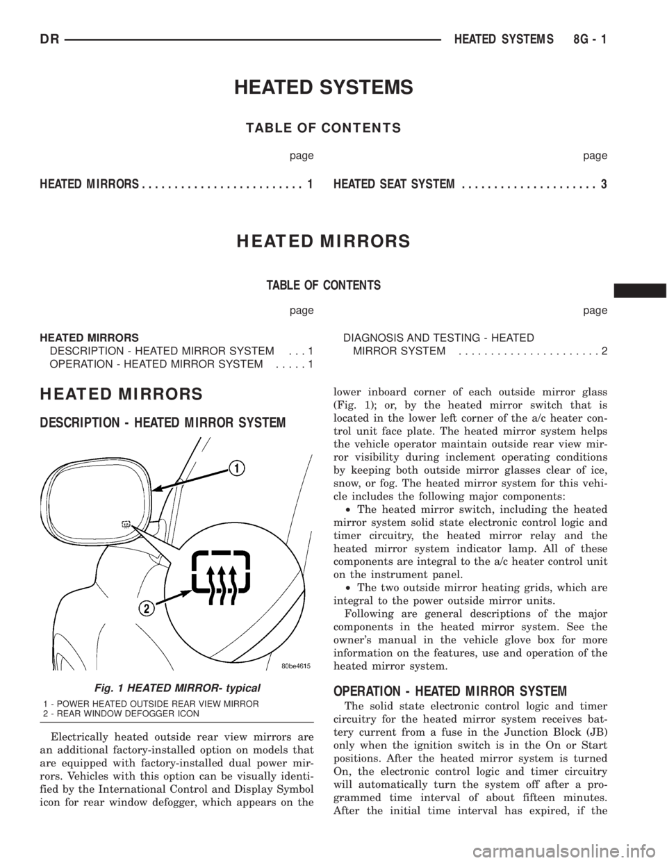
rors. Vehicles with this option can be visually identi-
fied by the International Control and Display Symbol
icon for rear window defogger, which appears on thelower inboard corner of each outside mirror glass
(Fig. 1); or, by the heated mirror switch that is
located in the lower left corner of the a/c heater con-
trol unit face plate. The heated mirror system helps
the vehicle operator maintain outside rear view mir-
ror visibility during inclement operating conditions
by keeping both outside mirror glasses clear of ice,
snow, or fog. The heated mirror system for this vehi-
cle includes the following major components:
²The heated mirror switch, including the heated
mirror system solid state electronic control logic and
timer circuitry, the heated mirror relay and the
heated mirror system indicator lamp. All of these
components are integral to the a/c heater control unit
on the instrument panel.
²The two outside mirror heating grids, which are
integral to the power outside mirror units.
Following are general descriptions of the major
components in the heated mirror system. See the
owner's manual in the vehicle glove box for more
information on the features, use and operation of the
heated mirror system.
OPERATION - HEATED MIRROR SYSTEM
The solid state electronic control logic and timer
circuitry for the heated mirror system receives bat-
tery current from a fuse in the Junction Block (JB)
only when the ignition switch is in the On or Start
positions. After the heated mirror system is turned
On, the electronic control logic and timer circuitry
will automatically turn the system off after a pro-
grammed time interval of about fifteen minutes.
After the initial time interval has expired, if the
Fig. 1 HEATED MIRROR- typical
1 - POWER HEATED OUTSIDE REAR VIEW MIRROR
2 - REAR WINDOW DEFOGGER ICON
DRHEATED SYSTEMS 8G - 1
Page 448 of 2895

HEATED SEAT SYSTEM
TABLE OF CONTENTS
page page
HEATED SEAT SYSTEM
DESCRIPTION..........................3
OPERATION............................4
DIAGNOSIS AND TESTING - HEATED SEAT
SYSTEM.............................4
HEATED SEAT ELEMENT
DESCRIPTION..........................5
OPERATION............................6
DIAGNOSIS AND TESTING - HEATED SEAT
ELEMENT............................6
REMOVAL.............................6
INSTALLATION..........................6
HEATED SEAT SENSOR
DESCRIPTION..........................7OPERATION............................7
DIAGNOSIS AND TESTING - HEATED SEAT
SENSOR.............................7
REMOVAL.............................7
HEATED SEAT SWITCH
DESCRIPTION..........................7
OPERATION............................8
DIAGNOSIS AND TESTING - HEATED SEAT
SWITCH.............................8
REMOVAL.............................9
INSTALLATION..........................9
HEATED SEAT SYSTEM
DESCRIPTION
Individually controlled, electrically heated front
seats are available as a factory-installed option on
some DR models. Vehicles with this option can be
visually identified by the leather trim seats and two
separate heated seat switches mounted in the lower
center of the instrument panel. The heated seat sys-
tem allows the front seat driver and passenger to
select from two different levels of electrical seat heat-
ing, or no seat heating to suit their individual com-
fort requirements. The heated seat system for this
vehicle includes the following major components,
which are described in further detail later in this sec-
tion:
²Heated Seat Switches- Two heated seat
switches are used per vehicle. One switch is used for
each front seat. The switches are mounted in the
instrument panel, below the radio (Fig. 1). Each
switch also includes two Light-Emitting Diode (LED)
indicator lamps and an incandescent back lighting
bulb.
²Heated Seat Module- also referred to as the
Seat Heat Interface Module (SHIM), this module con-
tains the solid state electronic control and diagnostic
logic circuitry for the heated seat system. One heated
seat module is used per vehicle and is mounted
under the drivers front seat cushion (Fig. 1). Refer to
the Electronic Control Modules section of the service
manual for additional heated seat module informa-
tion.²Heated Seat Elements- Four heated seat ele-
ments are used per vehicle. One element is used for
each front seat back and one element and sensor
assembly is used for each front seat cushion (Fig. 1).
The heating elements are integral to the individual
front seat and seat back cushions and cannot be
removed once installed at the factory. Replacement
seat heating elements are available, without having
to replace the entire seat cushion or trim cover. Refer
to the detailed procedure later in this section.
²Heated Seat Sensors- Two heated seat sen-
sors are used per vehicle. One heated seat tempera-
ture sensor is used for each front seat cushion. The
sensors are integral to the individual front seat cush-
ion heating elements (Fig. 1) and cannot be removed
once installed at the factory. Replacement seat heat-
ing elements with the sensors are available, without
having to replace the entire seat cushion or trim
cover. Refer to the detailed procedure later in this
section.
Following are general descriptions and operations
of the major components in the heated seat system.
See the owner's manual in the vehicle glove box for
more information on the features, use and operation
of the heated seat system. Refer toWiringfor the
location of complete heated seat system wiring dia-
grams.
DRHEATED SEAT SYSTEM 8G - 3