2003 DODGE RAM Bumper brackets
[x] Cancel search: Bumper bracketsPage 38 of 2895
FRONT - INDEPENDENT
FRONT SUSPENSION
DESCRIPTION
DESCRIPTION
The front suspension is designed to allow each
wheel to adapt to different road surfaces indepen-
dently. The wheels are mounted to hub/bearings
units bolted to the steering knuckle. The double-row
hub bearings are sealed and lubricated for life. The
steering knuckles turn (pivot) on ball joints.
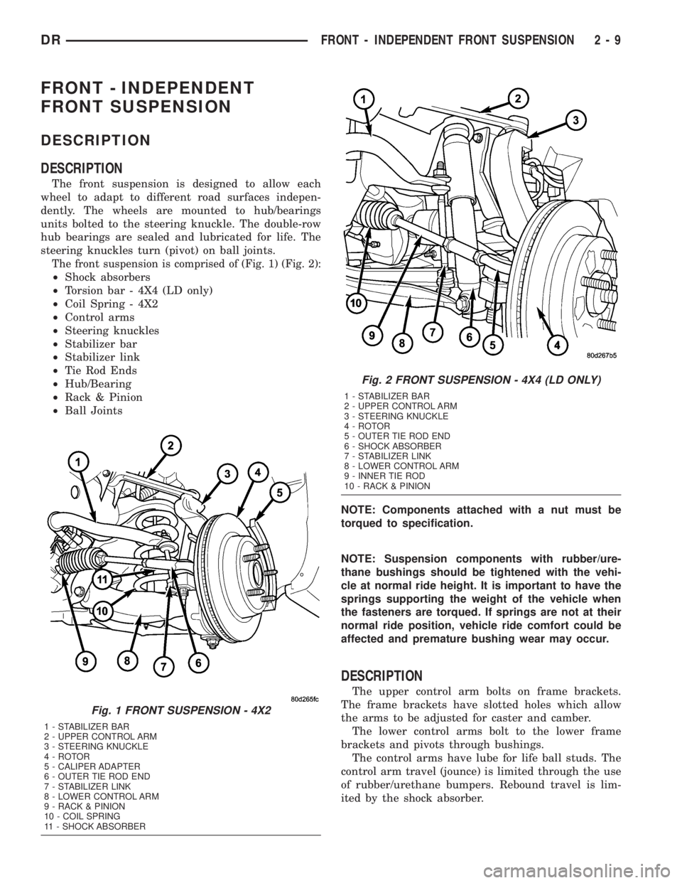
The front suspension is comprised of (Fig. 1) (Fig. 2):
²Shock absorbers
²Torsion bar - 4X4 (LD only)
²Coil Spring - 4X2
²Control arms
²Steering knuckles
²Stabilizer bar
²Stabilizer link
²Tie Rod Ends
²Hub/Bearing
²Rack & Pinion
²Ball Joints
NOTE: Components attached with a nut must be
torqued to specification.
NOTE: Suspension components with rubber/ure-
thane bushings should be tightened with the vehi-
cle at normal ride height. It is important to have the
springs supporting the weight of the vehicle when
the fasteners are torqued. If springs are not at their
normal ride position, vehicle ride comfort could be
affected and premature bushing wear may occur.
DESCRIPTION
The upper control arm bolts on frame brackets.
The frame brackets have slotted holes which allow
the arms to be adjusted for caster and camber.
The lower control arms bolt to the lower frame
brackets and pivots through bushings.
The control arms have lube for life ball studs. The
control arm travel (jounce) is limited through the use
of rubber/urethane bumpers. Rebound travel is lim-
ited by the shock absorber.
Fig. 1 FRONT SUSPENSION - 4X2
1 - STABILIZER BAR
2 - UPPER CONTROL ARM
3 - STEERING KNUCKLE
4 - ROTOR
5 - CALIPER ADAPTER
6 - OUTER TIE ROD END
7 - STABILIZER LINK
8 - LOWER CONTROL ARM
9 - RACK & PINION
10 - COIL SPRING
11 - SHOCK ABSORBER
Fig. 2 FRONT SUSPENSION - 4X4 (LD ONLY)
1 - STABILIZER BAR
2 - UPPER CONTROL ARM
3 - STEERING KNUCKLE
4 - ROTOR
5 - OUTER TIE ROD END
6 - SHOCK ABSORBER
7 - STABILIZER LINK
8 - LOWER CONTROL ARM
9 - INNER TIE ROD
10 - RACK & PINION
DRFRONT - INDEPENDENT FRONT SUSPENSION 2 - 9
Page 67 of 2895
REAR
TABLE OF CONTENTS
page page
REAR
DESCRIPTION.........................38
DIAGNOSIS AND TESTING - SPRING AND
SHOCK.............................38
SPECIFICATIONS
TORQUE CHART......................39
BUSHINGS
REMOVAL.............................39
INSTALLATION.........................39
JOUNCE BUMPER
REMOVAL.............................40
INSTALLATION.........................40
AUXILIARY SPRING BUMPERS (3500)
REMOVAL.............................40INSTALLATION.........................40
SHOCK
REMOVAL.............................40
INSTALLATION.........................40
SPRING
DESCRIPTION.........................41
OPERATION...........................41
REMOVAL.............................41
INSTALLATION.........................41
SPRING TIP INSERTS
REMOVAL.............................41
INSTALLATION.........................42
REAR
DESCRIPTION
The rear suspension is comprised of:
²Shock Absorbers
²Jounce Bumpers
²Stabilizer Bar (optional)
²Leaf Springs
²Auxiliary Leaf Spring (3500 series)
²Auxiliary Spring Bumpers (3500 series)
²Drive Axle
CAUTION: A vehicle should always be loaded so
the vehicle weight center-line is located immedi-
ately forward of the rear axle. Correct vehicle load-
ing provides proper front tire-to-road contact. This
results in maximum vehicle handling stability and
safety. Incorrect vehicle weight distribution can
cause excessive tire tread wear, spring fatigue or
failure, and erratic steering.
CAUTION: Suspension components with rubber/ure-
thane bushings (except stabilizer bar) should be
tightened with the vehicle at normal ride height. It is
important to have the springs supporting the weight
of the vehicle when the fasteners are torqued. If
springs are not at their normal ride position, vehicle
ride comfort could be affected and premature bush-
ing wear may occur.
DIAGNOSIS AND TESTING - SPRING AND
SHOCK
A knocking or rattling noise from a shock absorber
may be caused by movement between mounting
bushings and metal brackets or attaching compo-
nents. These noises can usually be stopped by tight-
ening the attaching nuts. If the noise persists,
inspect for damaged and worn bushings, and attach-
ing components. Repair as necessary if any of these
conditions exist.
A squeaking noise from the shock absorber may be
caused by the hydraulic valving and may be intermit-
tent. This condition is not repairable and the shock
absorber must be replaced.
The shock absorbers are not refillable or adjust-
able. If a malfunction occurs, the shock absorber
must be replaced. To test a shock absorber, hold it in
an upright position and force the piston in and out of
the cylinder four or five times. The action throughout
each stroke should be smooth and even.
The spring eye and shock absorber bushings do not
require any type of lubrication. Do not attempt to
stop spring bushing noise by lubricating them.
Grease and mineral oil-base lubricants will deterio-
rate the bushing rubber.
If the vehicle is used for severe, off-road operation,
the springs should be examined periodically. Check
for broken and shifted leafs, loose and missing clips,
and broken center bolts. Refer to Spring and Shock
Absorber Diagnosis chart for additional information.
2 - 38 REARDR
Page 69 of 2895
JOUNCE BUMPER
REMOVAL
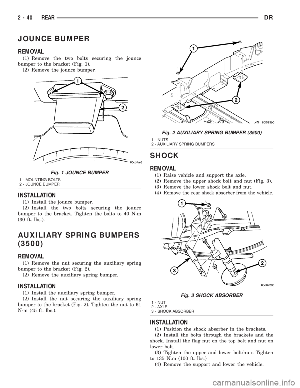
(1) Remove the two bolts securing the jounce
bumper to the bracket (Fig. 1).
(2) Remove the jounce bumper.
INSTALLATION
(1) Install the jounce bumper.
(2) Install the two bolts securing the jounce
bumper to the bracket. Tighten the bolts to 40 N´m
(30 ft. lbs.).
AUXILIARY SPRING BUMPERS
(3500)
REMOVAL
(1) Remove the nut securing the auxiliary spring
bumper to the bracket (Fig. 2).
(2) Remove the auxiliary spring bumper.
INSTALLATION
(1) Install the auxiliary spring bumper.
(2) Install the nut securing the auxiliary spring
bumper to the bracket (Fig. 2). Tighten the nut to 61
N´m (45 ft. lbs.).
SHOCK
REMOVAL
(1) Raise vehicle and support the axle.
(2) Remove the upper shock bolt and nut (Fig. 3).
(3) Remove the lower shock bolt and nut.
(4)
Remove the rear shock absorber from the vehicle.
INSTALLATION
(1) Position the shock absorber in the brackets.
(2) Install the bolts through the brackets and the
shock. Install the flag nut on the top bolt and nut on
lower bolt.
(3) Tighten the upper and lower bolt/nuts Tighten
to 135 N.m (100 ft. lbs.)
(4) Remove the support and lower the vehicle.
Fig. 1 JOUNCE BUMPER
1 - MOUNTING BOLTS
2 - JOUNCE BUMPER
Fig. 2 AUXILIARY SPRING BUMPER (3500)
1 - NUTS
2 - AUXILIARY SPRING BUMPERS
Fig. 3 SHOCK ABSORBER
1 - NUT
2 - AXLE
3 - SHOCK ABSORBER
2 - 40 REARDR
Page 1461 of 2895
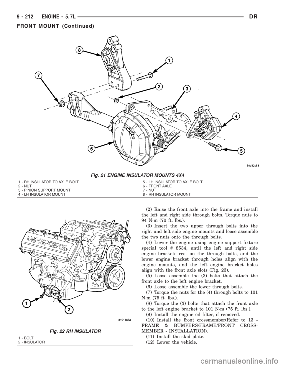
(2) Raise the front axle into the frame and install
the left and right side through bolts. Torque nuts to
94 N´m (70 ft. lbs.).
(3) Insert the two upper through bolts into the
right and left side engine mounts and loose assemble
the two nuts onto the through bolts.
(4) Lower the engine using engine support fixture
special tool # 8534, until the left and right side
engine brackets rest on the through bolts, and the
lower engine bracket through holes align with the
engine mounts, and the left engine bracket holes
align with the front axle slots (Fig. 23).
(5) Loose assemble the (3) bolts that attach the
front axle to the left engine bracket.
(6) Loose assemble the lower through bolts.
(7) Torque the nuts for the (4) through bolts to 101
N´m (75 ft. lbs.).
(8) Torque the (3) bolts that attach the front axle
to the left engine bracket to 101 N´m (75 ft. lbs.).
(9) Install the engine oil filter, if removed.
(10) Install the front crossmember(Refer to 13 -
FRAME & BUMPERS/FRAME/FRONT CROSS-
MEMBER - INSTALLATION).
(11) Install the skid plate.
(12) Lower the vehicle.
Fig. 21 ENGINE INSULATOR MOUNTS 4X4
1 - RH INSULATOR TO AXLE BOLT
2 - NUT
3 - PINION SUPPORT MOUNT
4 - LH INSULATOR MOUNT5 - LH INSULATOR TO AXLE BOLT
6 - FRONT AXLE
7 - NUT
8 - RH INSULATOR MOUNT
Fig. 22 RH INSULATOR
1 - BOLT
2 - INSULATOR
9 - 212 ENGINE - 5.7LDR
FRONT MOUNT (Continued)
Page 1673 of 2895
FRONT AIR DAM
REMOVAL
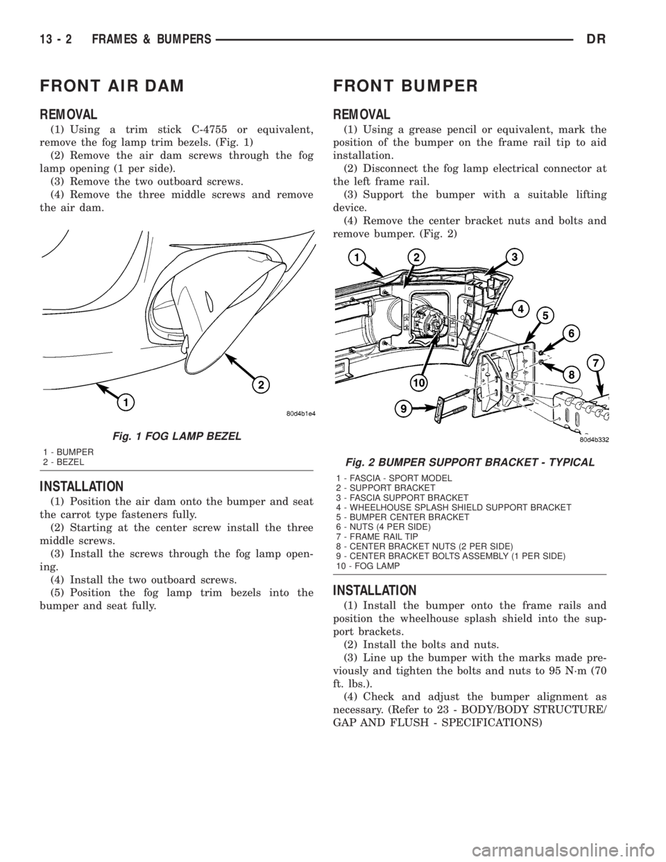
(1) Using a trim stick C-4755 or equivalent,
remove the fog lamp trim bezels. (Fig. 1)
(2) Remove the air dam screws through the fog
lamp opening (1 per side).
(3) Remove the two outboard screws.
(4) Remove the three middle screws and remove
the air dam.
INSTALLATION
(1) Position the air dam onto the bumper and seat
the carrot type fasteners fully.
(2) Starting at the center screw install the three
middle screws.
(3) Install the screws through the fog lamp open-
ing.
(4) Install the two outboard screws.
(5) Position the fog lamp trim bezels into the
bumper and seat fully.
FRONT BUMPER
REMOVAL
(1) Using a grease pencil or equivalent, mark the
position of the bumper on the frame rail tip to aid
installation.
(2) Disconnect the fog lamp electrical connector at
the left frame rail.
(3) Support the bumper with a suitable lifting
device.
(4) Remove the center bracket nuts and bolts and
remove bumper. (Fig. 2)
INSTALLATION
(1) Install the bumper onto the frame rails and
position the wheelhouse splash shield into the sup-
port brackets.
(2) Install the bolts and nuts.
(3) Line up the bumper with the marks made pre-
viously and tighten the bolts and nuts to 95 N´m (70
ft. lbs.).
(4) Check and adjust the bumper alignment as
necessary. (Refer to 23 - BODY/BODY STRUCTURE/
GAP AND FLUSH - SPECIFICATIONS)
Fig. 1 FOG LAMP BEZEL
1 - BUMPER
2 - BEZEL
Fig. 2 BUMPER SUPPORT BRACKET - TYPICAL
1 - FASCIA - SPORT MODEL
2 - SUPPORT BRACKET
3 - FASCIA SUPPORT BRACKET
4 - WHEELHOUSE SPLASH SHIELD SUPPORT BRACKET
5 - BUMPER CENTER BRACKET
6 - NUTS (4 PER SIDE)
7 - FRAME RAIL TIP
8 - CENTER BRACKET NUTS (2 PER SIDE)
9 - CENTER BRACKET BOLTS ASSEMBLY (1 PER SIDE)
10 - FOG LAMP
13 - 2 FRAMES & BUMPERSDR
Page 1675 of 2895
REAR BUMPER
REMOVAL
(1) Raise and support the vehicle. (Refer to
LUBRICATION & MAINTENANCE/HOISTING -
STANDARD PROCEDURE)
(2) Remove the license plate.
(3) Remove the bolts behind the plate.
(4) Disconnect the license plate light electrical con-
nectors.
(5) Disconnect the trailer light connector electrical
connection, if equipped.
(6) Remove the two bolts along the front upper
edge of the bumper near the frame tips.
(7)
Support the bumper with a suitable lifting device.
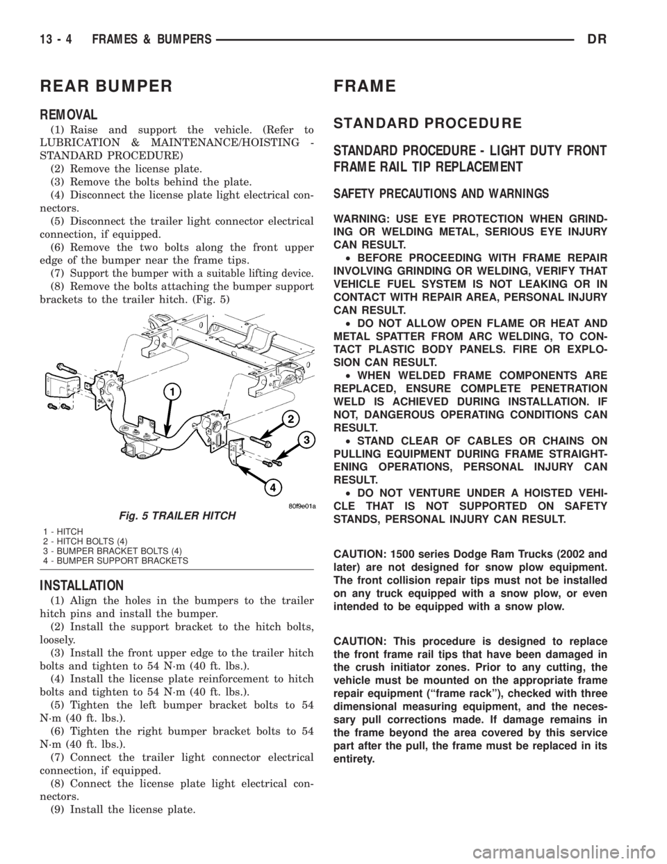
(8) Remove the bolts attaching the bumper support
brackets to the trailer hitch. (Fig. 5)
INSTALLATION
(1) Align the holes in the bumpers to the trailer
hitch pins and install the bumper.
(2) Install the support bracket to the hitch bolts,
loosely.
(3) Install the front upper edge to the trailer hitch
bolts and tighten to 54 N´m (40 ft. lbs.).
(4) Install the license plate reinforcement to hitch
bolts and tighten to 54 N´m (40 ft. lbs.).
(5) Tighten the left bumper bracket bolts to 54
N´m (40 ft. lbs.).
(6) Tighten the right bumper bracket bolts to 54
N´m (40 ft. lbs.).
(7) Connect the trailer light connector electrical
connection, if equipped.
(8) Connect the license plate light electrical con-
nectors.
(9) Install the license plate.
FRAME
STANDARD PROCEDURE
STANDARD PROCEDURE - LIGHT DUTY FRONT
FRAME RAIL TIP REPLACEMENT
SAFETY PRECAUTIONS AND WARNINGS
WARNING: USE EYE PROTECTION WHEN GRIND-
ING OR WELDING METAL, SERIOUS EYE INJURY
CAN RESULT.
²BEFORE PROCEEDING WITH FRAME REPAIR
INVOLVING GRINDING OR WELDING, VERIFY THAT
VEHICLE FUEL SYSTEM IS NOT LEAKING OR IN
CONTACT WITH REPAIR AREA, PERSONAL INJURY
CAN RESULT.
²DO NOT ALLOW OPEN FLAME OR HEAT AND
METAL SPATTER FROM ARC WELDING, TO CON-
TACT PLASTIC BODY PANELS. FIRE OR EXPLO-
SION CAN RESULT.
²WHEN WELDED FRAME COMPONENTS ARE
REPLACED, ENSURE COMPLETE PENETRATION
WELD IS ACHIEVED DURING INSTALLATION. IF
NOT, DANGEROUS OPERATING CONDITIONS CAN
RESULT.
²STAND CLEAR OF CABLES OR CHAINS ON
PULLING EQUIPMENT DURING FRAME STRAIGHT-
ENING OPERATIONS, PERSONAL INJURY CAN
RESULT.
²DO NOT VENTURE UNDER A HOISTED VEHI-
CLE THAT IS NOT SUPPORTED ON SAFETY
STANDS, PERSONAL INJURY CAN RESULT.
CAUTION: 1500 series Dodge Ram Trucks (2002 and
later) are not designed for snow plow equipment.
The front collision repair tips must not be installed
on any truck equipped with a snow plow, or even
intended to be equipped with a snow plow.
CAUTION: This procedure is designed to replace
the front frame rail tips that have been damaged in
the crush initiator zones. Prior to any cutting, the
vehicle must be mounted on the appropriate frame
repair equipment (ªframe rackº), checked with three
dimensional measuring equipment, and the neces-
sary pull corrections made. If damage remains in
the frame beyond the area covered by this service
part after the pull, the frame must be replaced in its
entirety.
Fig. 5 TRAILER HITCH
1 - HITCH
2 - HITCH BOLTS (4)
3 - BUMPER BRACKET BOLTS (4)
4 - BUMPER SUPPORT BRACKETS
13 - 4 FRAMES & BUMPERSDR
Page 1676 of 2895
CAUTION: Do not reuse damaged fasteners, quality
of repair would be suspect. Failure to use only pro-
duction fasteners or fasteners of equivalent hard-
ness can result in loosening or failure. Do not drill
any holes in the frame that are not specifically out-
lined in this or other, DaimlerChrysler procedure as
frame rail failure can result. When using heat to
straighten frame components do not exceed 566ÉC
(1050ÉF), metal fatigue can result.
NOTE: Procedures for 4X2 and 4X4 are common
except as noted in this procedure.
(1) Disconnect and isolate the battery negative
cable.
(2) Remove the front wheelhouse splash shield.
(Refer to 23 - BODY/EXTERIOR/FRONT WHEEL-
HOUSE SPLASH SHIELD - REMOVAL)
(3) Remove the bolts and position aside the wire
harness and grounds, if required.
(4) Remove the front bumper. (Refer to 13 -
FRAME & BUMPERS/BUMPERS/FRONT BUMPER
- REMOVAL)
(5) Loosen and lower the stabilizer bar mount and
bar. (Refer to 2 - SUSPENSION/FRONT/STABI-
LIZER BAR - REMOVAL)
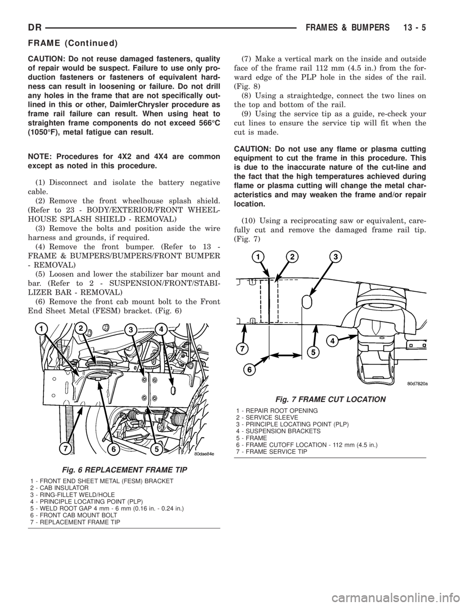
(6) Remove the front cab mount bolt to the Front
End Sheet Metal (FESM) bracket. (Fig. 6)(7) Make a vertical mark on the inside and outside
face of the frame rail 112 mm (4.5 in.) from the for-
ward edge of the PLP hole in the sides of the rail.
(Fig. 8)
(8) Using a straightedge, connect the two lines on
the top and bottom of the rail.
(9) Using the service tip as a guide, re-check your
cut lines to ensure the service tip will fit when the
cut is made.
CAUTION: Do not use any flame or plasma cutting
equipment to cut the frame in this procedure. This
is due to the inaccurate nature of the cut-line and
the fact that the high temperatures achieved during
flame or plasma cutting will change the metal char-
acteristics and may weaken the frame and/or repair
location.
(10) Using a reciprocating saw or equivalent, care-
fully cut and remove the damaged frame rail tip.
(Fig. 7)
Fig. 6 REPLACEMENT FRAME TIP
1 - FRONT END SHEET METAL (FESM) BRACKET
2 - CAB INSULATOR
3 - RING-FILLET WELD/HOLE
4 - PRINCIPLE LOCATING POINT (PLP)
5 - WELD ROOT GAP 4 mm-6mm(0.16 in. - 0.24 in.)
6 - FRONT CAB MOUNT BOLT
7 - REPLACEMENT FRAME TIP
Fig. 7 FRAME CUT LOCATION
1 - REPAIR ROOT OPENING
2 - SERVICE SLEEVE
3 - PRINCIPLE LOCATING POINT (PLP)
4 - SUSPENSION BRACKETS
5 - FRAME
6 - FRAME CUTOFF LOCATION - 112 mm (4.5 in.)
7 - FRAME SERVICE TIP
DRFRAMES & BUMPERS 13 - 5
FRAME (Continued)
Page 1696 of 2895
INSTALLATION
(1) Install the crossmember and install the bolts.
(2) Tighten the bolts to 102 N´m (75 ft. lbs.).
(3) Install the transmission mount nuts and
tighten to 61 N´m (45 ft. lbs.).
(4) Remove the transmission support.
(5) Install the transfercase skid plate. (Refer to 13
- FRAME & BUMPERS/FRAME/TRANSFER CASE
SKID PLATE - INSTALLATION)
TRAILER HITCH
REMOVAL
(1) Remove the rear bumper. (Refer to 13 -
FRAME & BUMPERS/BUMPERS/REAR BUMPER -
REMOVAL)
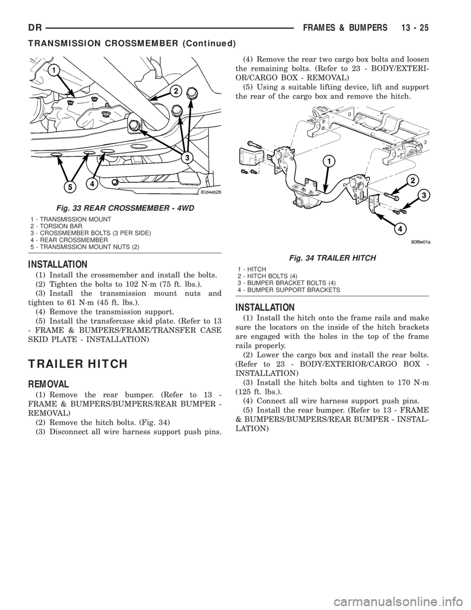
(2) Remove the hitch bolts. (Fig. 34)
(3) Disconnect all wire harness support push pins.(4) Remove the rear two cargo box bolts and loosen
the remaining bolts. (Refer to 23 - BODY/EXTERI-
OR/CARGO BOX - REMOVAL)
(5) Using a suitable lifting device, lift and support
the rear of the cargo box and remove the hitch.
INSTALLATION
(1) Install the hitch onto the frame rails and make
sure the locators on the inside of the hitch brackets
are engaged with the holes in the top of the frame
rails properly.
(2) Lower the cargo box and install the rear bolts.
(Refer to 23 - BODY/EXTERIOR/CARGO BOX -
INSTALLATION)
(3) Install the hitch bolts and tighten to 170 N´m
(125 ft. lbs.).
(4) Connect all wire harness support push pins.
(5) Install the rear bumper. (Refer to 13 - FRAME
& BUMPERS/BUMPERS/REAR BUMPER - INSTAL-
LATION)
Fig. 33 REAR CROSSMEMBER - 4WD
1 - TRANSMISSION MOUNT
2 - TORSION BAR
3 - CROSSMEMBER BOLTS (3 PER SIDE)
4 - REAR CROSSMEMBER
5 - TRANSMISSION MOUNT NUTS (2)
Fig. 34 TRAILER HITCH
1 - HITCH
2 - HITCH BOLTS (4)
3 - BUMPER BRACKET BOLTS (4)
4 - BUMPER SUPPORT BRACKETS
DRFRAMES & BUMPERS 13 - 25
TRANSMISSION CROSSMEMBER (Continued)