2003 DODGE RAM drain bolt
[x] Cancel search: drain boltPage 134 of 2895
ments, until pinion rotating torque is 0.40-0.57 N´m
(3-5 in. lbs.) greater than recorded measurement.
(8) Rotate pinion several times then verify pinion
rotating torque again.
(9) Install axle shafts and hub bearings.
(10) Install propeller shaft with reference marks
aligned.
DIFFERENTIAL
DESCRIPTION
The differential case is a one-piece design. The dif-
ferential pinion shaft is retained with a snap ring.
Differential bearing preload and ring gear backlash
is adjusted by the use of adjusters. The adjuster are
between the differential bearings and the differential
housing. Pinion bearing preload is set and main-
tained by the use of a collapsible spacer. The
stamped steel cover provides a means for inspection
and servicing the differential.
OPERATION
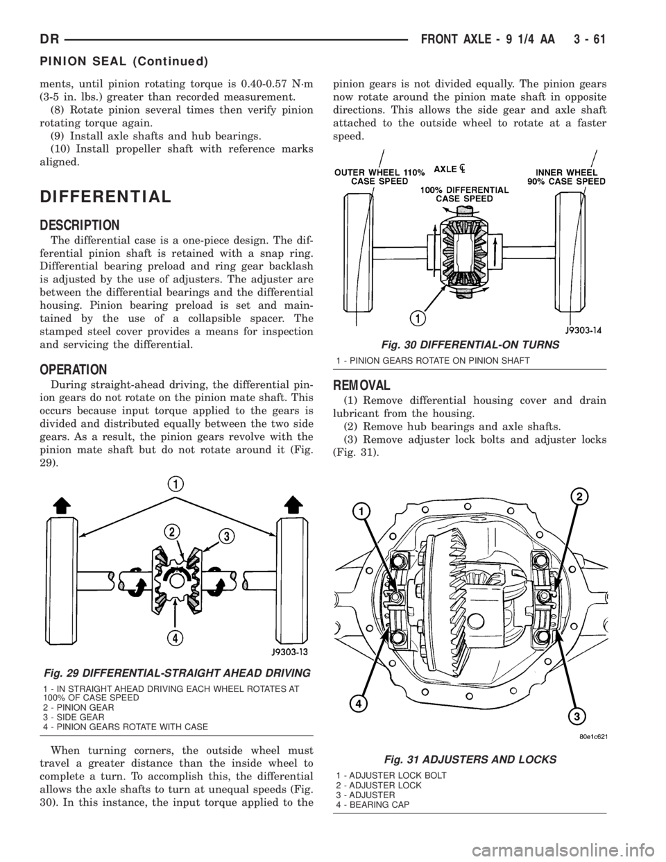
During straight-ahead driving, the differential pin-
ion gears do not rotate on the pinion mate shaft. This
occurs because input torque applied to the gears is
divided and distributed equally between the two side
gears. As a result, the pinion gears revolve with the
pinion mate shaft but do not rotate around it (Fig.
29).
When turning corners, the outside wheel must
travel a greater distance than the inside wheel to
complete a turn. To accomplish this, the differential
allows the axle shafts to turn at unequal speeds (Fig.
30). In this instance, the input torque applied to thepinion gears is not divided equally. The pinion gears
now rotate around the pinion mate shaft in opposite
directions. This allows the side gear and axle shaft
attached to the outside wheel to rotate at a faster
speed.REMOVAL
(1) Remove differential housing cover and drain
lubricant from the housing.
(2) Remove hub bearings and axle shafts.
(3) Remove adjuster lock bolts and adjuster locks
(Fig. 31).
Fig. 29 DIFFERENTIAL-STRAIGHT AHEAD DRIVING
1 - IN STRAIGHT AHEAD DRIVING EACH WHEEL ROTATES AT
100% OF CASE SPEED
2 - PINION GEAR
3 - SIDE GEAR
4 - PINION GEARS ROTATE WITH CASE
Fig. 30 DIFFERENTIAL-ON TURNS
1 - PINION GEARS ROTATE ON PINION SHAFT
Fig. 31 ADJUSTERS AND LOCKS
1 - ADJUSTER LOCK BOLT
2 - ADJUSTER LOCK
3 - ADJUSTER
4 - BEARING CAP
DRFRONT AXLE - 9 1/4 AA 3 - 61
PINION SEAL (Continued)
Page 146 of 2895
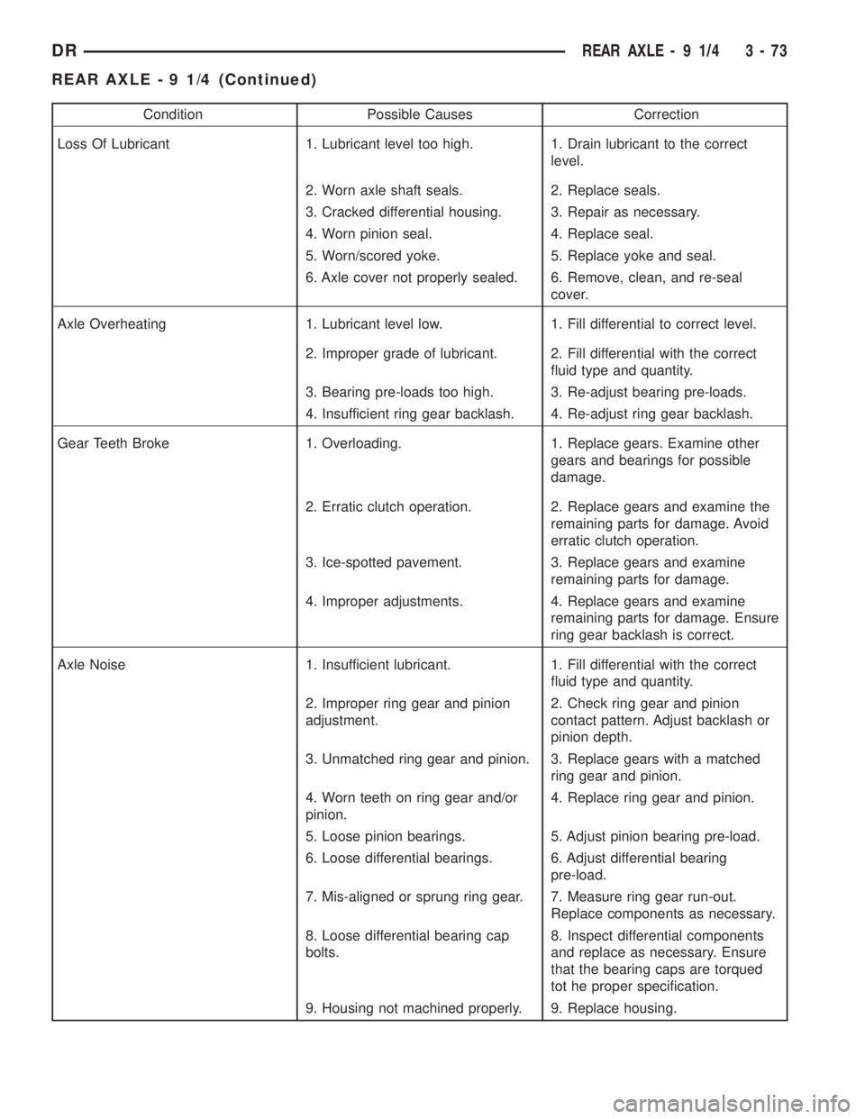
Condition Possible Causes Correction
Loss Of Lubricant 1. Lubricant level too high. 1. Drain lubricant to the correct
level.
2. Worn axle shaft seals. 2. Replace seals.
3. Cracked differential housing. 3. Repair as necessary.
4. Worn pinion seal. 4. Replace seal.
5. Worn/scored yoke. 5. Replace yoke and seal.
6. Axle cover not properly sealed. 6. Remove, clean, and re-seal
cover.
Axle Overheating 1. Lubricant level low. 1. Fill differential to correct level.
2. Improper grade of lubricant. 2. Fill differential with the correct
fluid type and quantity.
3. Bearing pre-loads too high. 3. Re-adjust bearing pre-loads.
4. Insufficient ring gear backlash. 4. Re-adjust ring gear backlash.
Gear Teeth Broke 1. Overloading. 1. Replace gears. Examine other
gears and bearings for possible
damage.
2. Erratic clutch operation. 2. Replace gears and examine the
remaining parts for damage. Avoid
erratic clutch operation.
3. Ice-spotted pavement. 3. Replace gears and examine
remaining parts for damage.
4. Improper adjustments. 4. Replace gears and examine
remaining parts for damage. Ensure
ring gear backlash is correct.
Axle Noise 1. Insufficient lubricant. 1. Fill differential with the correct
fluid type and quantity.
2. Improper ring gear and pinion
adjustment.2. Check ring gear and pinion
contact pattern. Adjust backlash or
pinion depth.
3. Unmatched ring gear and pinion. 3. Replace gears with a matched
ring gear and pinion.
4. Worn teeth on ring gear and/or
pinion.4. Replace ring gear and pinion.
5. Loose pinion bearings. 5. Adjust pinion bearing pre-load.
6. Loose differential bearings. 6. Adjust differential bearing
pre-load.
7. Mis-aligned or sprung ring gear. 7. Measure ring gear run-out.
Replace components as necessary.
8. Loose differential bearing cap
bolts.8. Inspect differential components
and replace as necessary. Ensure
that the bearing caps are torqued
tot he proper specification.
9. Housing not machined properly. 9. Replace housing.
DRREAR AXLE - 9 1/4 3 - 73
REAR AXLE - 9 1/4 (Continued)
Page 160 of 2895

(2) Remove differential cover and drain the lubri-
cant.
(3) Clean housing cavity with flushing oil, light
engine oil or a lint free cloth.
NOTE: Do not use steam, kerosene or gasoline to
clean the housing.
(4) Remove axle shafts.
(5) Remove RWAL/ABS sensor from housing.
NOTE: Side play resulting from bearing races being
loose on case hubs requires replacement of the dif-
ferential case.
(6) Mark differential housing and bearing caps for
installation reference (Fig. 30).(7) Remove bearing threaded adjuster lock from
each bearing cap.
(8) Loosen differential bearing cap bolts.
(9) Loosen differential bearing adjusters through
the axle tubes with Wrench C-4164 (Fig. 31).
(10) Hold differential case while removing bearing
caps and adjusters.
(11) Remove differential case.
NOTE: Tag the differential bearing cups and
threaded adjusters to indicate their location.
Fig. 28 DIFFERENTIAL-STRAIGHT AHEAD DRIVING
1 - IN STRAIGHT AHEAD DRIVING EACH WHEEL ROTATES AT
100% OF CASE SPEED
2 - PINION GEAR
3 - SIDE GEAR
4 - PINION GEARS ROTATE WITH CASE
Fig. 29 DIFFERENTIAL-ON TURNS
1 - PINION GEARS ROTATE ON PINION SHAFT
Fig. 30 REFERENCE MARKS
1 - REFERENCE MARKS
2 - REFERENCE MARK
3 - BEARING CAPS
Fig. 31 THREADED ADJUSTER TOOL
1 - AXLE TUBE
2 - BACKING PLATE
3 - THREAD ADJUSTER WRENCH
DRREAR AXLE - 9 1/4 3 - 87
DIFFERENTIAL (Continued)
Page 162 of 2895
CAUTION: If cover is not installed within 3 to 5 min-
utes, the cover must be cleaned and new RTV
applied or adhesion quality will be compromised.
(8) Install the cover and any identification tag and
tighten cover bolts to 41 N´m (30 ft. lbs.).
(9) Fill differential with lubricant to bottom of the
fill plug hole. Refer to the Lubricant Specifications
for the correct quantity and type.
NOTE: Trac-lokŸ differential equipped vehicles
should be road tested by making 10 to 12 slow fig-
ure-eight turns. This maneuver will pump the lubri-
cant through the clutch discs to eliminate a
possible chatter noise complaint.
DIFFERENTIAL-TRAC-LOK
DESCRIPTION
The optional Trac-Loktdifferential case has a one-
piece design and the similar internal components as
a standard differential, plus two clutch disc pack-
s.The differential pinion mate shaft is retained with
a threaded pin. Differential bearing preload and ring
gear backlash are set and maintained by threaded
adjusters at the outside of the differential housing.
Pinion bearing preload is set and maintained by the
use of a collapsible spacer. The removable differential
cover provides a means for inspection and service.
OPERATION
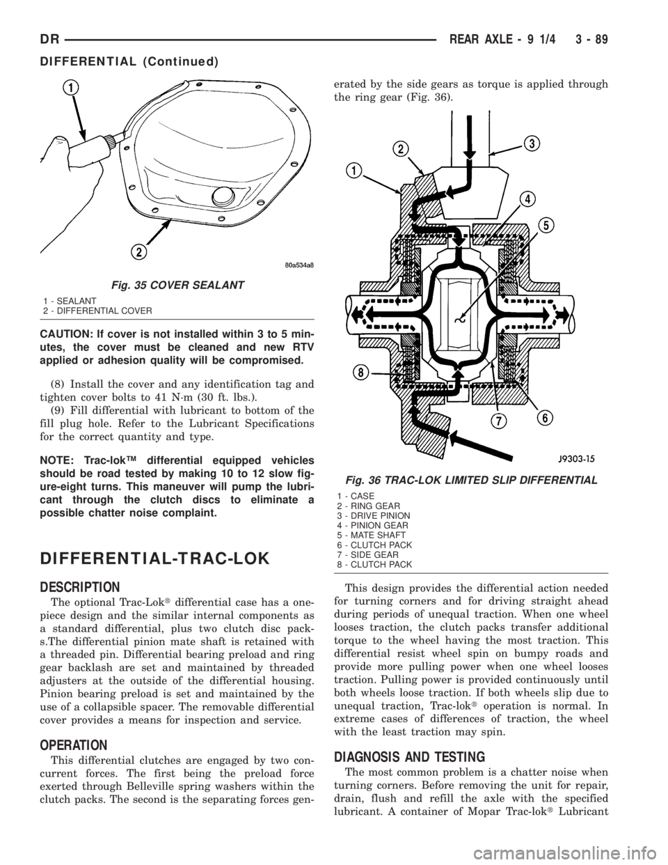
This differential clutches are engaged by two con-
current forces. The first being the preload force
exerted through Belleville spring washers within the
clutch packs. The second is the separating forces gen-erated by the side gears as torque is applied through
the ring gear (Fig. 36).
This design provides the differential action needed
for turning corners and for driving straight ahead
during periods of unequal traction. When one wheel
looses traction, the clutch packs transfer additional
torque to the wheel having the most traction. This
differential resist wheel spin on bumpy roads and
provide more pulling power when one wheel looses
traction. Pulling power is provided continuously until
both wheels loose traction. If both wheels slip due to
unequal traction, Trac-loktoperation is normal. In
extreme cases of differences of traction, the wheel
with the least traction may spin.DIAGNOSIS AND TESTING
The most common problem is a chatter noise when
turning corners. Before removing the unit for repair,
drain, flush and refill the axle with the specified
lubricant. A container of Mopar Trac-loktLubricant
Fig. 35 COVER SEALANT
1 - SEALANT
2 - DIFFERENTIAL COVER
Fig. 36 TRAC-LOK LIMITED SLIP DIFFERENTIAL
1 - CASE
2 - RING GEAR
3 - DRIVE PINION
4 - PINION GEAR
5 - MATE SHAFT
6 - CLUTCH PACK
7 - SIDE GEAR
8 - CLUTCH PACK
DRREAR AXLE - 9 1/4 3 - 89
DIFFERENTIAL (Continued)
Page 188 of 2895
REMOVAL
(1) Remove lubricant fill hole plug from the differ-
ential housing cover.
(2) Remove differential housing cover and drain
the lubricant from housing.
(3) Remove axle shafts.
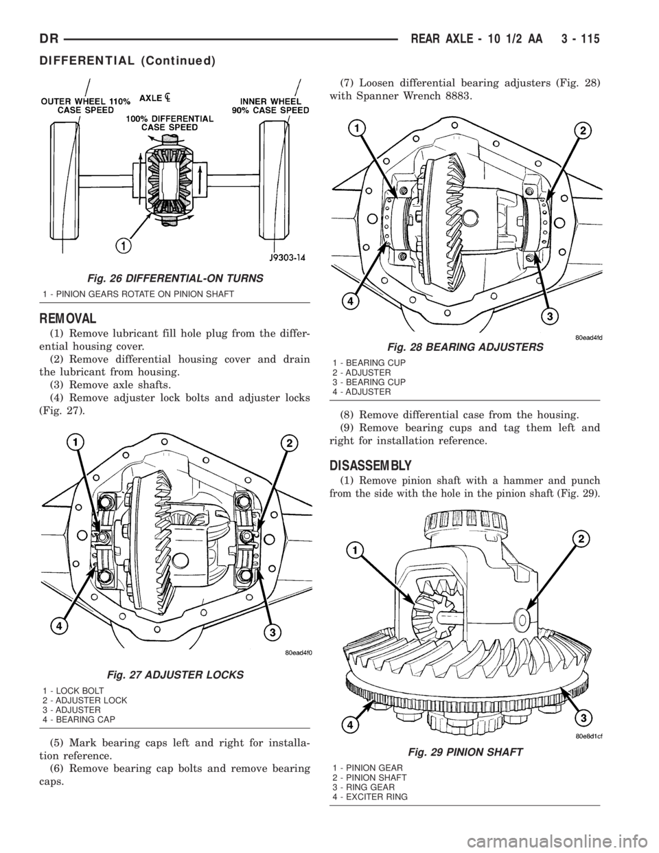
(4) Remove adjuster lock bolts and adjuster locks
(Fig. 27).
(5) Mark bearing caps left and right for installa-
tion reference.
(6) Remove bearing cap bolts and remove bearing
caps.(7) Loosen differential bearing adjusters (Fig. 28)
with Spanner Wrench 8883.
(8) Remove differential case from the housing.
(9) Remove bearing cups and tag them left and
right for installation reference.
DISASSEMBLY
(1)Remove pinion shaft with a hammer and punch
from the side with the hole in the pinion shaft (Fig. 29).
Fig. 26 DIFFERENTIAL-ON TURNS
1 - PINION GEARS ROTATE ON PINION SHAFT
Fig. 27 ADJUSTER LOCKS
1 - LOCK BOLT
2 - ADJUSTER LOCK
3 - ADJUSTER
4 - BEARING CAP
Fig. 28 BEARING ADJUSTERS
1 - BEARING CUP
2 - ADJUSTER
3 - BEARING CUP
4 - ADJUSTER
Fig. 29 PINION SHAFT
1 - PINION GEAR
2 - PINION SHAFT
3 - RING GEAR
4 - EXCITER RING
DRREAR AXLE - 10 1/2 AA 3 - 115
DIFFERENTIAL (Continued)
Page 215 of 2895
REMOVAL
(1) Remove fill hole plug from the differential
housing cover.
(2) Remove differential housing cover and drain
the lubricant.
(3) Remove axle shafts.
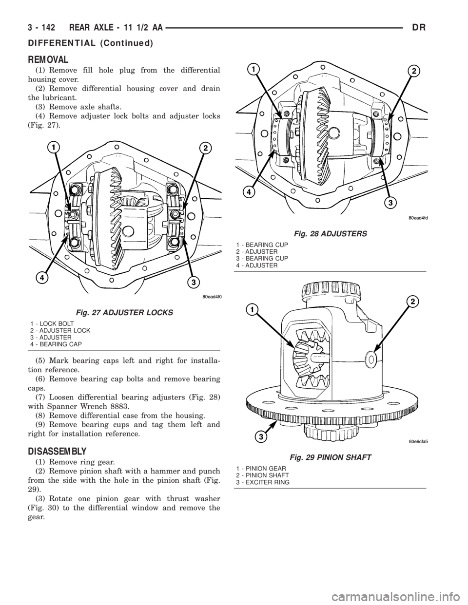
(4) Remove adjuster lock bolts and adjuster locks
(Fig. 27).
(5) Mark bearing caps left and right for installa-
tion reference.
(6) Remove bearing cap bolts and remove bearing
caps.
(7) Loosen differential bearing adjusters (Fig. 28)
with Spanner Wrench 8883.
(8) Remove differential case from the housing.
(9) Remove bearing cups and tag them left and
right for installation reference.
DISASSEMBLY
(1) Remove ring gear.
(2) Remove pinion shaft with a hammer and punch
from the side with the hole in the pinion shaft (Fig.
29).
(3) Rotate one pinion gear with thrust washer
(Fig. 30) to the differential window and remove the
gear.
Fig. 27 ADJUSTER LOCKS
1 - LOCK BOLT
2 - ADJUSTER LOCK
3 - ADJUSTER
4 - BEARING CAP
Fig. 28 ADJUSTERS
1 - BEARING CUP
2 - ADJUSTER
3 - BEARING CUP
4 - ADJUSTER
Fig. 29 PINION SHAFT
1 - PINION GEAR
2 - PINION SHAFT
3 - EXCITER RING
3 - 142 REAR AXLE - 11 1/2 AADR
DIFFERENTIAL (Continued)
Page 239 of 2895
OPERATION
When the brakes are applied fluid pressure is
exerted against the caliper piston. The fluid pressure
is exerted equally and in all directions. This means
pressure exerted against the caliper piston and
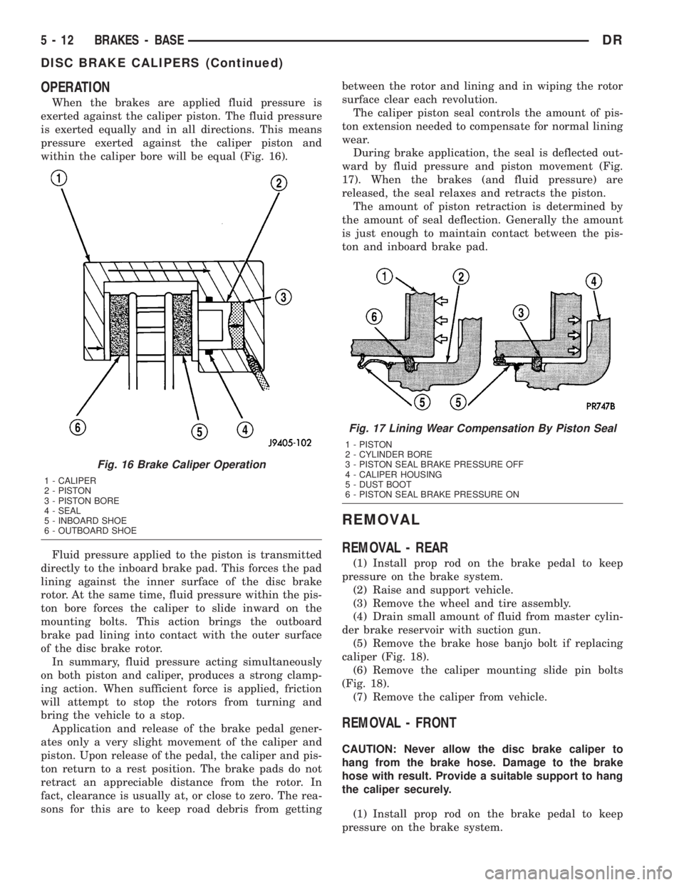
within the caliper bore will be equal (Fig. 16).
Fluid pressure applied to the piston is transmitted
directly to the inboard brake pad. This forces the pad
lining against the inner surface of the disc brake
rotor. At the same time, fluid pressure within the pis-
ton bore forces the caliper to slide inward on the
mounting bolts. This action brings the outboard
brake pad lining into contact with the outer surface
of the disc brake rotor.
In summary, fluid pressure acting simultaneously
on both piston and caliper, produces a strong clamp-
ing action. When sufficient force is applied, friction
will attempt to stop the rotors from turning and
bring the vehicle to a stop.
Application and release of the brake pedal gener-
ates only a very slight movement of the caliper and
piston. Upon release of the pedal, the caliper and pis-
ton return to a rest position. The brake pads do not
retract an appreciable distance from the rotor. In
fact, clearance is usually at, or close to zero. The rea-
sons for this are to keep road debris from gettingbetween the rotor and lining and in wiping the rotor
surface clear each revolution.
The caliper piston seal controls the amount of pis-
ton extension needed to compensate for normal lining
wear.
During brake application, the seal is deflected out-
ward by fluid pressure and piston movement (Fig.
17). When the brakes (and fluid pressure) are
released, the seal relaxes and retracts the piston.
The amount of piston retraction is determined by
the amount of seal deflection. Generally the amount
is just enough to maintain contact between the pis-
ton and inboard brake pad.
REMOVAL
REMOVAL - REAR
(1) Install prop rod on the brake pedal to keep
pressure on the brake system.
(2) Raise and support vehicle.
(3) Remove the wheel and tire assembly.
(4) Drain small amount of fluid from master cylin-
der brake reservoir with suction gun.
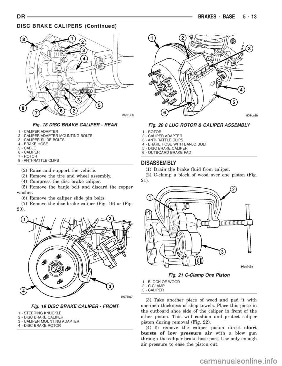
(5) Remove the brake hose banjo bolt if replacing
caliper (Fig. 18).
(6) Remove the caliper mounting slide pin bolts
(Fig. 18).
(7) Remove the caliper from vehicle.
REMOVAL - FRONT
CAUTION: Never allow the disc brake caliper to
hang from the brake hose. Damage to the brake
hose with result. Provide a suitable support to hang
the caliper securely.
(1) Install prop rod on the brake pedal to keep
pressure on the brake system.
Fig. 16 Brake Caliper Operation
1 - CALIPER
2 - PISTON
3 - PISTON BORE
4 - SEAL
5 - INBOARD SHOE
6 - OUTBOARD SHOE
Fig. 17 Lining Wear Compensation By Piston Seal
1 - PISTON
2 - CYLINDER BORE
3 - PISTON SEAL BRAKE PRESSURE OFF
4 - CALIPER HOUSING
5 - DUST BOOT
6 - PISTON SEAL BRAKE PRESSURE ON
5 - 12 BRAKES - BASEDR
DISC BRAKE CALIPERS (Continued)
Page 240 of 2895
(2) Raise and support the vehicle.
(3) Remove the tire and wheel assembly.
(4) Compress the disc brake caliper.
(5) Remove the banjo bolt and discard the copper
washer.
(6) Remove the caliper slide pin bolts.
(7) Remove the disc brake caliper (Fig. 19) or (Fig.
20).
DISASSEMBLY
(1) Drain the brake fluid from caliper.
(2) C-clamp a block of wood over one piston (Fig.
21).
(3) Take another piece of wood and pad it with
one-inch thickness of shop towels. Place this piece in
the outboard shoe side of the caliper in front of the
other piston. This will cushion and protect caliper
piston during removal (Fig. 22).
(4) To remove the caliper piston directshort
bursts of low pressure airwith a blow gun
through the caliper brake hose port. Use only enough
air pressure to ease the piston out.
Fig. 18 DISC BRAKE CALIPER - REAR
1 - CALIPER ADAPTER
2 - CALIPER ADAPTER MOUNTING BOLTS
3 - CALIPER SLIDE BOLTS
4 - BRAKE HOSE
5 - CABLE
6 - CALIPER
7 - ROTOR
8 - ANTI-RATTLE CLIPS
Fig. 19 DISC BRAKE CALIPER - FRONT
1 - STEERING KNUCKLE
2 - DISC BRAKE CALIPER
3 - CALIPER MOUNTING ADAPTER
4 - DISC BRAKE ROTOR
Fig. 20 8 LUG ROTOR & CALIPER ASSEMBLY
1 - ROTOR
2 - CALIPER ADAPTER
3 - ANTI-RATTLE CLIPS
4 - BRAKE HOSE WITH BANJO BOLT
5 - DISC BRAKE CALIPER
6 - OUTBOARD BRAKE PAD
Fig. 21 C-Clamp One Piston
1 - BLOCK OF WOOD
2 - C-CLAMP
3 - CALIPER
DRBRAKES - BASE 5 - 13
DISC BRAKE CALIPERS (Continued)