2003 DODGE RAM engine oil pan
[x] Cancel search: engine oil panPage 7 of 2895

INTERNATIONAL VEHICLE
CONTROL & DISPLAY
SYMBOLS
DESCRIPTION - INTERNATIONAL SYMBOLS
The graphic symbols illustrated in the following
International Control and Display Symbols Chart are
used to identify various instrument controls. The
symbols correspond to the controls and displays that
are located on the instrument panel.
FASTENER IDENTIFICATION
DESCRIPTION
The SAE bolt strength grades range from grade 2
to grade 8. The higher the grade number, the greater
the bolt strength. Identification is determined by the
line marks on the top of each bolt head. The actual
bolt strength grade corresponds to the number of line
marks plus 2. The most commonly used metric bolt
strength classes are 9.8 and 10.9. The metric
strength class identification number is imprinted on
the head of the bolt. The higher the class number,
the greater the bolt strength. Some metric nuts are
imprinted with a single-digit strength class on the
nut face. Refer to the Fastener Identification and
Fastener Strength Charts (Fig. 6) and (Fig. 7).
INTERNATIONAL SYMBOLS
1 High Beam 13 Rear Window Washer
2 Fog Lamps 14 Fuel
3 Headlamp, Parking Lamps, Panel Lamps 15 Engine Coolant Temperature
4 Turn Warning 16 Battery Charging Condition
5 Hazard Warning 17 Engine Oil
6 Windshield Washer 18 Seat Belt
7 Windshield Wiper 19 Brake Failure
8 Windshield Wiper and Washer 20 Parking Brake
9 Windscreen Demisting and Defrosting 21 Front Hood
10 Ventilating Fan 22 Rear hood (Decklid)
11 Rear Window Defogger 23 Horn
12 Rear Window Wiper 24 Lighter
6 INTRODUCTIONDR
Page 27 of 2895

HOISTING
STANDARD PROCEDURE - HOISTING
Refer to the Owner's Manual for emergency vehicle
lifting procedures.
WARNING: THE HOISTING AND JACK LIFTING
POINTS PROVIDED ARE FOR A COMPLETE VEHI-
CLE. WHEN A CHASSIS OR DRIVETRAIN COMPO-
NENT IS REMOVED FROM A VEHICLE, THE
CENTER OF GRAVITY IS ALTERED MAKING SOME
HOISTING CONDITIONS UNSTABLE. PROPERLY
SUPPORT (Fig. 5) OR SECURE VEHICLE TO HOIST-
ING DEVICE WHEN THESE CONDITIONS EXIST.
FLOOR JACK
When properly positioned, a floor jack can be used
to lift a vehicle (Fig. 6). Support the vehicle in the
raised position with jack stands at the front and rear
ends of the frame rails (Fig. 5).
CAUTION: Do not lift vehicle with a floor jack posi-
tioned under:
²An axle tube.
²A body side sill.
²A steering linkage component.²A drive shaft.
²The engine or transmission oil pan.
²The fuel tank.
²A front suspension arm.
NOTE: Use the correct frame rail lifting locations
only (Fig. 7) and (Fig. 8).
HOIST
A vehicle can be lifted with:
²A single-post, frame-contact hoist.
²A twin-post, chassis hoist.
²A ramp-type, drive-on hoist.
NOTE: When a frame-contact type hoist is used,
verify that the lifting pads are positioned properly
(Fig. 6). The forward lifting pads should be posi-
tioned against the forward flange of the transmis-
sion crossmember brackets at the bottom of the
frame rail (Fig. 7). The real lifting pads should be
wedged between the forward flange of the leaf
spring bracket and the frame rail (Fig. 8). Safety
stands should be placed under the frame rails at
the front and rear ends (Fig. 5).
Fig. 5 Safety Stands
1 - SAFETY STANDS
Fig. 6 Vehicle Lifting Locations
0 - 14 LUBRICATION & MAINTENANCEDR
Page 136 of 2895
ASSEMBLY
NOTE: If the same gears and thrust washers are
being used, install them into their orignial locations.
(1) Lubricate all differential components with axle
lubricant.
(2) Install differential side gears and thrust wash-
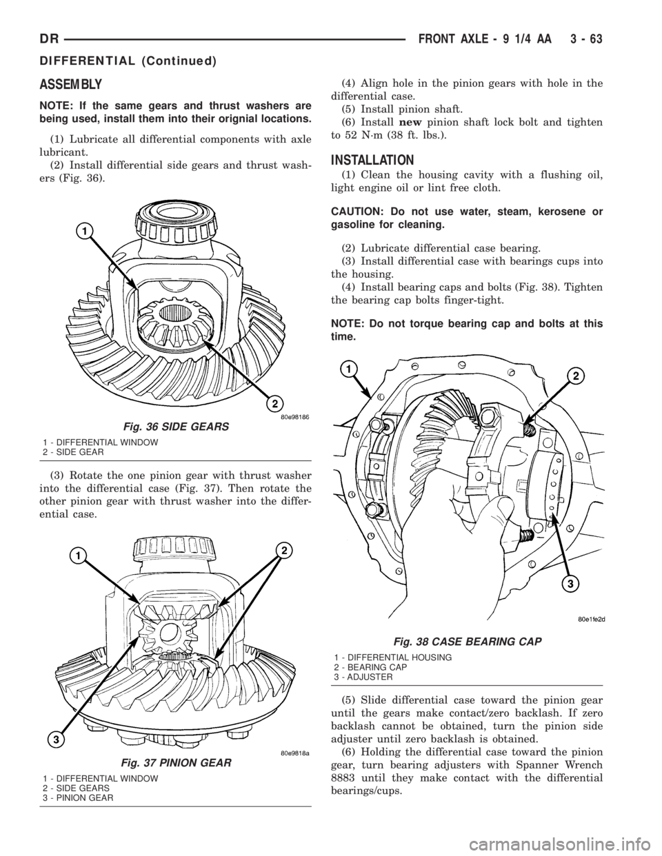
ers (Fig. 36).
(3) Rotate the one pinion gear with thrust washer
into the differential case (Fig. 37). Then rotate the
other pinion gear with thrust washer into the differ-
ential case.(4) Align hole in the pinion gears with hole in the
differential case.
(5) Install pinion shaft.
(6) Installnewpinion shaft lock bolt and tighten
to 52 N´m (38 ft. lbs.).
INSTALLATION
(1) Clean the housing cavity with a flushing oil,
light engine oil or lint free cloth.
CAUTION: Do not use water, steam, kerosene or
gasoline for cleaning.
(2) Lubricate differential case bearing.
(3) Install differential case with bearings cups into
the housing.
(4) Install bearing caps and bolts (Fig. 38). Tighten
the bearing cap bolts finger-tight.
NOTE: Do not torque bearing cap and bolts at this
time.
(5) Slide differential case toward the pinion gear
until the gears make contact/zero backlash. If zero
backlash cannot be obtained, turn the pinion side
adjuster until zero backlash is obtained.
(6) Holding the differential case toward the pinion
gear, turn bearing adjusters with Spanner Wrench
8883 until they make contact with the differential
bearings/cups.
Fig. 36 SIDE GEARS
1 - DIFFERENTIAL WINDOW
2 - SIDE GEAR
Fig. 37 PINION GEAR
1 - DIFFERENTIAL WINDOW
2 - SIDE GEARS
3 - PINION GEAR
Fig. 38 CASE BEARING CAP
1 - DIFFERENTIAL HOUSING
2 - BEARING CAP
3 - ADJUSTER
DRFRONT AXLE - 9 1/4 AA 3 - 63
DIFFERENTIAL (Continued)
Page 190 of 2895
(4) Install the other pinion gear and thrust
washer. Rotate the gears to align hole in the pinion
gears with hole in the differential case.
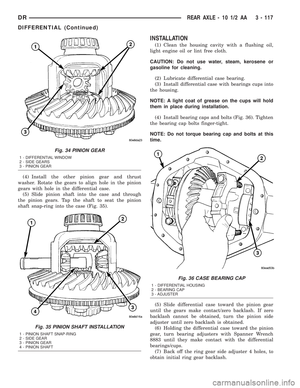
(5) Slide pinion shaft into the case and through
the pinion gears. Tap the shaft to seat the pinion
shaft snap-ring into the case (Fig. 35).
INSTALLATION
(1) Clean the housing cavity with a flushing oil,
light engine oil or lint free cloth.
CAUTION: Do not use water, steam, kerosene or
gasoline for cleaning.
(2) Lubricate differential case bearing.
(3) Install differential case with bearings cups into
the housing.
NOTE: A light coat of grease on the cups will hold
them in place during installation.
(4) Install bearing caps and bolts (Fig. 36). Tighten
the bearing cap bolts finger-tight.
NOTE: Do not torque bearing cap and bolts at this
time.
(5) Slide differential case toward the pinion gear
until the gears make contact/zero backlash. If zero
backlash cannot be obtained, turn the pinion side
adjuster until zero backlash is obtained.
(6) Holding the differential case toward the pinion
gear, turn bearing adjusters with Spanner Wrench
8883 until they make contact with the differential
bearings/cups.
(7) Back off the ring gear side adjuster 4 holes, to
obtain initial ring gear backlash.
Fig. 34 PINION GEAR
1 - DIFFERENTIAL WINDOW
2 - SIDE GEARS
3 - PINION GEAR
Fig. 35 PINION SHAFT INSTALLATION
1 - PINION SHAFT SNAP-RING
2 - SIDE GEAR
3 - PINION GEAR
4 - PINION SHAFT
Fig. 36 CASE BEARING CAP
1 - DIFFERENTIAL HOUSING
2 - BEARING CAP
3 - ADJUSTER
DRREAR AXLE - 10 1/2 AA 3 - 117
DIFFERENTIAL (Continued)
Page 217 of 2895
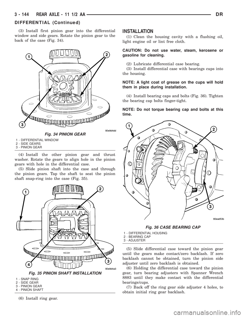
(3) Install first pinion gear into the differential
window and side gears. Rotate the pinion gear to the
back of the case (Fig. 34).
(4) Install the other pinion gear and thrust
washer. Rotate the gears to align hole in the pinion
gears with hole in the differential case.
(5) Slide pinion shaft into the case and through
the pinion gears. Tap the shaft to seat the pinion
shaft snap-ring into the case (Fig. 35).
(6) Install ring gear.INSTALLATION
(1) Clean the housing cavity with a flushing oil,
light engine oil or lint free cloth.
CAUTION: Do not use water, steam, kerosene or
gasoline for cleaning.
(2) Lubricate differential case bearing.
(3) Install differential case with bearings cups into
the housing.
NOTE: A light coat of grease on the cups will hold
them in place during installation.
(4) Install bearing caps and bolts (Fig. 36). Tighten
the bearing cap bolts finger-tight.
NOTE: Do not torque bearing cap and bolts at this
time.
(5) Slide differential case toward the pinion gear
until the gears make contact/zero backlash. If zero
backlash cannot be obtained, turn the pinion side
adjuster until zero backlash is obtained.
(6) Holding the differential case toward the pinion
gear, turn bearing adjusters with Spanner Wrench
8883 until they make contact with the differential
bearings/cups.
(7) Back off the ring gear side adjuster 4 holes, to
obtain initial ring gear backlash.
Fig. 34 PINION GEAR
1 - DIFFERENTIAL WINDOW
2 - SIDE GEARS
3 - PINION GEAR
Fig. 35 PINION SHAFT INSTALLATION
1 - SNAP RING
2 - SIDE GEAR
3 - PINION GEAR
4 - PINION SHAFT
Fig. 36 CASE BEARING CAP
1 - DIFFERENTIAL HOUSING
2 - BEARING CAP
3 - ADJUSTER
3 - 144 REAR AXLE - 11 1/2 AADR
DIFFERENTIAL (Continued)
Page 231 of 2895
and resulting fade can also be caused by riding the
brake pedal, making repeated high deceleration stops
in a short time span, or constant braking on steep
mountain roads. Refer to the Brake Drag information
in this section for causes.
BRAKE PULL
Front brake pull condition could result from:
²Contaminated lining in one caliper
²Seized caliper piston
²Binding caliper
²Loose caliper
²Rusty caliper slide surfaces
²Improper brake shoes
²Damaged rotor
A worn, damaged wheel bearing or suspension
component are further causes of pull. A damaged
front tire (bruised, ply separation) can also cause
pull.
A common and frequently misdiagnosed pull condi-
tion is where direction of pull changes after a few
stops. The cause is a combination of brake drag fol-
lowed by fade at one of the brake units.
As the dragging brake overheats, efficiency is so
reduced that fade occurs. Since the opposite brake
unit is still functioning normally, its braking effect is
magnified. This causes pull to switch direction in
favor of the normally functioning brake unit.
An additional point when diagnosing a change in
pull condition concerns brake cool down. Remember
that pull will return to the original direction, if the
dragging brake unit is allowed to cool down (and is
not seriously damaged).
REAR BRAKE GRAB OR PULL
Rear grab or pull is usually caused by improperly
adjusted or seized parking brake cables, contami-
nated lining, bent or binding shoes and support
plates, or improperly assembled components. This is
particularly true when only one rear wheel is
involved. However, when both rear wheels are
affected, the master cylinder or proportioning valve
could be at fault.
BRAKES DO NOT HOLD AFTER DRIVING THROUGH DEEP
WATER PUDDLES
This condition is generally caused by water soaked
lining. If the lining is only wet, it can be dried by
driving with the brakes very lightly applied for a
mile or two. However, if the lining is both soaked and
dirt contaminated, cleaning and/or replacement will
be necessary.
BRAKE LINING CONTAMINATION
Brake lining contamination is mostly a product of
leaking calipers or wheel cylinders, worn seals, driv-
ing through deep water puddles, or lining that hasbecome covered with grease and grit during repair.
Contaminated lining should be replaced to avoid fur-
ther brake problems.
WHEEL AND TIRE PROBLEMS
Some conditions attributed to brake components
may actually be caused by a wheel or tire problem.
A damaged wheel can cause shudder, vibration and
pull. A worn or damaged tire can also cause pull.
Severely worn tires with very little tread left can
produce a grab-like condition as the tire loses and
recovers traction. Flat-spotted tires can cause vibra-
tion and generate shudder during brake operation. A
tire with internal damage such as a severe bruise,
cut, or ply separation can cause pull and vibration.
BRAKE NOISES
Some brake noise is common with rear drum
brakes and on some disc brakes during the first few
stops after a vehicle has been parked overnight or
stored. This is primarily due to the formation of trace
corrosion (light rust) on metal surfaces. This light
corrosion is typically cleared from the metal surfaces
after a few brake applications causing the noise to
subside.
BRAKE SQUEAK/SQUEAL
Brake squeak or squeal may be due to linings that
are wet or contaminated with brake fluid, grease, or
oil. Glazed linings and rotors with hard spots can
also contribute to squeak. Dirt and foreign material
embedded in the brake lining will also cause squeak/
squeal.
A very loud squeak or squeal is frequently a sign of
severely worn brake lining. If the lining has worn
through to the brake shoes in spots, metal-to-metal
contact occurs. If the condition is allowed to continue,
rotors and drums can become so scored that replace-
ment is necessary.
BRAKE CHATTER
Brake chatter is usually caused by loose or worn
components, or glazed/burnt lining. Rotors with hard
spots can also contribute to chatter. Additional causes
of chatter are out-of-tolerance rotors, brake lining not
securely attached to the shoes, loose wheel bearings
and contaminated brake lining.
THUMP/CLUNK NOISE
Thumping or clunk noises during braking are fre-
quentlynotcaused by brake components. In many
cases, such noises are caused by loose or damaged
steering, suspension, or engine components. However,
calipers that bind on the slide surfaces can generate
a thump or clunk noise. In addition, worn out,
improperly adjusted, or improperly assembled rear
brake shoes can also produce a thump noise.
5 - 4 BRAKES - BASEDR
BRAKES - BASE (Continued)
Page 293 of 2895
lower inside sealing seat for nicks, cracks, paint, dirt
and solder residue. Inspect the radiator-to- reserve/
overflow tank hose for internal obstructions. Insert a
wire through the hose to be sure it is not obstructed.
Inspect the cams on the outside of the filler neck.
If the cams are damaged, seating of the pressure cap
valve and tester seal will be affected.
Attach pressure tester (7700 or an equivalent) to
radiator filler neck.
Operate the tester pump to apply 103.4 kPa (15
psi) pressure to the system. If the hoses enlarge
excessively or bulges while testing, replace as neces-
sary. Observe the gauge pointer and determine the
condition of the cooling system according to following
criteria:
Holds Steady:If the pointer remains steady for
two minutes, serious coolant leaks are not present in
system. However, there could be an internal leak
that does not appear with normal system test pres-
sure. If it is certain that coolant is being lost and
leaks cannot be detected, inspect for interior leakage
or perform Internal Leakage Test. Refer to INTER-
NAL LEAKAGE INSPECTION.
Drops Slowly:Indicates a small leak or seepage
is occurring. Examine all of the connections for seep-
age or slight leakage with a flashlight. Inspect the
radiator, hoses, gasket edges and heater. Seal the
small leak holes with a Sealer Lubricant (or equiva-
lent). Repair the leak holes and inspect the system
again with pressure applied.Drops Quickly:Indicates that serious leakage is
occurring. Examine the system for external leakage.
If leaks are not visible, inspect for internal leakage.
Large radiator leak holes should be repaired by a
reputable radiator repair shop.
INTERNAL LEAKAGE INSPECTION
Remove the engine oil pan drain plug and drain a
small amount of engine oil. If coolant is present in
the pan, it will drain first because it is heavier than
oil. An alternative method is to operate engine for a
short period to churn the oil. After this is done,
remove the engine dipstick and inspect for water
globules. Also inspect the transmission dipstick for
water globules and transmission fluid cooler for leak-
age.
WARNING: WITH RADIATOR PRESSURE TESTER
TOOL INSTALLED ON RADIATOR, DO NOT ALLOW
PRESSURE TO EXCEED 145 kPa (21 PSI). PRES-
SURE WILL BUILD UP QUICKLY IF A COMBUSTION
LEAK IS PRESENT. TO RELEASE PRESSURE,
ROCK TESTER FROM SIDE TO SIDE. WHEN
REMOVING TESTER, DO NOT TURN TESTER MORE
THAN 1/2 TURN IF SYSTEM IS UNDER PRESSURE.
Operate the engine without the pressure cap on
the radiator until the thermostat opens. Attach a
Pressure Tester to the filler neck. If pressure builds
up quickly it indicates a combustion leak exists. This
is usually the result of a cylinder head gasket leak or
crack in engine. Repair as necessary.
If there is not an immediate pressure increase,
pump the Pressure Tester. Do this until indicated
pressure is within system range of 110 kPa (16 psi).
Fluctuation of the gauge pointer indicates compres-
sion or combustion leakage into cooling system.
Because the vehicle is equipped with a catalytic
converter,do notshort out cylinders to isolate com-
pression leak.
If the needle on dial of the pressure tester does not
fluctuate, race engine a few times to check for an
abnormal amount of coolant or steam. This would be
emitting from exhaust pipe. Coolant or steam from
exhaust pipe may indicate a faulty cylinder head gas-
ket, cracked engine cylinder block or cylinder head.
A convenient check for exhaust gas leakage into
cooling system is provided by a commercially avail-
able Block Leak Check tool. Follow manufacturers
instructions when using this product.
COMBUSTION LEAKAGE TESTÐWITHOUT
PRESSURE TESTER
DO NOT WASTE reusable coolant. If the solution
is clean, drain the coolant into a clean container for
reuse.
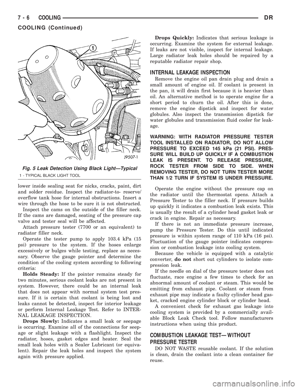
Fig. 5 Leak Detection Using Black LightÐTypical
1 - TYPICAL BLACK LIGHT TOOL
7 - 6 COOLINGDR
COOLING (Continued)
Page 307 of 2895
WARNING: DO NOT REMOVE OR LOOSEN THE
RADIATOR CAP WITH THE COOLING SYSTEM HOT
AND UNDER PRESSURE. SERIOUS BURNS FROM
THE COOLANT OR HIGH PRESSURE STEAM CAN
OCCUR.
For 3.7L / 4.7L/5.9L engines, remove the radiator
cap from the coolant degas bottle to add coolant.
SPECIFICATIONS
TORQUE
DESCRIPTION N´m Ft. In.
Lbs. Lbs.
Automatic Belt Tensioner to
BlockÐBolts 41 30 Ð
Automatic Belt Tensioner
PulleyÐBolt 61 45 Ð
Block HeaterÐBolt 2 Ð 17
Generator/Compressor
Mounting BracketÐBolts
# 1 and 2 54 40 Ð
# 3 40 30 Ð
Fan Shroud to Radiator
MountingÐBolts6Ð55
Radiator to Support - Bolts 8.5 Ð 75
Fan Blade to Viscous Fan
DriveÐBolts24 18 Ð
Idler PulleyÐBolt 54 40 Ð
Thermostat HousingÐBolts
- All Except 5.9L13 Ð 112
Thermostat HousingÐBolts
- 5.9L23 16 Ð
Power Steering Oil Cooler
Ð Bolts6Ð55
Transmission Auxiliary Oil
CoolerÐBolts 6 Ð 55
Transmission Oil Cooler
Tube Nuts31.5 24 Ð
Coolant Bottle Ð Bolts 8.5 Ð 75
Transmission Oil Cooler to
Transmission - 5.9L/46RE -
Tube Nuts 31.5 24 Ð
Transmission Oil Cooler to
Transmission - 3.7L/4.7L/
45RFE - Tube Nuts20 18 Ð
Water PumpÐBolts 24 18 Ð
Water Pump Ð Bolts - 4.7L 58 43 Ð
SPECIFICATIONS -
SPECIFICATIONS
DESCRIPTION SPECIFICATION
3.7/4.7L Engine 15.4L (16.2 qts.)- to the
middle of the cold fill
range
5.7L Engine 15.4L (16.2 qts.)- to the
middle of the cold fill
range
5.9L Engine 15.5L (16.3 qts.)- to the
MIN mark after 3 warm
up, cool down cycles
8.0L Engine 24L (25.3 qts.)
5.9L Diesel Engine 28L (29.5 qts.)
SPECIAL TOOLS
COOLING
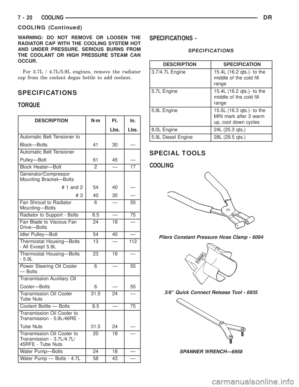
Pliers Constant Pressure Hose Clamp - 6094
3/8º Quick Connect Release Tool - 6935
SPANNER WRENCHÐ6958
7 - 20 COOLINGDR
COOLING (Continued)