2003 DODGE RAM engine oil pan
[x] Cancel search: engine oil panPage 325 of 2895
CAUTION: Do not use coolant additives that are
claimed to improve engine cooling.
OPERATION
Coolant flows through the engine block absorbing
the heat from the engine, then flows to the radiator
where the cooling fins in the radiator transfers the
heat from the coolant to the atmosphere. During cold
weather the ethylene-glycol or propylene-glycol cool-
ant prevents water present in the cooling system
from freezing within temperatures indicated by mix-
ture ratio of coolant to water.
COOLANT RECOVERY
CONTAINER-5.9L
DESCRIPTION
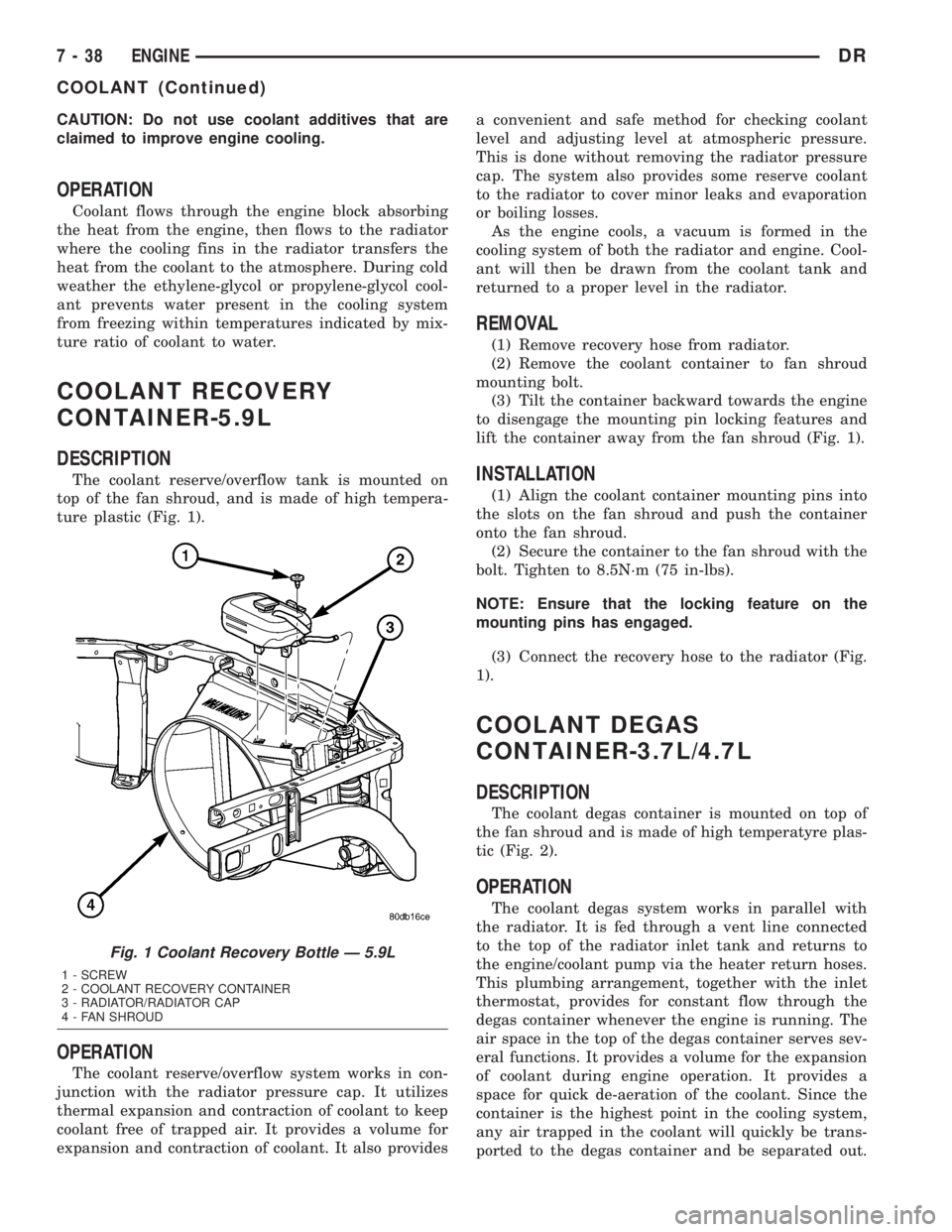
The coolant reserve/overflow tank is mounted on
top of the fan shroud, and is made of high tempera-
ture plastic (Fig. 1).
OPERATION
The coolant reserve/overflow system works in con-
junction with the radiator pressure cap. It utilizes
thermal expansion and contraction of coolant to keep
coolant free of trapped air. It provides a volume for
expansion and contraction of coolant. It also providesa convenient and safe method for checking coolant
level and adjusting level at atmospheric pressure.
This is done without removing the radiator pressure
cap. The system also provides some reserve coolant
to the radiator to cover minor leaks and evaporation
or boiling losses.
As the engine cools, a vacuum is formed in the
cooling system of both the radiator and engine. Cool-
ant will then be drawn from the coolant tank and
returned to a proper level in the radiator.
REMOVAL
(1) Remove recovery hose from radiator.
(2) Remove the coolant container to fan shroud
mounting bolt.
(3) Tilt the container backward towards the engine
to disengage the mounting pin locking features and
lift the container away from the fan shroud (Fig. 1).
INSTALLATION
(1) Align the coolant container mounting pins into
the slots on the fan shroud and push the container
onto the fan shroud.
(2) Secure the container to the fan shroud with the
bolt. Tighten to 8.5N´m (75 in-lbs).
NOTE: Ensure that the locking feature on the
mounting pins has engaged.
(3) Connect the recovery hose to the radiator (Fig.
1).
COOLANT DEGAS
CONTAINER-3.7L/4.7L
DESCRIPTION
The coolant degas container is mounted on top of
the fan shroud and is made of high temperatyre plas-
tic (Fig. 2).
OPERATION
The coolant degas system works in parallel with
the radiator. It is fed through a vent line connected
to the top of the radiator inlet tank and returns to
the engine/coolant pump via the heater return hoses.
This plumbing arrangement, together with the inlet
thermostat, provides for constant flow through the
degas container whenever the engine is running. The
air space in the top of the degas container serves sev-
eral functions. It provides a volume for the expansion
of coolant during engine operation. It provides a
space for quick de-aeration of the coolant. Since the
container is the highest point in the cooling system,
any air trapped in the coolant will quickly be trans-
ported to the degas container and be separated out.
Fig. 1 Coolant Recovery Bottle Ð 5.9L
1 - SCREW
2 - COOLANT RECOVERY CONTAINER
3 - RADIATOR/RADIATOR CAP
4 - FAN SHROUD
7 - 38 ENGINEDR
COOLANT (Continued)
Page 347 of 2895

(6) Remove the power steering cooler mounting
bolts and position the power steering cooler out of
the way.
(7) Disconnect the transmission cooler lines at the
transmission. The transmission cooler will remain on
the radiator and can be removed as an assembly.
(8) Remove the lower shroud assembly and the
electronic viscous fan wiring from the upper shroud
assembly.
(9) Remove the two radiator upper mounting bolts
(Fig. 36).
(10) Lift radiator straight up and out of engine
compartment. The bottom of the radiator is equipped
with two alignment dowels that fit into holes in the
lower radiator support panel. Rubber biscuits (insu-
lators) are installed to these dowels. Take care not to
damage cooling fins or tubes on the radiator and air
conditioning condenser when removing.
CLEANING
Clean radiator fins are necessary for good heat
transfer. The radiator and oil cooler fins should be
cleaned when an accumulation of debris has
occurred. With the engine cold, apply cold water and
compressed air to the back (engine side) of the radi-
ator to flush the radiator and/or oil coolers of debris.
INSPECTION
Inspect the radiator side tanks for cracks, broken
or missing fittings also inspect the joint where the
tanks seam up to the radiator core for signs of leak-
age and/or deteriorating seals.
Inspect radiator core for corroded, bent or missing
cooling fins. Inspect the core for bent or damaged
cooling tubes.
INSTALLATION
(1) Install rubber insulators to alignment dowels
at lower part of radiator.
(2) Lower the radiator into position while guiding
the two alignment dowels into lower radiator sup-
port. Different alignment holes are provided in the
lower radiator support for each engine application.
(3) Install two upper radiator mounting bolts.
Tighten bolts to 11 N´m (95 in. lbs.) torque.
(4) Connect both radiator hoses and install hose
clamps.
(5) Connect transmission cooler lines to radiator
tank. Inspect quick connect fittings for debris and
install until an audible ªclickº is heard. Pull apart to
verify connection.
(6) Position power steering cooler on the radiator
and tighten nuts to 8.5M´N (75 in. lbs.)
(7) Attach electronic viscous fan wiring to upper
shroud ands install lower shroud.
(8) Position coolant recover tank hose, washer bot-
tle hose and the positive battery cable into the clips
located on the top of the radiator.
(9) Install air box and turbocharger inlet hose.
Tighten clamps to 4 N´M (35 in. lbs.).
(10) Position heater controls tofull heatposition.
(11) Fill cooling system with coolant (Refer to 7 -
COOLING - STANDARD PROCEDURE).
(12) Operate engine until it reaches normal tem-
perature. Check cooling system and automatic trans-
mission (if equipped) fluid levels.
RADIATOR PRESSURE CAP
DESCRIPTION
All cooling systems are equipped with a pressure
cap (Fig. 37). For 5.9L engines, the pressure cap is
located on top of the radiator outlet tank. For the
3.7L/4.7L engines, the pressure cap is located on top
of the coolant degas container. The cap releases pres-
sure at some point within a range of 97-to-124 kPa
(14-to-18 psi). The pressure relief point (in pounds) is
engraved on top of the cap
The cooling system will operate at pressures
slightly above atmospheric pressure. This results in a
higher coolant boiling point allowing increased radi-
ator cooling capacity. The cap contains a spring-
Fig. 36 Fan Shroud MountingÐ5.9L Diesel Engine
1 - RADIATOR SUPPORT
2 - UPPER FAN SHROUD
3 - BOLTS (2)
4 - LOWER FAN SHROUD
5 - RADIATOR
7 - 60 ENGINEDR
RADIATOR - 5.9L DIESEL (Continued)
Page 359 of 2895
TRANSMISSION
TABLE OF CONTENTS
page page
TRANS COOLER
DESCRIPTION
DESCRIPTION........................72
DESCRIPTION........................72
OPERATION...........................72
REMOVAL.............................72
DISASSEMBLY - 5.9L ONLY...............73
ASSEMBLY - 5.9L ONLY..................73
INSTALLATION.........................73TRANS COOLER - 5.9L DIESEL
DESCRIPTION.........................73
OPERATION...........................74
REMOVAL
REMOVALÐAIR TO OIL COOLER.........74
REMOVALÐWATER TO OIL COOLER......74
INSTALLATION
INSTALLATIONÐAIR TO OIL COOLER.....75
INSTALLATION.......................75
TRANS COOLER
DESCRIPTION
DESCRIPTION
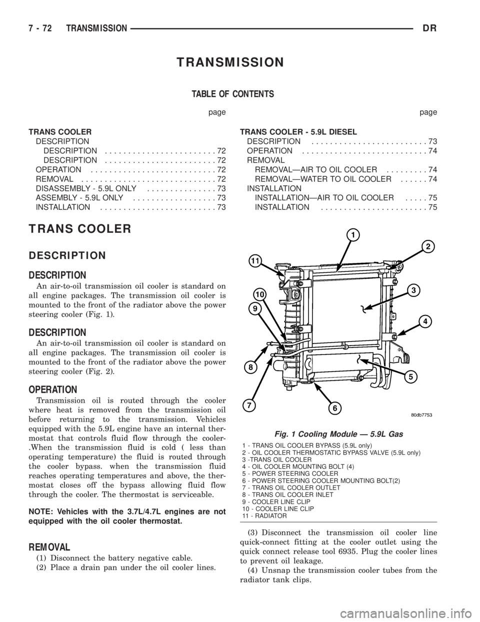
An air-to-oil transmission oil cooler is standard on
all engine packages. The transmission oil cooler is
mounted to the front of the radiator above the power
steering cooler (Fig. 1).
DESCRIPTION
An air-to-oil transmission oil cooler is standard on
all engine packages. The transmission oil cooler is
mounted to the front of the radiator above the power
steering cooler (Fig. 2).
OPERATION
Transmission oil is routed through the cooler
where heat is removed from the transmission oil
before returning to the transmission. Vehicles
equipped with the 5.9L engine have an internal ther-
mostat that controls fluid flow through the cooler-
.When the transmission fluid is cold ( less than
operating temperature) the fluid is routed through
the cooler bypass. when the transmission fluid
reaches operating temperatures and above, the ther-
mostat closes off the bypass allowing fluid flow
through the cooler. The thermostat is serviceable.
NOTE: Vehicles with the 3.7L/4.7L engines are not
equipped with the oil cooler thermostat.
REMOVAL
(1) Disconnect the battery negative cable.
(2) Place a drain pan under the oil cooler lines.(3) Disconnect the transmission oil cooler line
quick-connect fitting at the cooler outlet using the
quick connect release tool 6935. Plug the cooler lines
to prevent oil leakage.
(4) Unsnap the transmission cooler tubes from the
radiator tank clips.
Fig. 1 Cooling Module Ð 5.9L Gas
1 - TRANS OIL COOLER BYPASS (5.9L only)
2 - OIL COOLER THERMOSTATIC BYPASS VALVE (5.9L only)
3 -TRANS OIL COOLER
4 - OIL COOLER MOUNTING BOLT (4)
5 - POWER STEERING COOLER
6 - POWER STEERING COOLER MOUNTING BOLT(2)
7 - TRANS OIL COOLER OUTLET
8 - TRANS OIL COOLER INLET
9 - COOLER LINE CLIP
10 - COOLER LINE CLIP
11 - RADIATOR
7 - 72 TRANSMISSIONDR
Page 361 of 2895
ers are supplied as standard equipment on diesel
engine powered models when equipped with an auto-
matic transmission.
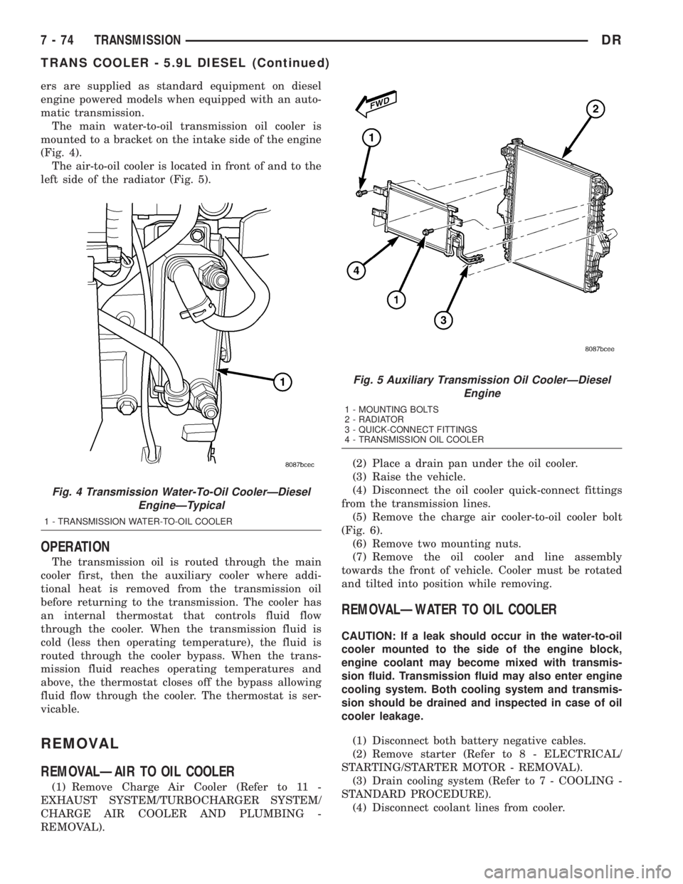
The main water-to-oil transmission oil cooler is
mounted to a bracket on the intake side of the engine
(Fig. 4).
The air-to-oil cooler is located in front of and to the
left side of the radiator (Fig. 5).
OPERATION
The transmission oil is routed through the main
cooler first, then the auxiliary cooler where addi-
tional heat is removed from the transmission oil
before returning to the transmission. The cooler has
an internal thermostat that controls fluid flow
through the cooler. When the transmission fluid is
cold (less then operating temperature), the fluid is
routed through the cooler bypass. When the trans-
mission fluid reaches operating temperatures and
above, the thermostat closes off the bypass allowing
fluid flow through the cooler. The thermostat is ser-
vicable.
REMOVAL
REMOVALÐAIR TO OIL COOLER
(1) Remove Charge Air Cooler (Refer to 11 -
EXHAUST SYSTEM/TURBOCHARGER SYSTEM/
CHARGE AIR COOLER AND PLUMBING -
REMOVAL).(2) Place a drain pan under the oil cooler.
(3) Raise the vehicle.
(4) Disconnect the oil cooler quick-connect fittings
from the transmission lines.
(5) Remove the charge air cooler-to-oil cooler bolt
(Fig. 6).
(6) Remove two mounting nuts.
(7) Remove the oil cooler and line assembly
towards the front of vehicle. Cooler must be rotated
and tilted into position while removing.
REMOVALÐWATER TO OIL COOLER
CAUTION: If a leak should occur in the water-to-oil
cooler mounted to the side of the engine block,
engine coolant may become mixed with transmis-
sion fluid. Transmission fluid may also enter engine
cooling system. Both cooling system and transmis-
sion should be drained and inspected in case of oil
cooler leakage.
(1) Disconnect both battery negative cables.
(2) Remove starter (Refer to 8 - ELECTRICAL/
STARTING/STARTER MOTOR - REMOVAL).
(3) Drain cooling system (Refer to 7 - COOLING -
STANDARD PROCEDURE).
(4) Disconnect coolant lines from cooler.
Fig. 4 Transmission Water-To-Oil CoolerÐDiesel
EngineÐTypical
1 - TRANSMISSION WATER-TO-OIL COOLER
Fig. 5 Auxiliary Transmission Oil CoolerÐDiesel
Engine
1 - MOUNTING BOLTS
2 - RADIATOR
3 - QUICK-CONNECT FITTINGS
4 - TRANSMISSION OIL COOLER
7 - 74 TRANSMISSIONDR
TRANS COOLER - 5.9L DIESEL (Continued)
Page 393 of 2895

²supplies a reference voltage for the Throttle
Position Sensor (TPS) sensor.
Secondary 5±volt supply:
²supplies the required 5 volt power source to the
oil pressure sensor.
²supplies the required 5 volt power source for the
Vehicle Speed Sensor (VSS) (if equipped).
²supplies the 5 volt power source to the transmis-
sion pressure sensor (certain automatic transmis-
sions).
OPERATION - IGNITION CIRCUIT SENSE
The ignition circuit sense input tells the PCM the
ignition switch has energized the ignition circuit.
Battery voltage is also supplied to the PCM
through the ignition switch when the ignition is in
the RUN or START position. This is referred to as
the9ignition sense9circuit and is used to9wake up9
the PCM. Voltage on the ignition input can be as low
as 6 volts and the PCM will still function. Voltage is
supplied to this circuit to power the PCM's 8-volt reg-
ulator and to allow the PCM to perform fuel, ignition
and emissions control functions.
REMOVAL
USE THE DRB SCAN TOOL TO REPROGRAM
THE NEW POWERTRAIN CONTROL MODULE
(PCM) WITH THE VEHICLES ORIGINAL IDEN-
TIFICATION NUMBER (VIN) AND THE VEHI-
CLES ORIGINAL MILEAGE. IF THIS STEP IS
NOT DONE, A DIAGNOSTIC TROUBLE CODE
(DTC) MAY BE SET.
The PCM is located in the engine compartment
attached to the dash panel (Fig. 6).
To avoid possible voltage spike damage to the
PCM, ignition key must be off, and negative battery
cable must be disconnected before unplugging PCM
connectors.
(1) Disconnect negative battery cable at battery.
(2) Remove cover over electrical connectors. Cover
snaps onto PCM.
(3) Carefully unplug the three 32±way connectors
(four 38±way connectors if equipped with NGC) from
PCM (Fig. 7).
(4) Remove three PCM mounting bolts (Fig. 7) and
remove PCM from vehicle.
INSTALLATION
USE THE DRB SCAN TOOL TO REPROGRAM
THE NEW POWERTRAIN CONTROL MODULE
(PCM) WITH THE VEHICLES ORIGINAL IDEN-
TIFICATION NUMBER (VIN) AND THE VEHI-
CLES ORIGINAL MILEAGE. IF THIS STEP IS
NOT DONE, A DIAGNOSTIC TROUBLE CODE
(DTC) MAY BE SET.
(1) Install PCM and 3 mounting bolts to vehicle.
Fig. 6 PCM LOCATION
1 - COWL GRILL
2 - PCM
3 - COWL (RIGHT-REAR)
Fig. 7 PCM REMOVAL / INSTALLATION
1 - THREE 32-WAY CONNECTORS WITH JTEC (FOUR 38-WAY
CONNECTORS WITH NGC)
2 - PCM MOUNTING BRACKET
3 - PCM
4 - PCM MOUNTING SCREWS (3)
8E - 12 ELECTRONIC CONTROL MODULESDR
POWERTRAIN CONTROL MODULE (Continued)
Page 424 of 2895

CHARGING
TABLE OF CONTENTS
page page
CHARGING
DESCRIPTION.........................19
OPERATION...........................19
DIAGNOSIS AND TESTING - CHARGING
SYSTEM............................19
SPECIFICATIONS
GENERATOR RATINGS.................20
SPECIFICATIONS - TORQUE - GENERATOR
/ CHARGING SYSTEM..................20
BATTERY TEMPERATURE SENSOR
DESCRIPTION.........................21OPERATION...........................21
REMOVAL.............................21
INSTALLATION.........................21
GENERATOR
DESCRIPTION.........................22
OPERATION...........................22
REMOVAL.............................22
INSTALLATION.........................25
VOLTAGE REGULATOR
DESCRIPTION.........................27
OPERATION...........................27
CHARGING
DESCRIPTION
The charging system consists of:
²Generator
²Electronic Voltage Regulator (EVR) circuitry
within the Powertrain Control Module (PCM). Elec-
tronic Control Module (ECM) for diesel engines.
²Ignition switch
²Battery (refer to 8, Battery for information)
²Battery temperature sensor
²Check Gauges Lamp (if equipped)
²Voltmeter (refer to 8, Instrument Panel and
Gauges for information)
²Wiring harness and connections (refer to 8, Wir-
ing Diagrams for information)
OPERATION
The charging system is turned on and off with the
ignition switch. The system is on when the engine is
running and the ASD relay is energized. When the
ASD relay is on, voltage is supplied to the ASD relay
sense circuit at the PCM (ECM Diesel). This voltage
is connected through the PCM (ECM Diesel) and sup-
plied to one of the generator field terminals (Gen.
Source +) at the back of the generator.
The amount of direct current produced by the gen-
erator is controlled by the EVR (field control) cir-
cuitry contained within the PCM (ECM Diesel). This
circuitry is connected in series with the second rotor
field terminal and ground.
A battery temperature sensor, located in the bat-
tery tray housing, is used to sense battery tempera-
ture. This temperature data, along with data from
monitored line voltage, is used by the PCM (ECM
Diesel) to vary the battery charging rate. This isdone by cycling the ground path to control the
strength of the rotor magnetic field. The PCM then
compensates and regulates generator current output
accordingly.
All vehicles are equipped with On-Board Diagnos-
tics (OBD). All OBD-sensed systems, including EVR
(field control) circuitry, are monitored by the PCM
(ECM Diesel). Each monitored circuit is assigned a
Diagnostic Trouble Code (DTC). The PCM will store a
DTC in electronic memory for certain failures it
detects.
The Check Gauges Lamp (if equipped) monitors:
charging system voltage,engine coolant tempera-
ture and engine oil pressure. If an extreme condition
is indicated, the lamp will be illuminated. This is
done as reminder to check the three gauges. The sig-
nal to activate the lamp is sent via the CCD bus cir-
cuits. The lamp is located on the instrument panel.
Refer to 8, Instrument Panel and Gauges for addi-
tional information.
DIAGNOSIS AND TESTING - CHARGING
SYSTEM
The following procedures may be used to diagnose
the charging system if:
²the check gauges lamp (if equipped) is illumi-
nated with the engine running
²the voltmeter (if equipped) does not register
properly
²an undercharged or overcharged battery condi-
tion occurs.
Remember that an undercharged battery is often
caused by:
²accessories being left on with the engine not
running
DRCHARGING 8F - 19
Page 498 of 2895

the vehicle speed remains greater than about twenty-
four kilometers-per-hour (fifteen miles-per-hour).
²Vacuum Fluorescent Display Synchroniza-
tion- The EMIC transmits electronic panel lamp
dimming level messages which allows all other elec-
tronic modules on the PCI data bus with Vacuum
Fluorescent Display (VFD) units to coordinate their
illumination intensity with that of the EMIC VFD
units.
²Vehicle Theft Security System- The EMIC
monitors inputs from the door cylinder lock switch-
(es), the door ajar switches, the ignition switch, and
the Remote Keyless Entry (RKE) receiver module,
then provides electronic horn and lighting request
messages to the Front Control Module (FCM) located
on the Integrated Power Module (IPM) for the appro-
priate VTSS alarm output features.
²Wiper/Washer System Control- The EMIC
provides electronic wiper and/or washer request mes-
sages to the Front Control Module (FCM) located on
the Integrated Power Module (IPM) for the appropri-
ate wiper and washer system features. (Refer to 8 -
ELECTRICAL/WIPERS/WASHERS - DESCRIP-
TION).
The EMIC houses six analog gauges and has pro-
visions for up to twenty-three indicators (Fig. 3) or
(Fig. 4). The EMIC includes the following analog
gauges:
²Coolant Temperature Gauge
²Fuel Gauge
²Oil Pressure Gauge
²Speedometer
²Tachometer
²Voltage Gauge
Some of the EMIC indicators are automatically
configured when the EMIC is connected to the vehi-
cle electrical system for compatibility with certain
optional equipment or equipment required for regula-
tory purposes in certain markets. While each EMIC
may have provisions for indicators to support every
available option, the configurable indicators will not
be functional in a vehicle that does not have the
equipment that an indicator supports. The EMIC
includes provisions for the following indicators (Fig.
3) or (Fig. 4):
²Airbag Indicator (with Airbag System only)
²Antilock Brake System (ABS) Indicator
(with ABS or Rear Wheel Anti-Lock [RWAL]
brakes only)
²Brake Indicator
²Cargo Lamp Indicator
²Check Gauges Indicator
²Cruise Indicator (with Speed Control only)
²Door Ajar Indicator
²Electronic Throttle Control (ETC) Indicator
(with 5.7L Gasoline Engine only)²Gear Selector Indicator (with Automatic
Transmission only)
²High Beam Indicator
²Lamp Out Indicator
²Low Fuel Indicator
²Malfunction Indicator Lamp (MIL)
²Overdrive-Off Indicator (with Automatic
Transmission only)
²Seatbelt Indicator
²Security Indicator (with Sentry Key Immo-
bilizer & Vehicle Theft Security Systems only)
²Service Four-Wheel Drive Indicator (with
Four-Wheel Drive only)
²Transmission Overtemp Indicator (with
Automatic Transmission only)
²Turn Signal (Right and Left) Indicators
²Upshift Indicator (with Manual Transmis-
sion only)
²Washer Fluid Indicator
²Wait-To-Start Indicator (with Diesel Engine
only)
²Water-In-Fuel Indicator (with Diesel Engine
only)
Each indicator in the EMIC, except those located
within one of the VFD units, is illuminated by a ded-
icated LED that is soldered onto the EMIC electronic
circuit board. The LED units are not available for
service replacement and, if damaged or faulty, the
entire EMIC must be replaced. Cluster illumination
is accomplished by dimmable incandescent back
lighting, which illuminates the gauges for visibility
when the exterior lighting is turned on. Each of the
incandescent bulbs is secured by an integral bulb
holder to the electronic circuit board from the back of
the cluster housing.
Hard wired circuitry connects the EMIC to the
electrical system of the vehicle. These hard wired cir-
cuits are integral to several wire harnesses, which
are routed throughout the vehicle and retained by
many different methods. These circuits may be con-
nected to each other, to the vehicle electrical system
and to the EMIC through the use of a combination of
soldered splices, splice block connectors, and many
different types of wire harness terminal connectors
and insulators. Refer to the appropriate wiring infor-
mation. The wiring information includes wiring dia-
grams, proper wire and connector repair procedures,
further details on wire harness routing and reten-
tion, as well as pin-out and location views for the
various wire harness connectors, splices and grounds.
The EMIC modules for this model are serviced only
as complete units. The EMIC module cannot be
adjusted or repaired. If a gauge, an LED indicator, a
VFD unit, the electronic circuit board, the circuit
board hardware, the cluster overlay, or the EMIC
housing are damaged or faulty, the entire EMIC mod-
DRINSTRUMENT CLUSTER 8J - 5
INSTRUMENT CLUSTER (Continued)
Page 499 of 2895

ule must be replaced. The cluster lens, hood and
mask unit and the individual incandescent lamp
bulbs with holders are available for individual ser-
vice replacement.
OPERATION
The ElectroMechanical Instrument Cluster (EMIC)
in this model also includes the hardware and soft-
ware necessary to serve as the electronic body control
module and is sometimes referred to as the Cab
Compartment Node or CCN. The following informa-
tion deals primarily with the instrument cluster
functions of this unit. Additional details of the elec-
tronic body control functions of this unit may be
found within the service information for the system
or component that the EMIC controls. For example:
Additional details of the audible warning functions of
the EMIC are found within the Chime/Buzzer service
information.The EMIC is designed to allow the vehicle operator
to monitor the conditions of many of the vehicle com-
ponents and operating systems. The gauges and indi-
cators in the EMIC provide valuable information
about the various standard and optional powertrains,
fuel and emissions systems, cooling systems, lighting
systems, safety systems and many other convenience
items. The EMIC is installed in the instrument panel
so that all of these monitors can be easily viewed by
the vehicle operator when driving, while still allow-
ing relative ease of access for service. The micropro-
cessor-based EMIC hardware and software uses
various inputs to control the gauges and indicators
visible on the face of the cluster. Some of these
inputs are hard wired, but most are in the form of
electronic messages that are transmitted by other
electronic modules over the Programmable Communi-
cations Interface (PCI) data bus network. (Refer to 8
- ELECTRICAL/ELECTRONIC CONTROL MOD-
ULES/COMMUNICATION - OPERATION).
Fig. 3 Gauges & Indicators - Gasoline Engine
1 - MALFUNCTION INDICATOR LAMP 13 - ELECTRONIC THROTTLE CONTROL (ETC) INDICATOR
2 - VOLTAGE GAUGE 14 - ENGINE TEMPERATURE GAUGE
3 - LEFT TURN INDICATOR 15 - SECURITY INDICATOR
4 - TACHOMETER 16 - GEAR SELECTOR INDICATOR DISPLAY (INCLUDES
CRUISE & UPSHIFT INDICATORS)
5 - AIRBAG INDICATOR 17 - CHECK GAUGES INDICATOR
6 - HIGH BEAM INDICATOR 18 - BRAKE INDICATOR
7 - SEATBELT INDICATOR 19 - ABS INDICATOR
8 - SPEEDOMETER 20 - ODOMETER/TRIP ODOMETER DISPLAY (INCLUDES
ENGINE HOURS, WASHER FLUID, LAMP OUTAGE,
OVERDRIVE-OFF & SERVICE 4x4 INDICATORS)
9 - RIGHT TURN INDICATOR 21 - ODOMETER/TRIP ODOMETER SWITCH BUTTON
10 - OIL PRESSURE GAUGE 22 - FUEL GAUGE
11 - CARGO LAMP INDICATOR 23 - LOW FUEL INDICATOR
12 - DOOR AJAR INDICATOR 24 - TRANSMISSION OVERTEMP INDICATOR
8J - 6 INSTRUMENT CLUSTERDR
INSTRUMENT CLUSTER (Continued)