2003 DODGE RAM bolt pattern
[x] Cancel search: bolt patternPage 94 of 2895
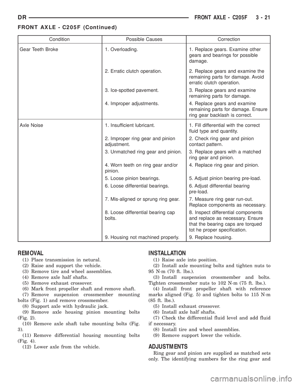
Condition Possible Causes Correction
Gear Teeth Broke 1. Overloading. 1. Replace gears. Examine other
gears and bearings for possible
damage.
2. Erratic clutch operation. 2. Replace gears and examine the
remaining parts for damage. Avoid
erratic clutch operation.
3. Ice-spotted pavement. 3. Replace gears and examine
remaining parts for damage.
4. Improper adjustments. 4. Replace gears and examine
remaining parts for damage. Ensure
ring gear backlash is correct.
Axle Noise 1. Insufficient lubricant. 1. Fill differential with the correct
fluid type and quantity.
2. Improper ring gear and pinion
adjustment.2. Check ring gear and pinion
contact pattern.
3. Unmatched ring gear and pinion. 3. Replace gears with a matched
ring gear and pinion.
4. Worn teeth on ring gear and/or
pinion.4. Replace ring gear and pinion.
5. Loose pinion bearings. 5. Adjust pinion bearing pre-load.
6. Loose differential bearings. 6. Adjust differential bearing
pre-load.
7. Mis-aligned or sprung ring gear. 7. Measure ring gear run-out.
Replace components as necessary.
8. Loose differential bearing cap
bolts.8. Inspect differential components
and replace as necessary. Ensure
that the bearing caps are torqued
tot he proper specification.
9. Housing not machined properly. 9. Replace housing.
REMOVAL
(1) Place transmission in netural.
(2) Raise and support the vehicle.
(3) Remove tire and wheel assemblies.
(4) Remove axle half shafts.
(5) Remove exhaust crossover.
(6) Mark front propeller shaft and remove shaft.
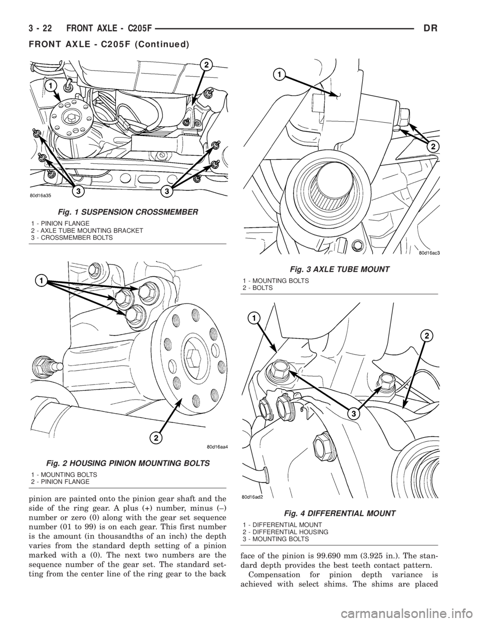
(7) Remove suspension crossmember mounting
bolts (Fig. 1) and remove crossmember.
(8) Support axle with hydraulic jack.
(9) Remove axle housing pinion mounting bolts
(Fig. 2).
(10) Remove axle shaft tube mounting bolts (Fig.
3).
(11) Remove differential housing mounting bolts
(Fig. 4).
(12) Lower axle from the vehicle.
INSTALLATION
(1) Raise axle into position.
(2) Install axle mounting bolts and tighten nuts to
95 N´m (70 ft. lbs.).
(3) Install suspension crossmember and bolts.
Tighten crossmember nuts to 102 N´m (75 ft. lbs.).
(4) Install front propeller shaft with reference
marks aligned (Fig. 5) and tighten bolts to 115 N´m
(85 ft. lbs.).
(5) Install exhaust crossover.
(6) Install axle half shafts.
(7) Check the differential fluid level and add fluid
if necessary.
(8) Install tire and wheel assemblies.
(9) Remove support lower the vehicle.
ADJUSTMENTS
Ring gear and pinion are supplied as matched sets
only. The identifying numbers for the ring gear and
DRFRONT AXLE - C205F 3 - 21
FRONT AXLE - C205F (Continued)
Page 95 of 2895
pinion are painted onto the pinion gear shaft and the
side of the ring gear. A plus (+) number, minus (±)
number or zero (0) along with the gear set sequence
number (01 to 99) is on each gear. This first number
is the amount (in thousandths of an inch) the depth
varies from the standard depth setting of a pinion
marked with a (0). The next two numbers are the
sequence number of the gear set. The standard set-
ting from the center line of the ring gear to the backface of the pinion is 99.690 mm (3.925 in.). The stan-
dard depth provides the best teeth contact pattern.
Compensation for pinion depth variance is
achieved with select shims. The shims are placed
Fig. 1 SUSPENSION CROSSMEMBER
1 - PINION FLANGE
2 - AXLE TUBE MOUNTING BRACKET
3 - CROSSMEMBER BOLTS
Fig. 2 HOUSING PINION MOUNTING BOLTS
1 - MOUNTING BOLTS
2 - PINION FLANGE
Fig. 3 AXLE TUBE MOUNT
1 - MOUNTING BOLTS
2 - BOLTS
Fig. 4 DIFFERENTIAL MOUNT
1 - DIFFERENTIAL MOUNT
2 - DIFFERENTIAL HOUSING
3 - MOUNTING BOLTS
3 - 22 FRONT AXLE - C205FDR
FRONT AXLE - C205F (Continued)
Page 98 of 2895
(9) Remove the pinion depth gauge components
from the housing
DIFFERENTIAL BEARING PRELOAD AND GEAR
BACKLASH
Differential side bearing preload and gear backlash
is achieved by selective shims inserted between the
bearing cup and the housing. The proper shim thick-
ness can be determined using slip-fit Dummy Bear-
ings 8398 in place of the differential side bearings
and a Dial Indicator C-3339. Before proceeding with
the differential bearing preload and gear backlash
measurements, measure the pinion gear depth and
prepare the pinion for installation. Establishing
proper pinion gear depth is essential to establishing
gear backlash and tooth contact patterns. After the
overall shim thickness to take up differential side
play is measured, the pinion is installed, and the
gear backlash shim thickness is measured. The over-
all shim thickness is the total of the dial indicator
reading, starting point shim thicknesses, and the
preload specification added together. The gear back-
lash measurement determines the thickness of the
shim used on the ring gear side of the differential
case. Subtract the gear backlash shim thickness from
the total overall shim thickness and select that
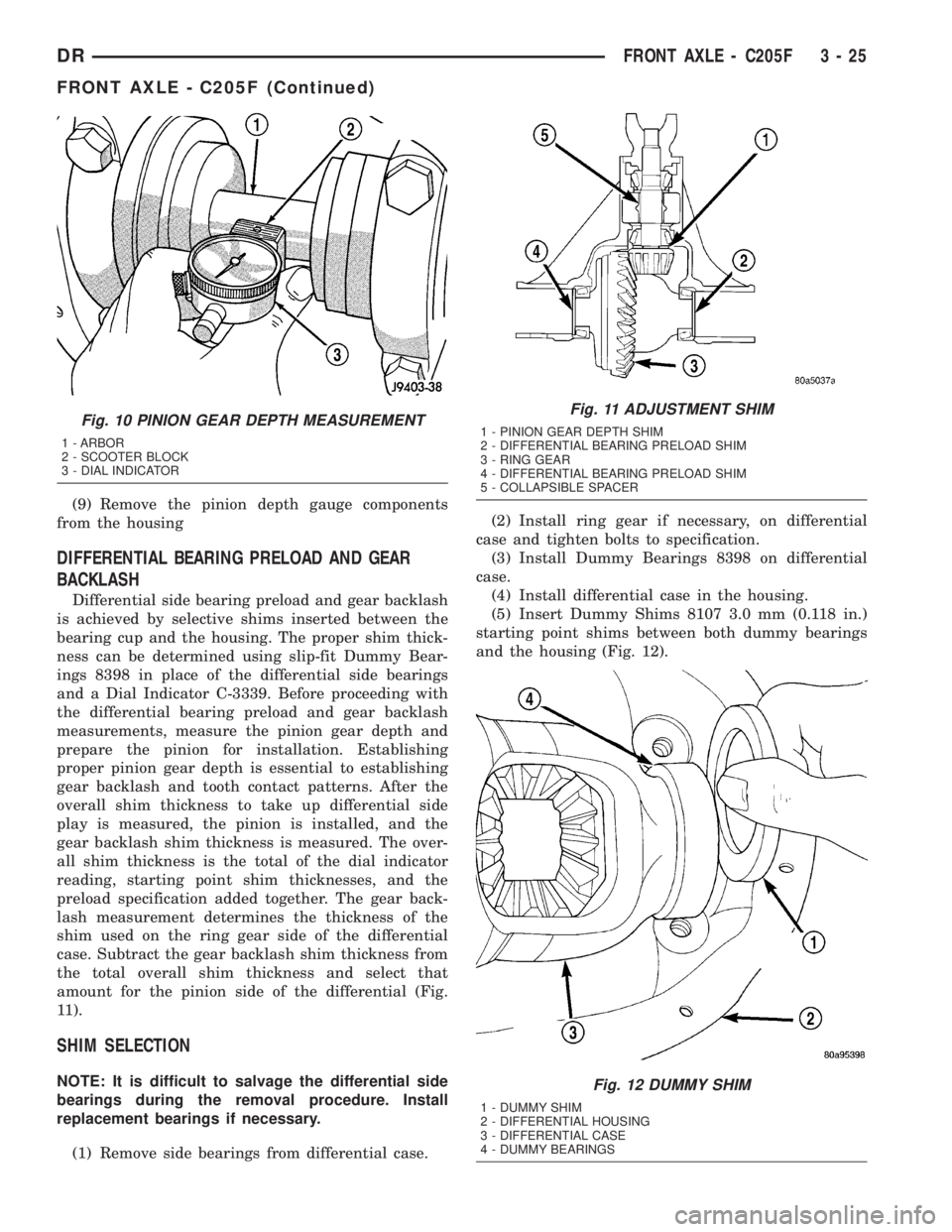
amount for the pinion side of the differential (Fig.
11).
SHIM SELECTION
NOTE: It is difficult to salvage the differential side
bearings during the removal procedure. Install
replacement bearings if necessary.
(1) Remove side bearings from differential case.(2) Install ring gear if necessary, on differential
case and tighten bolts to specification.
(3) Install Dummy Bearings 8398 on differential
case.
(4) Install differential case in the housing.
(5) Insert Dummy Shims 8107 3.0 mm (0.118 in.)
starting point shims between both dummy bearings
and the housing (Fig. 12).
Fig. 10 PINION GEAR DEPTH MEASUREMENT
1 - ARBOR
2 - SCOOTER BLOCK
3 - DIAL INDICATOR
Fig. 11 ADJUSTMENT SHIM
1 - PINION GEAR DEPTH SHIM
2 - DIFFERENTIAL BEARING PRELOAD SHIM
3 - RING GEAR
4 - DIFFERENTIAL BEARING PRELOAD SHIM
5 - COLLAPSIBLE SPACER
Fig. 12 DUMMY SHIM
1 - DUMMY SHIM
2 - DIFFERENTIAL HOUSING
3 - DIFFERENTIAL CASE
4 - DUMMY BEARINGS
DRFRONT AXLE - C205F 3 - 25
FRONT AXLE - C205F (Continued)
Page 101 of 2895
(34) Zero dial indicator face to pointer.
(35) Push and hold ring gear downward while not
allowing the pinion gear to rotate. Dial indicator
reading should be between 0.12 mm (0.005 in.) and
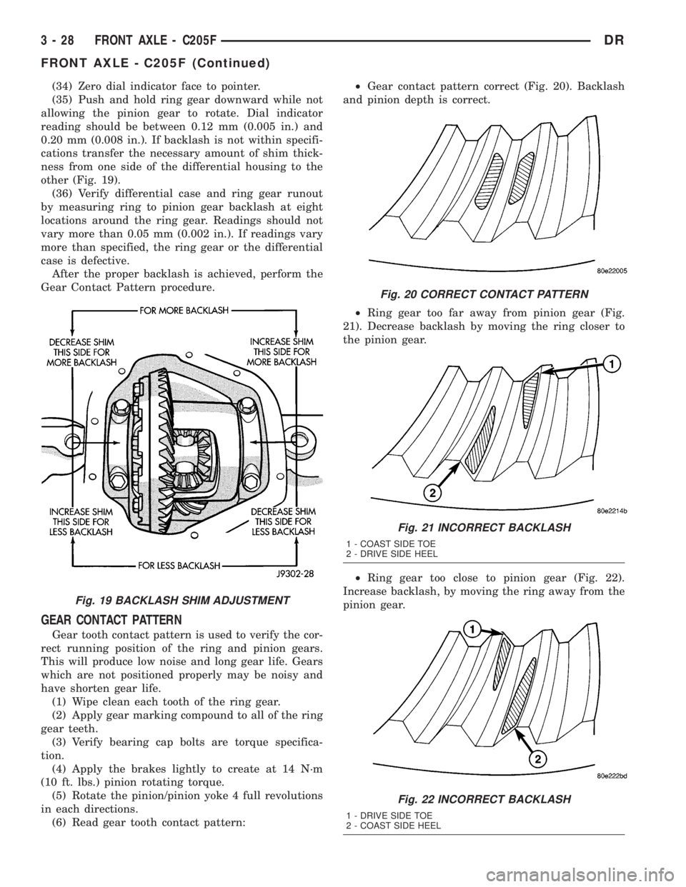
0.20 mm (0.008 in.). If backlash is not within specifi-
cations transfer the necessary amount of shim thick-
ness from one side of the differential housing to the
other (Fig. 19).
(36) Verify differential case and ring gear runout
by measuring ring to pinion gear backlash at eight
locations around the ring gear. Readings should not
vary more than 0.05 mm (0.002 in.). If readings vary
more than specified, the ring gear or the differential
case is defective.
After the proper backlash is achieved, perform the
Gear Contact Pattern procedure.
GEAR CONTACT PATTERN
Gear tooth contact pattern is used to verify the cor-
rect running position of the ring and pinion gears.
This will produce low noise and long gear life. Gears
which are not positioned properly may be noisy and
have shorten gear life.
(1) Wipe clean each tooth of the ring gear.
(2) Apply gear marking compound to all of the ring
gear teeth.
(3) Verify bearing cap bolts are torque specifica-
tion.
(4) Apply the brakes lightly to create at 14 N´m
(10 ft. lbs.) pinion rotating torque.
(5) Rotate the pinion/pinion yoke 4 full revolutions
in each directions.
(6) Read gear tooth contact pattern:²Gear contact pattern correct (Fig. 20). Backlash
and pinion depth is correct.
²Ring gear too far away from pinion gear (Fig.
21). Decrease backlash by moving the ring closer to
the pinion gear.
²Ring gear too close to pinion gear (Fig. 22).
Increase backlash, by moving the ring away from the
pinion gear.
Fig. 19 BACKLASH SHIM ADJUSTMENT
Fig. 20 CORRECT CONTACT PATTERN
Fig. 21 INCORRECT BACKLASH
1 - COAST SIDE TOE
2 - DRIVE SIDE HEEL
Fig. 22 INCORRECT BACKLASH
1 - DRIVE SIDE TOE
2 - COAST SIDE HEEL
3 - 28 FRONT AXLE - C205FDR
FRONT AXLE - C205F (Continued)
Page 112 of 2895

(3) Spread housing and measure the distance with
the dial indicator.
CAUTION: Never spread over 0.50 mm (0.020 in). If
the housing is over-spread, it could be distorted or
damaged.
(4) Remove dial indicator.
(5) Install differential case in the housing. Ensure
differential bearing cups remain in position on the
bearings and the differential preload shims are
seated in the housing. Tap differential case to ensure
bearings cups are seated in the housing.
(6) Install bearing caps to their original locations
and loosely install cap bolts.
(7) Remove housing spreader.
(8) Tighten the bearing cap bolts to 61 N´m (45 ft.
lbs.).
(9) Install axle shafts.
(10) Apply a bead of red Mopar Silicone Sealant or
equivalent to the housing cover.
CAUTION: If cover is not installed within 3 to 5 min-
utes, the cover must be cleaned and new RTV
applied or adhesion quality will be compromised.
(11) Install cover and tighten bolts in a criss-cross
pattern to 22 N´m (15 ft. lbs.).
(12) Fill differential with lubricant.
DIFFERENTIAL CASE
BEARINGS
REMOVAL
(1) Remove differential from housing.
(2) Remove bearings from the differential case
with Puller/Press C-293-PA, Adapters C-293-48 and
Plug C-293-3 (Fig. 44).
INSTALLATION
(1) Install differential case bearings with Installer
C-3716-A and Handle C-4171 (Fig. 45).
(2) Install differential into the housing.
Fig. 44 DIFFERENTIAL CASE BEARING PULLER
1 - PULLER
2 - ADAPTERS
3 - BEARING
4 - DIFFERENTIAL
5 - PLUG
Fig. 45 DIFFERENTIAL CASE BEARINGS
1 - HANDLE
2 - DIFFERENTIAL
3 - BEARING
4 - INSTALLER
DRFRONT AXLE - C205F 3 - 39
DIFFERENTIAL (Continued)
Page 117 of 2895
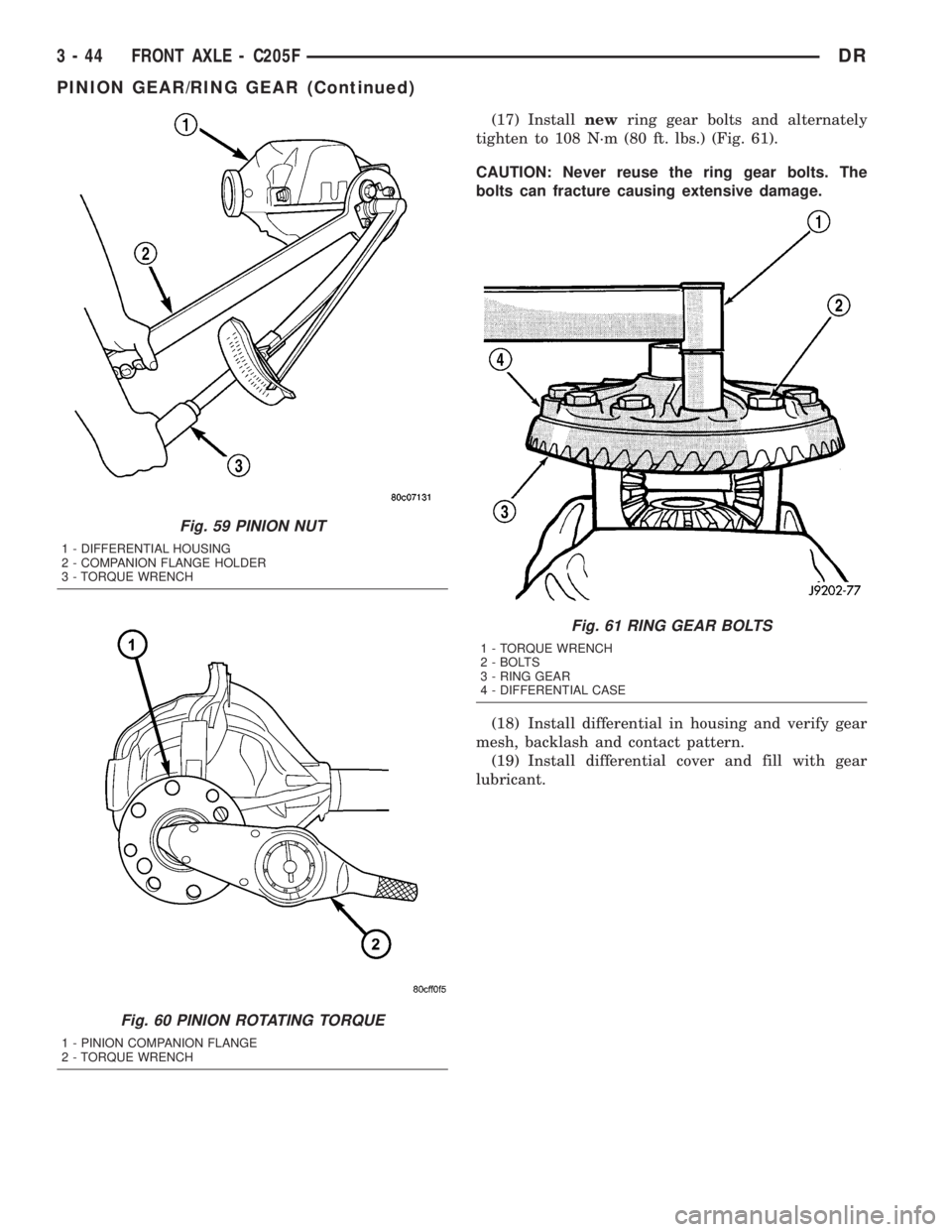
(17) Installnewring gear bolts and alternately
tighten to 108 N´m (80 ft. lbs.) (Fig. 61).
CAUTION: Never reuse the ring gear bolts. The
bolts can fracture causing extensive damage.
(18) Install differential in housing and verify gear
mesh, backlash and contact pattern.
(19) Install differential cover and fill with gear
lubricant.
Fig. 59 PINION NUT
1 - DIFFERENTIAL HOUSING
2 - COMPANION FLANGE HOLDER
3 - TORQUE WRENCH
Fig. 60 PINION ROTATING TORQUE
1 - PINION COMPANION FLANGE
2 - TORQUE WRENCH
Fig. 61 RING GEAR BOLTS
1 - TORQUE WRENCH
2 - BOLTS
3 - RING GEAR
4 - DIFFERENTIAL CASE
3 - 44 FRONT AXLE - C205FDR
PINION GEAR/RING GEAR (Continued)
Page 121 of 2895

Condition Possible Causes Correction
Gear Teeth Broke 1. Overloading. 1. Replace gears. Examine other
gears and bearings for possible
damage.
2. Erratic clutch operation. 2. Replace gears and examine the
remaining parts for damage. Avoid
erratic clutch operation.
3. Ice-spotted pavement. 3. Replace gears and examine
remaining parts for damage.
4. Improper adjustments. 4. Replace gears and examine
remaining parts for damage. Ensure
ring gear backlash is correct.
Axle Noise 1. Insufficient lubricant. 1. Fill differential with the correct
fluid type and quantity.
2. Improper ring gear and pinion
adjustment.2. Check ring gear and pinion
contact pattern.
3. Unmatched ring gear and pinion. 3. Replace gears with a matched
ring gear and pinion.
4. Worn teeth on ring gear and/or
pinion.4. Replace ring gear and pinion.
5. Loose pinion bearings. 5. Adjust pinion bearing pre-load.
6. Loose differential bearings. 6. Adjust differential bearing
pre-load.
7. Mis-aligned or sprung ring gear. 7. Measure ring gear run-out.
Replace components as necessary.
8. Loose differential bearing cap
bolts.8. Inspect differential components
and replace as necessary. Ensure
that the bearing caps are torqued
tot he proper specification.
9. Housing not machined properly. 9. Replace housing.
REMOVAL
(1) Remove wheels and tires.
(2) Remove brake calipers and rotors.
(3) Disconnect ABS wheel speed sensors.
(4) Disconnect axle vent hose.
(5) Remove front propeller shaft.
(6) Disconnect stabilizer bar links at the axle
brackets.
(7) Disconnect shock absorbers from axle brackets.
(8) Disconnect track bar from the axle bracket.
(9) Disconnect tie rod and drag link from the steer-
ing knuckles.
(10) Position suitable lifting device under the axle
assembly.
(11) Secure axle to lifting device.
(12) Mark suspension alignment cams for installa-
tion reference.
(13) Disconnect upper and lower suspension arms
from the axle bracket.(14) Lower the axle. The coil springs will drop
with the axle.
(15) Remove the coil springs from the axle bracket.
INSTALLATION
CAUTION: Suspension components with rubber
bushings should be tightened with the weight of the
vehicle on the suspension, at normal height. If
springs are not at their normal ride position, vehicle
ride comfort could be affected and premature bush-
ing wear may occur. Rubber bushings must never
be lubricated.
(1) Support the axle on a suitable lifting device.
(2) Secure axle to lifting device.
(3) Position the axle under the vehicle.
(4) Install springs, retainer clip and bolts.
(5) Raise axle and align it with the spring pads.
3 - 48 FRONT AXLE - 9 1/4 AADR
FRONT AXLE - 9 1/4 AA (Continued)
Page 123 of 2895
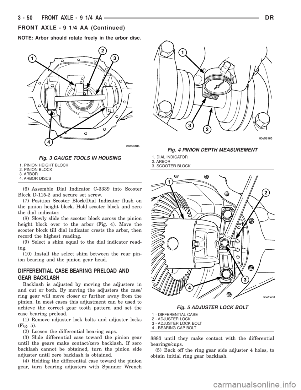
NOTE: Arbor should rotate freely in the arbor disc.
(6) Assemble Dial Indicator C-3339 into Scooter
Block D-115-2 and secure set screw.
(7) Position Scooter Block/Dial Indicator flush on
the pinion height block. Hold scooter block and zero
the dial indicator.
(8) Slowly slide the scooter block across the pinion
height block over to the arbor (Fig. 4). Move the
scooter block till dial indicator crests the arbor, then
record the highest reading.
(9) Select a shim equal to the dial indicator read-
ing.
(10) Install the select shim between the rear pin-
ion bearing and the pinion gear head.
DIFFERENTIAL CASE BEARING PRELOAD AND
GEAR BACKLASH
Backlash is adjusted by moving the adjusters in
and out or both. By moving the adjusters the case/
ring gear will move closer or further away from the
pinion. In most cases this adjustment can be used to
achieve the correct gear tooth pattern and set the
case bearing preload.
(1) Remove adjuster lock bolts and adjuster locks
(Fig. 5).
(2) Loosen the differential bearing caps.
(3) Slide differential case toward the pinion gear
until the gears make contact/zero backlash. If zero
backlash cannot be obtained, turn the pinion side
adjuster until zero backlash is obtained.
(4) Holding the differential case toward the pinion
gear, turn bearing adjusters with Spanner Wrench8883 until they make contact with the differential
bearings/cups.
(5) Back off the ring gear side adjuster 4 holes, to
obtain initial ring gear backlash.
Fig. 3 GAUGE TOOLS IN HOUSING
1. PINION HEIGHT BLOCK
2. PINION BLOCK
3. ARBOR
4. ARBOR DISCS
Fig. 4 PINION DEPTH MEASUREMENT
1. DIAL INDICATOR
2. ARBOR
3. SCOOTER BLOCK
Fig. 5 ADJUSTER LOCK BOLT
1 - DIFFERENTIAL CASE
2 - ADJUSTER LOCK
3 - ADJUSTER LOCK BOLT
4 - BEARING CAP BOLT
3 - 50 FRONT AXLE - 9 1/4 AADR
FRONT AXLE - 9 1/4 AA (Continued)