2003 DODGE RAM bolt pattern
[x] Cancel search: bolt patternPage 2191 of 2895

INPUT SHAFT END PLAY CHECK
NOTE: Overdrive unit must be installed in order to
correctly measure the input shaft end-play.
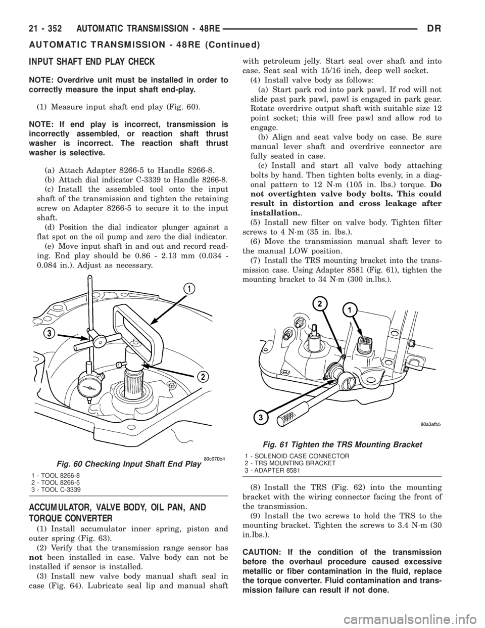
(1) Measure input shaft end play (Fig. 60).
NOTE: If end play is incorrect, transmission is
incorrectly assembled, or reaction shaft thrust
washer is incorrect. The reaction shaft thrust
washer is selective.
(a) Attach Adapter 8266-5 to Handle 8266-8.
(b)
Attach dial indicator C-3339 to Handle 8266-8.
(c) Install the assembled tool onto the input
shaft of the transmission and tighten the retaining
screw on Adapter 8266-5 to secure it to the input
shaft.
(d)
Position the dial indicator plunger against a
flat spot on the oil pump and zero the dial indicator.
(e) Move input shaft in and out and record read-
ing. End play should be 0.86 - 2.13 mm (0.034 -
0.084 in.). Adjust as necessary.
ACCUMULATOR, VALVE BODY, OIL PAN, AND
TORQUE CONVERTER
(1) Install accumulator inner spring, piston and
outer spring (Fig. 63).
(2) Verify that the transmission range sensor has
notbeen installed in case. Valve body can not be
installed if sensor is installed.
(3) Install new valve body manual shaft seal in
case (Fig. 64). Lubricate seal lip and manual shaftwith petroleum jelly. Start seal over shaft and into
case. Seat seal with 15/16 inch, deep well socket.
(4) Install valve body as follows:
(a) Start park rod into park pawl. If rod will not
slide past park pawl, pawl is engaged in park gear.
Rotate overdrive output shaft with suitable size 12
point socket; this will free pawl and allow rod to
engage.
(b) Align and seat valve body on case. Be sure
manual lever shaft and overdrive connector are
fully seated in case.
(c) Install and start all valve body attaching
bolts by hand. Then tighten bolts evenly, in a diag-
onal pattern to 12 N´m (105 in. lbs.) torque.Do
not overtighten valve body bolts. This could
result in distortion and cross leakage after
installation..
(5) Install new filter on valve body. Tighten filter
screws to 4 N´m (35 in. lbs.).
(6) Move the transmission manual shaft lever to
the manual LOW position.
(7)
Install the TRS mounting bracket into the trans-
mission case. Using Adapter 8581 (Fig. 61), tighten the
mounting bracket to 34 N´m (300 in.lbs.).
(8) Install the TRS (Fig. 62) into the mounting
bracket with the wiring connector facing the front of
the transmission.
(9) Install the two screws to hold the TRS to the
mounting bracket. Tighten the screws to 3.4 N´m (30
in.lbs.).
CAUTION: If the condition of the transmission
before the overhaul procedure caused excessive
metallic or fiber contamination in the fluid, replace
the torque converter. Fluid contamination and trans-
mission failure can result if not done.
Fig. 60 Checking Input Shaft End Play
1 - TOOL 8266-8
2 - TOOL 8266-5
3 - TOOL C-3339
Fig. 61 Tighten the TRS Mounting Bracket
1 - SOLENOID CASE CONNECTOR
2 - TRS MOUNTING BRACKET
3 - ADAPTER 8581
21 - 352 AUTOMATIC TRANSMISSION - 48REDR
AUTOMATIC TRANSMISSION - 48RE (Continued)
Page 2254 of 2895

ment Tool 6227-2. Overdrive unit cannot be installed
if splines are not aligned. If splines have rotated out
of alignment, unit will have to be disassembled to
realign splines.
(9)
Carefully slide Alignment Tool 6227-2 out of over-
drive planetary gear and overrunning clutch splines.
(10) Raise overdrive unit and carefully slide it
straight onto intermediate shaft. Insert park rod into
park lock reaction plug at same time. Avoid tilting
overdrive during installation as this could cause
planetary gear and overrunning clutch splines to
rotate out of alignment. If this occurs, it will be nec-
essary to remove and disassemble overdrive unit to
realign splines.
(11) Work overdrive unit forward on intermediate
shaft until seated against transmission case.
(12) Install bolts attaching overdrive unit to trans-
mission unit. Tighten bolts in diagonal pattern to 34
N´m (25 ft-lbs).
(13) Connect the transmission speed sensor and
overdrive wiring connectors.
(14) Install the transfer case, if equipped.
(15) Align and install rear propeller shaft, if nec-
essary. (Refer to 3 - DIFFERENTIAL & DRIVELINE/
PROPELLER SHAFT/PROPELLER SHAFT -
INSTALLATION)
OVERRUNNING CLUTCH
CAM/OVERDRIVE PISTON
RETAINER
DESCRIPTION
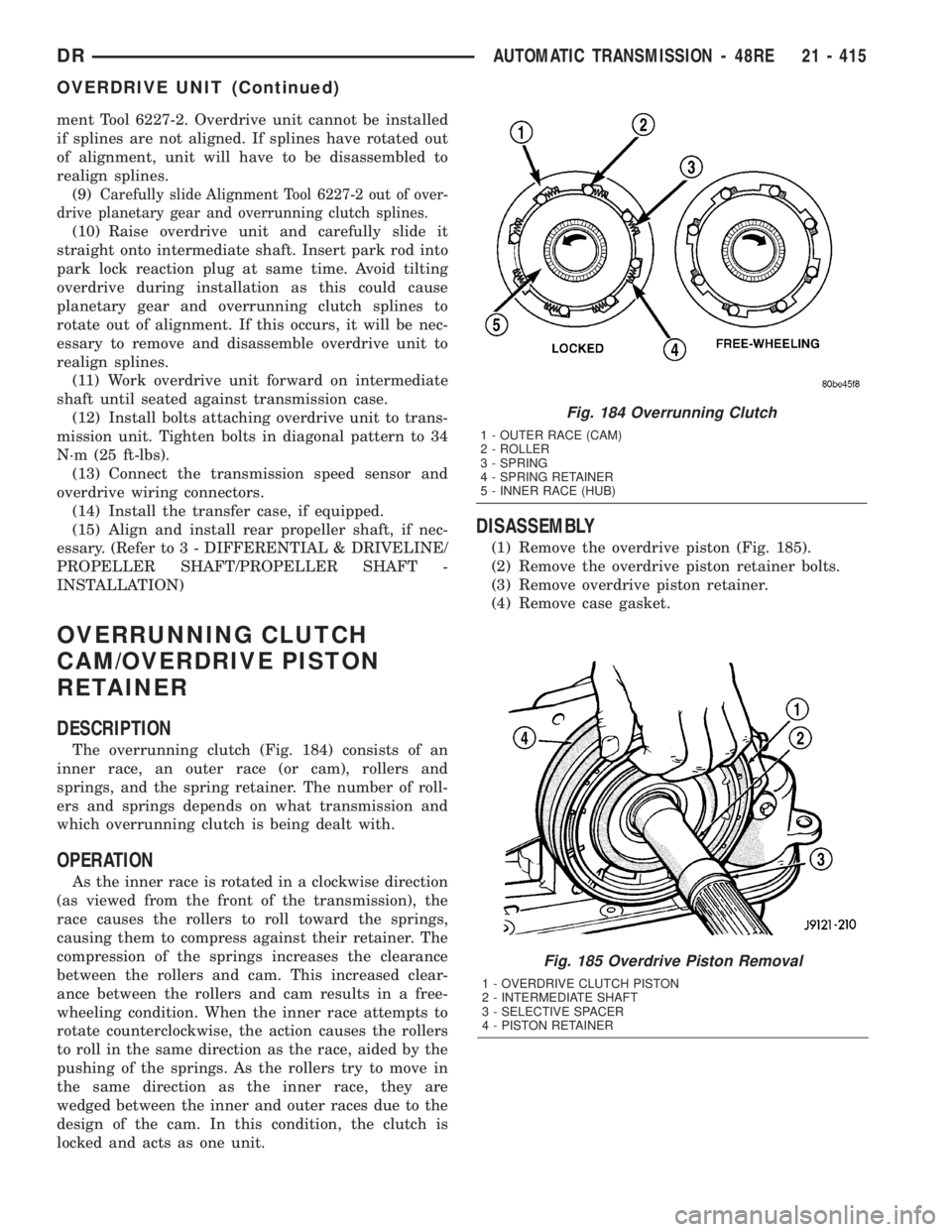
The overrunning clutch (Fig. 184) consists of an
inner race, an outer race (or cam), rollers and
springs, and the spring retainer. The number of roll-
ers and springs depends on what transmission and
which overrunning clutch is being dealt with.
OPERATION
As the inner race is rotated in a clockwise direction
(as viewed from the front of the transmission), the
race causes the rollers to roll toward the springs,
causing them to compress against their retainer. The
compression of the springs increases the clearance
between the rollers and cam. This increased clear-
ance between the rollers and cam results in a free-
wheeling condition. When the inner race attempts to
rotate counterclockwise, the action causes the rollers
to roll in the same direction as the race, aided by the
pushing of the springs. As the rollers try to move in
the same direction as the inner race, they are
wedged between the inner and outer races due to the
design of the cam. In this condition, the clutch is
locked and acts as one unit.
DISASSEMBLY
(1) Remove the overdrive piston (Fig. 185).
(2) Remove the overdrive piston retainer bolts.
(3) Remove overdrive piston retainer.
(4) Remove case gasket.
Fig. 185 Overdrive Piston Removal
1 - OVERDRIVE CLUTCH PISTON
2 - INTERMEDIATE SHAFT
3 - SELECTIVE SPACER
4 - PISTON RETAINER
Fig. 184 Overrunning Clutch
1 - OUTER RACE (CAM)
2 - ROLLER
3 - SPRING
4 - SPRING RETAINER
5 - INNER RACE (HUB)
DRAUTOMATIC TRANSMISSION - 48RE 21 - 415
OVERDRIVE UNIT (Continued)
Page 2570 of 2895

WHEELS
DESCRIPTION
Original equipment wheels are designed for the
specified Maximum Vehicle Capacity.
All models use steel or aluminum drop center
wheels.
Aluminum wheels require special balance weights
and alignment equipment.
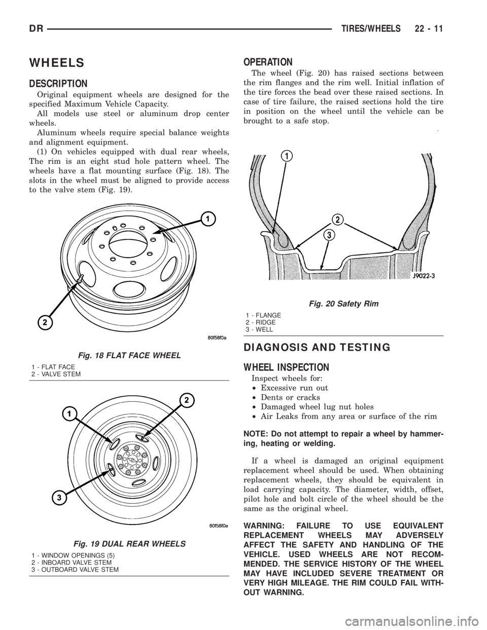
(1) On vehicles equipped with dual rear wheels,
The rim is an eight stud hole pattern wheel. The
wheels have a flat mounting surface (Fig. 18). The
slots in the wheel must be aligned to provide access
to the valve stem (Fig. 19).
OPERATION
The wheel (Fig. 20) has raised sections between
the rim flanges and the rim well. Initial inflation of
the tire forces the bead over these raised sections. In
case of tire failure, the raised sections hold the tire
in position on the wheel until the vehicle can be
brought to a safe stop.
DIAGNOSIS AND TESTING
WHEEL INSPECTION
Inspect wheels for:
²Excessive run out
²Dents or cracks
²Damaged wheel lug nut holes
²Air Leaks from any area or surface of the rim
NOTE: Do not attempt to repair a wheel by hammer-
ing, heating or welding.
If a wheel is damaged an original equipment
replacement wheel should be used. When obtaining
replacement wheels, they should be equivalent in
load carrying capacity. The diameter, width, offset,
pilot hole and bolt circle of the wheel should be the
same as the original wheel.
WARNING: FAILURE TO USE EQUIVALENT
REPLACEMENT WHEELS MAY ADVERSELY
AFFECT THE SAFETY AND HANDLING OF THE
VEHICLE. USED WHEELS ARE NOT RECOM-
MENDED. THE SERVICE HISTORY OF THE WHEEL
MAY HAVE INCLUDED SEVERE TREATMENT OR
VERY HIGH MILEAGE. THE RIM COULD FAIL WITH-
OUT WARNING.
Fig. 18 FLAT FACE WHEEL
1 - FLAT FACE
2 - VALVE STEM
Fig. 19 DUAL REAR WHEELS
1 - WINDOW OPENINGS (5)
2 - INBOARD VALVE STEM
3 - OUTBOARD VALVE STEM
Fig. 20 Safety Rim
1 - FLANGE
2 - RIDGE
3 - WELL
DRTIRES/WHEELS 22 - 11
Page 2571 of 2895

STANDARD PROCEDURE
STANDARD PROCEDURE - WHEEL
REPLACEMENT
The wheel studs and nuts are designed for specific
applications. They must be replaced with equivalent
parts. Do not use replacement parts of lesser quality
or a substitute design. All aluminum and some steel
wheels have wheel stud nuts which feature an
enlarged nose. This enlarged nose is necessary to
ensure proper retention of the aluminum wheels.
NOTE: Do not use chrome plated lug nuts with
chrome plated wheels.
Before installing the wheel, be sure to remove any
build up of corrosion on the wheel mounting surfaces.
Ensure wheels are installed with good metal-to-metal
contact. Improper installation could cause loosening
of wheel nuts (Fig. 21). This could affect the safety
and handling of your vehicle.
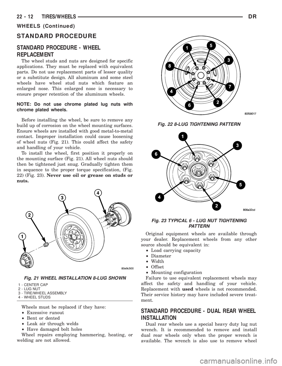
To install the wheel, first position it properly on
the mounting surface (Fig. 21). All wheel nuts should
then be tightened just snug. Gradually tighten them
in sequence to the proper torque specification, (Fig.
22) (Fig. 23).Never use oil or grease on studs or
nuts.
Wheels must be replaced if they have:
²Excessive runout
²Bent or dented
²Leak air through welds
²Have damaged bolt holes
Wheel repairs employing hammering, heating, or
welding are not allowed.Original equipment wheels are available through
your dealer. Replacement wheels from any other
source should be equivalent in:
²Load carrying capacity
²Diameter
²Width
²Offset
²Mounting configuration
Failure to use equivalent replacement wheels may
affect the safety and handling of your vehicle.
Replacement withusedwheels is not recommended.
Their service history may have included severe treat-
ment.
STANDARD PROCEDURE - DUAL REAR WHEEL
INSTALLATION
Dual rear wheels use a special heavy duty lug nut
wrench. It is recommended to remove and install
dual rear wheels only when the proper wrench is
available. The wrench is also use to remove wheel
Fig. 21 WHEEL INSTALLATION 8-LUG SHOWN
1 - CENTER CAP
2 - LUG NUT
3 - TIRE/WHEEL ASSEMBLY
4 - WHEEL STUDS
Fig. 22 8-LUG TIGHTENING PATTERN
Fig. 23 TYPICAL 6 - LUG NUT TIGHTENING
PATTERN
22 - 12 TIRES/WHEELSDR
WHEELS (Continued)