2003 DODGE RAM width
[x] Cancel search: widthPage 260 of 2895

(6) Install the right cable to the front cable.
(7) Adjust the brake cable at the equalizer and
using the adjuster nut.
INSTALLATION - LEFT REAR CABLE
(1) Install the brake cable to the brake lever (Fig.
61).
(2) Install the brake cable to the frame bracket.
(3) Install the left brake cable to the equalizer.
(4) Adjust the brake cable at the equalizer and
adjuster nut.
SHOES
REMOVAL
(1) Raise and support the vehicle.
(2) Remove the tire and wheel assembly.
(3) Remove the disc brake caliper,(Refer to 5 -
BRAKES/HYDRAULIC/MECHANICAL/DISC
BRAKE CALIPERS - REMOVAL).
(4) Remove the disc brake rotor, (Refer to 5 -
BRAKES/HYDRAULIC/MECHANICAL/ROTORS -
REMOVAL).
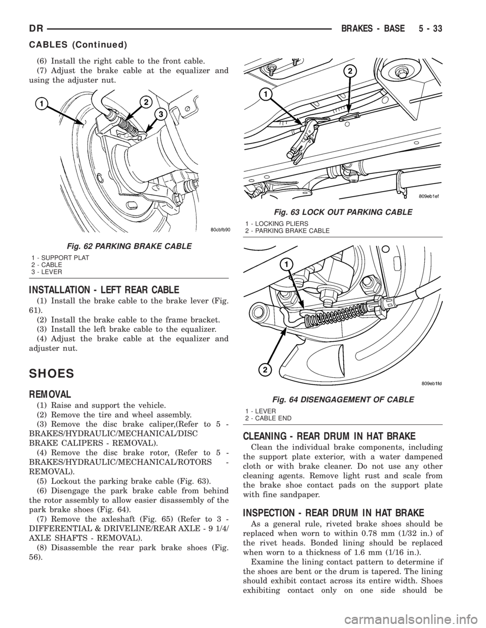
(5) Lockout the parking brake cable (Fig. 63).
(6) Disengage the park brake cable from behind
the rotor assembly to allow easier disassembly of the
park brake shoes (Fig. 64).
(7) Remove the axleshaft (Fig. 65) (Refer to 3 -
DIFFERENTIAL & DRIVELINE/REAR AXLE - 9 1/4/
AXLE SHAFTS - REMOVAL).
(8) Disassemble the rear park brake shoes (Fig.
56).
CLEANING - REAR DRUM IN HAT BRAKE
Clean the individual brake components, including
the support plate exterior, with a water dampened
cloth or with brake cleaner. Do not use any other
cleaning agents. Remove light rust and scale from
the brake shoe contact pads on the support plate
with fine sandpaper.
INSPECTION - REAR DRUM IN HAT BRAKE
As a general rule, riveted brake shoes should be
replaced when worn to within 0.78 mm (1/32 in.) of
the rivet heads. Bonded lining should be replaced
when worn to a thickness of 1.6 mm (1/16 in.).
Examine the lining contact pattern to determine if
the shoes are bent or the drum is tapered. The lining
should exhibit contact across its entire width. Shoes
exhibiting contact only on one side should be
Fig. 62 PARKING BRAKE CABLE
1 - SUPPORT PLAT
2 - CABLE
3 - LEVER
Fig. 63 LOCK OUT PARKING CABLE
1 - LOCKING PLIERS
2 - PARKING BRAKE CABLE
Fig. 64 DISENGAGEMENT OF CABLE
1 - LEVER
2 - CABLE END
DRBRAKES - BASE 5 - 33
CABLES (Continued)
Page 290 of 2895

DESCRIPTION - HOSE CLAMPS
The cooling system utilizes spring type hose
clamps. If a spring type clamp replacement is neces-
sary, replace with the original Mopartequipment
spring type clamp.
CAUTION: A number or letter is stamped into the
tongue of constant tension clamps. If replacement
is necessary, use only a original equipment clamp
with matching number or letter and ensure the
clamp has the same size width (Fig. 4).
OPERATION
OPERATIONÐCOOLING SYSTEM
The cooling system regulates engine operating tem-
perature. It allows the engine to reach normal oper-
ating temperature as quickly as possible. It also
maintains normal operating temperature and pre-
vents overheating.
The cooling system also provides a means of heat-
ing the passenger compartment and cooling the auto-
matic transmission fluid (if equipped). The cooling
Fig. 2 ENGINE COOLING SYSTEM FLOW - 5.9L
1 - HEATER
2 - BYPASS*3 - CROSSFLOW RADIATOR
4 - THERMOSTAT LOCATION
DRCOOLING 7 - 3
COOLING (Continued)
Page 309 of 2895

ACCESSORY DRIVE
TABLE OF CONTENTS
page page
BELT TENSIONERS - 3.7L / 4.7L
DESCRIPTION.........................22
OPERATION...........................22
REMOVAL.............................22
INSTALLATION.........................23
BELT TENSIONERS - 5.9L
DESCRIPTION.........................23
OPERATION...........................23
REMOVAL.............................23
INSTALLATION.........................24
BELT TENSIONERS - 5.9L DIESEL
DESCRIPTION.........................24
OPERATION...........................24
REMOVAL.............................25
INSTALLATION.........................25DRIVE BELTS - 3.7L / 4.7L
DIAGNOSIS AND TESTING - ACCESSORY
DRIVE BELT.........................25
REMOVAL.............................27
INSTALLATION.........................27
DRIVE BELTS - 5.9L
DIAGNOSIS AND TESTING - ACCESSORY
DRIVE BELT.........................28
REMOVAL.............................30
INSTALLATION.........................31
DRIVE BELTS - 5.9L DIESEL
DIAGNOSIS AND TESTINGÐACCESSORY
DRIVE BELT.........................31
REMOVAL.............................34
INSTALLATION.........................34
BELT TENSIONERS - 3.7L /
4.7L
DESCRIPTION
Correct drive belt tension is required to ensure
optimum performance of the belt driven engine acces-
sories. If specified tension is not maintained, belt
slippage may cause; engine overheating, lack of
power steering assist, loss of air conditioning capac-
ity, reduced generator output rate, and greatly
reduced belt life.
It is not necessary to adjust belt tension on the
3.7L or 4.7L engine. These engines are equipped with
an automatic belt tensioner (Fig. 1). The tensioner
maintains correct belt tension at all times. Due to
use of this belt tensioner, do not attempt to use a belt
tension gauge on 3.7L or 4.7L engines.
OPERATION
The automatic belt tensioner maintains belt ten-
sion by using internal spring pressure, a pivoting
arm and pulley to press against the drive belt.
REMOVAL
On 3.7L and 4.7L engines, the tensioner is
equipped with an indexing tang on back of ten-
sioner and an indexing stop on tensioner hous-
ing. If a new belt is being installed, tang must
be within approximately 24 mm (.94 inches) ofindexing stop. Belt is considered new if it has
been used 15 minutes or less.
If the above specification cannot be met, check for:
²The wrong belt being installed (incorrect length/
width)
²Worn bearings on an engine accessory (A/C com-
pressor, power steering pump, water pump, idler pul-
ley or generator)
²A pulley on an engine accessory being loose
²Misalignment of an engine accessory
²Belt incorrectly routed.
Fig. 1 AUTOMATIC BELT TENSIONER
1 - AUTOMATIC TENSIONER ASSEMBLY
7 - 22 ACCESSORY DRIVEDR
Page 331 of 2895

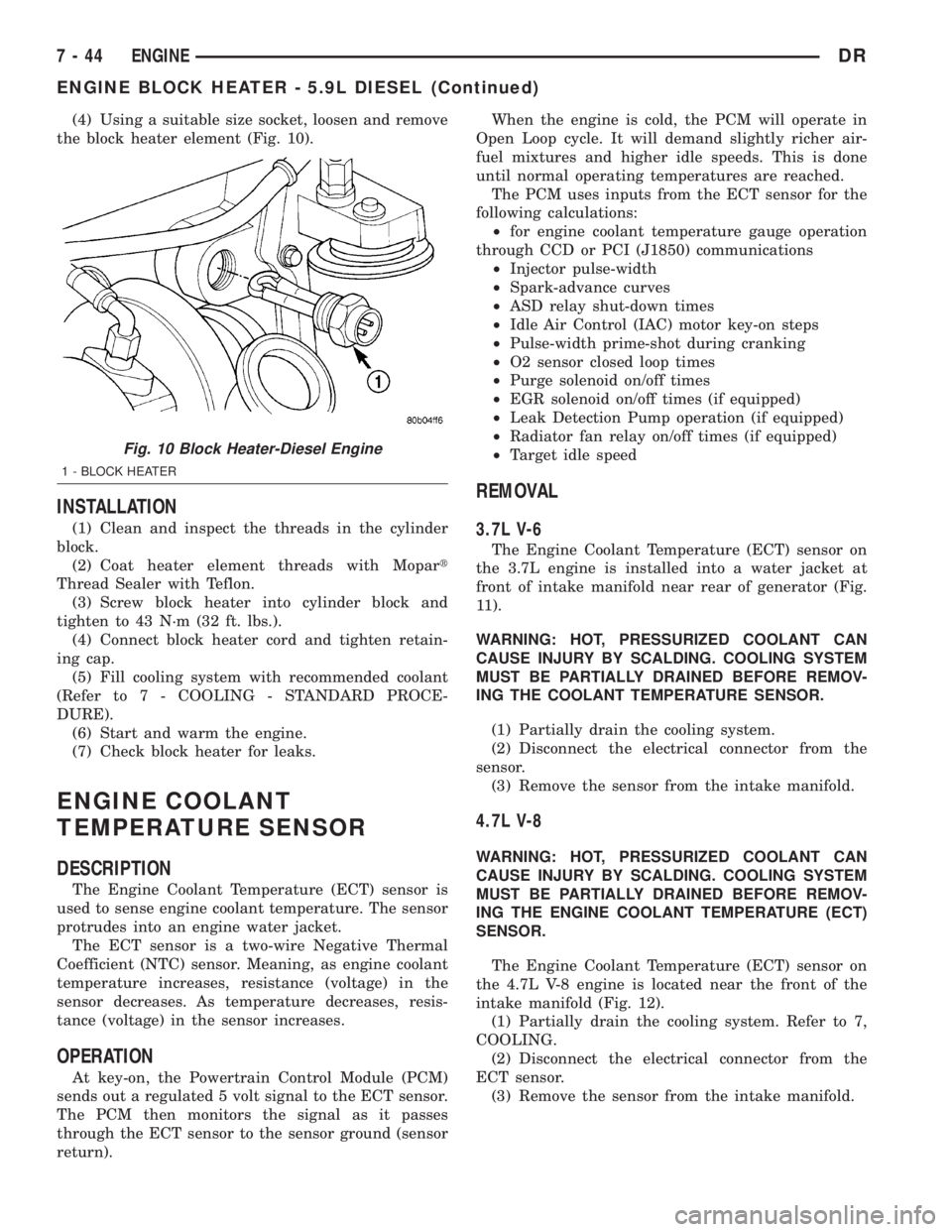
(4) Using a suitable size socket, loosen and remove
the block heater element (Fig. 10).
INSTALLATION
(1) Clean and inspect the threads in the cylinder
block.
(2) Coat heater element threads with Mopart
Thread Sealer with Teflon.
(3) Screw block heater into cylinder block and
tighten to 43 N´m (32 ft. lbs.).
(4) Connect block heater cord and tighten retain-
ing cap.
(5) Fill cooling system with recommended coolant
(Refer to 7 - COOLING - STANDARD PROCE-
DURE).
(6) Start and warm the engine.
(7) Check block heater for leaks.
ENGINE COOLANT
TEMPERATURE SENSOR
DESCRIPTION
The Engine Coolant Temperature (ECT) sensor is
used to sense engine coolant temperature. The sensor
protrudes into an engine water jacket.
The ECT sensor is a two-wire Negative Thermal
Coefficient (NTC) sensor. Meaning, as engine coolant
temperature increases, resistance (voltage) in the
sensor decreases. As temperature decreases, resis-
tance (voltage) in the sensor increases.
OPERATION
At key-on, the Powertrain Control Module (PCM)
sends out a regulated 5 volt signal to the ECT sensor.
The PCM then monitors the signal as it passes
through the ECT sensor to the sensor ground (sensor
return).When the engine is cold, the PCM will operate in
Open Loop cycle. It will demand slightly richer air-
fuel mixtures and higher idle speeds. This is done
until normal operating temperatures are reached.
The PCM uses inputs from the ECT sensor for the
following calculations:
²for engine coolant temperature gauge operation
through CCD or PCI (J1850) communications
²Injector pulse-width
²Spark-advance curves
²ASD relay shut-down times
²Idle Air Control (IAC) motor key-on steps
²Pulse-width prime-shot during cranking
²O2 sensor closed loop times
²Purge solenoid on/off times
²EGR solenoid on/off times (if equipped)
²Leak Detection Pump operation (if equipped)
²Radiator fan relay on/off times (if equipped)
²Target idle speed
REMOVAL
3.7L V-6
The Engine Coolant Temperature (ECT) sensor on
the 3.7L engine is installed into a water jacket at
front of intake manifold near rear of generator (Fig.
11).
WARNING: HOT, PRESSURIZED COOLANT CAN
CAUSE INJURY BY SCALDING. COOLING SYSTEM
MUST BE PARTIALLY DRAINED BEFORE REMOV-
ING THE COOLANT TEMPERATURE SENSOR.
(1) Partially drain the cooling system.
(2) Disconnect the electrical connector from the
sensor.
(3) Remove the sensor from the intake manifold.
4.7L V-8
WARNING: HOT, PRESSURIZED COOLANT CAN
CAUSE INJURY BY SCALDING. COOLING SYSTEM
MUST BE PARTIALLY DRAINED BEFORE REMOV-
ING THE ENGINE COOLANT TEMPERATURE (ECT)
SENSOR.
The Engine Coolant Temperature (ECT) sensor on
the 4.7L V-8 engine is located near the front of the
intake manifold (Fig. 12).
(1) Partially drain the cooling system. Refer to 7,
COOLING.
(2) Disconnect the electrical connector from the
ECT sensor.
(3) Remove the sensor from the intake manifold.
Fig. 10 Block Heater-Diesel Engine
1 - BLOCK HEATER
7 - 44 ENGINEDR
ENGINE BLOCK HEATER - 5.9L DIESEL (Continued)
Page 336 of 2895

WARNING: CONSTANT TENSION HOSE CLAMPS
ARE USED ON MOST COOLING SYSTEM HOSES.
WHEN REMOVING OR INSTALLING, USE ONLY
TOOLS DESIGNED FOR SERVICING THIS TYPE OF
CLAMP. ALWAYS WEAR SAFETY GLASSES WHEN
SERVICING CONSTANT TENSION CLAMPS.
CAUTION: A number or letter is stamped into the
tongue of the constant tension clamps (Fig. 21). If
replacement is necessary, use only an original
equipment clamp with a matching number, letter
and width.
(7) Remove the radiator upper hose clamp and
upper hose at the thermostat housing.
(8) Position the wiring harness (behind thermostat
housing) to gain access to the thermostat housing.
(9) Remove the thermostat housing mounting
bolts, thermostat housing, gasket and thermostat
(Fig. 22). Discard old gasket.
INSTALLATION
(1) Clean the mating areas of the intake manifold
and thermostat housing.
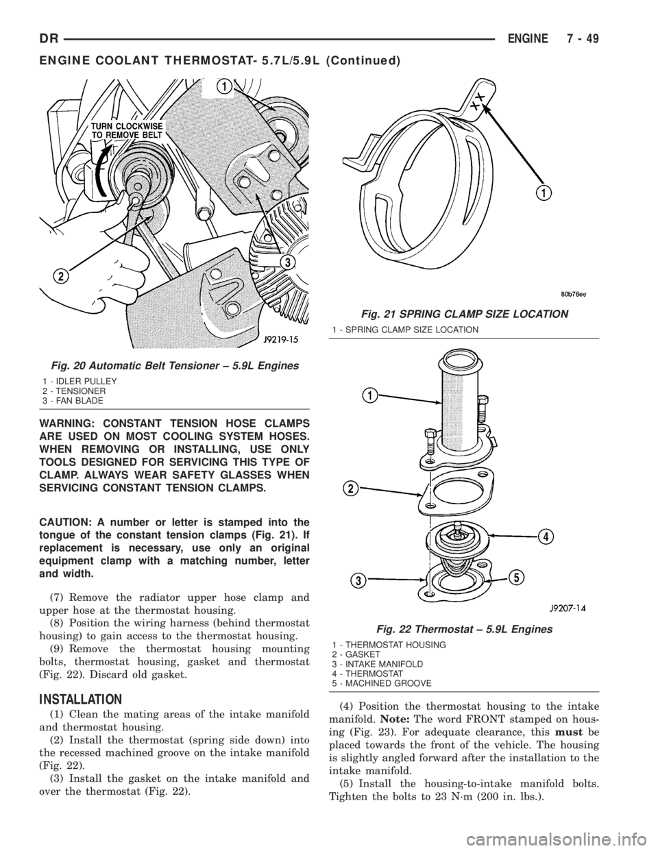
(2) Install the thermostat (spring side down) into
the recessed machined groove on the intake manifold
(Fig. 22).
(3) Install the gasket on the intake manifold and
over the thermostat (Fig. 22).(4) Position the thermostat housing to the intake
manifold.Note:The word FRONT stamped on hous-
ing (Fig. 23). For adequate clearance, thismustbe
placed towards the front of the vehicle. The housing
is slightly angled forward after the installation to the
intake manifold.
(5) Install the housing-to-intake manifold bolts.
Tighten the bolts to 23 N´m (200 in. lbs.).
Fig. 20 Automatic Belt Tensioner ± 5.9L Engines
1 - IDLER PULLEY
2 - TENSIONER
3 - FAN BLADE
Fig. 21 SPRING CLAMP SIZE LOCATION
1 - SPRING CLAMP SIZE LOCATION
Fig. 22 Thermostat ± 5.9L Engines
1 - THERMOSTAT HOUSING
2 - GASKET
3 - INTAKE MANIFOLD
4 - THERMOSTAT
5 - MACHINED GROOVE
DRENGINE 7 - 49
ENGINE COOLANT THERMOSTAT- 5.7L/5.9L (Continued)
Page 344 of 2895

DIAGNOSIS AND TESTINGÐRADIATOR
COOLANT FLOW
Use the following procedure to determine if coolant
is flowing through the cooling system.
(1) Idle engine until operating temperature is
reached. If the upper radiator hose is warm to the
touch, the thermostat is opening and coolant is flow-
ing to the radiator.
WARNING: HOT, PRESSURIZED COOLANT CAN
CAUSE INJURY BY SCALDING. USING A RAG TO
COVER THE RADIATOR PRESSURE CAP, OPEN
RADIATOR CAP SLOWLY TO THE FIRST STOP. THIS
WILL ALLOW ANY BUILT-UP PRESSURE TO VENT
TO THE RESERVE/OVERFLOW TANK. AFTER PRES-
SURE BUILD-UP HAS BEEN RELEASED, REMOVE
CAP FROM FILLER NECK.
(2) Drain a small amount of coolant from the radi-
ator until the ends of the radiator tubes are visible
through the filler neck. Idle the engine at normal
operating temperature. If coolant is flowing past the
exposed tubes, the coolant is circulating.
REMOVAL
(1) Disconnect battery negative cables.WARNING: DO NOT REMOVE THE CYLINDER
BLOCK DRAIN PLUGS OR LOOSEN THE RADIATOR
DRAINCOCK WITH THE SYSTEM HOT AND UNDER
PRESSURE. SERIOUS BURNS FROM THE COOL-
ANT CAN OCCUR.
(2) Drain the cooling system (Refer to 7 - COOL-
ING - STANDARD PROCEDURE).
WARNING: CONSTANT TENSION HOSE CLAMPS
ARE USED ON MOST COOLING SYSTEM HOSES.
WHEN REMOVING OR INSTALLING, USE ONLY
TOOLS DESIGNED FOR SERVICING THIS TYPE OF
CLAMP. ALWAYS WEAR SAFETY GLASSES WHEN
SERVICING CONSTANT TENSION CLAMPS.
CAUTION: A number or letter is stamped into the
tongue of constant tension clamps. If replacement
is necessary, use only an original equipment clamp
with a matching number or letter and the correct
width.
(3) Remove the hose clamps and hoses from radia-
tor.
(4) Remove the coolant reserve/overflow tank hose
from the radiator filler neck.
(5) Remove the coolant reserve/overflow tank
(5.9L) or the coolant degas container(3.7L/4.7L) from
the fan shroud (pull straight up). The tank slips into
slots on the fan shroud.
(6) Unclip the power steering hoses from the fan
shroud.
(7) Disconnect the electrical connectors at the
windshield washer reservoir tank and remove the
tank.
(8) Remove the fan shroud mounting bolts and pull
up and out of the radiator tank clips (Fig. 33). Posi-
tion shroud rearward over the fan blades towards
engine.
(9) Disconnect the transmission cooler lines from
the transmission cooler, then plug the transmission
lines and cooler to prevent leakage.
(10) Disconnect the power steering lines from the
power steering cooler, then plug the power steering
lines and cooler to prevent leakage.
(11) Remove the two radiator upper mounting
bolts (Fig. 34).
(12) Lift the radiator straight up and out of the
engine compartment. Take care not to damage cool-
ing fins or tubes on the radiator and oil coolers when
removing.
Fig. 32 Radiator Ð Typical
1 - SCREW
2 - SCREW
3 - LOWER MOUNT
4 - RADIATOR
5 - DRAINCOCK
6 -LOWER MOUNT
DRENGINE 7 - 57
RADIATOR (Continued)
Page 352 of 2895

radiator core, cooling system hoses and heater core,
this coolant absorbs the heat generated when the
engine is running. The pump is driven by the engine
crankshaft via a drive belt.
OPERATIONÐWATER PUMP BYPASS
When the thermostat is in the closed position the
bypass gallery is not obstructed allowing 100% flow.
When the thermostat is in the open position the stub
shaft enters the bypass gallery obstructing bypass
coolant flow by 50%. This design allows the coolant
to reach operating temperature quickly when cold,
while adding extra cooling during normal tempera-
ture operation.
REMOVAL
The water pump on 3.7L/4.7L engines is bolted
directly to the engine timing chain case cover.
(1) Disconnect the negative battery cable.
(2) Drain cooling system (Refer to 7 - COOLING -
STANDARD PROCEDURE).
(3) Remove fan/viscous fan drive assembly from
water pump (Fig. 46) (Refer to 7 - COOLING/EN-
GINE/FAN DRIVE VISCOUS CLUTCH - REMOV-
AL). Do not attempt to remove fan/viscous fan drive
assembly from vehicle at this time.
WARNING: CONSTANT TENSION HOSE CLAMPS
ARE USED ON MOST COOLING SYSTEM HOSES.WHEN REMOVING OR INSTALLING, USE ONLY
TOOLS DESIGNED FOR SERVICING THIS TYPE OF
CLAMP. ALWAYS WEAR SAFETY GLASSES WHEN
SERVICING CONSTANT TENSION CLAMPS.
CAUTION: A number or letter is stamped into the
tongue of constant tension clamps. If replacement
is necessary, use only an original equipment clamp
with matching number or letter and width.
(4) If the water pump is being replaced, do not
unbolt the fan blade assembly from the thermal vis-
cous fan drive.
(5) Remove the radiator fan (Refer to 7 - COOL-
ING/ENGINE/RADIATOR FAN - REMOVAL).
(6) Remove accessory drive belt (Fig. 47) (Refer to
7 - COOLING/ACCESSORY DRIVE/DRIVE BELTS -
REMOVAL).
(7) Remove the lower radiator hose clamp and
remove the lower hose at the water pump.
(8) Remove the water pump mounting bolts.
Fig. 44 Water Pump and Timing Chain Cover
1 - INTEGRAL WATER PUMP PULLEY
2 - TIMING CHAIN COVER
3 - THERMOSTAT HOUSING
4 - HEATER HOSE FITTINGS
5 - WATER PUMP
Fig. 45 Water/Coolant Bypass Flow and Thermostat
1 - FROM HEATER AND DEGAS CONTAINER
2 - FROM RADIATOR
3 - TO WATER PUMP
4 - ENGINE BYPASS
5 - THERMOSTAT
DRENGINE 7 - 65
WATER PUMP - 3.7L/4.7L (Continued)
Page 357 of 2895

CAUTION: A number or letter is stamped into the
tongue of the constant tension clamps. If replace-
ment is necessary, use only an original equipment
clamp with a matching number or letter and width.
(2) Loosen both of the bypass hose clamps and
position them to the center of the hose.
(3) Removethe hose from the vehicle.
INSTALLATION
INSTALLATION - WATER PUMP BYPASS HOSE
WITH AIR CONDITIONING
(1) Position the bypass hose clamps to the center
of the bypass hose.
(2) Install the bypass hose to the engine.
(3) Secure both of the hose clamps.
(4) Install the generator-A/C mounting bracket
assembly to the engine. Tighten bolt number 1 (Fig.
53) to 41 N´m (30 ft. lbs.). Tighten bolt number 2
(Fig. 53) to 28 N´m (20 ft. lbs.). Tighten bracket
mounting bolts (Fig. 53) (Fig. 53) to 40 N´m (30 ft.
lbs.).
(5) Install a new O-ring to the heater hose coolant
return tube. Coat the new O-ring with antifreeze
before installation.
(6) Install the coolant return tube and its mount-
ing bolt to the engine.
(7) Connect the throttle body control cables.
(8) Install the oil dipstick mounting bolt.
(9) Install the idler pulley. Tighten the bolt to 41
N´m (30 ft. lbs.) (Fig. 57).
(10) Install the drive belt (Refer to 7 - COOLING/
ACCESSORY DRIVE/DRIVE BELTS - INSTALLA-
TION).CAUTION: When installing the serpentine accessory
drive belt, the belt must be routed correctly. If not,
the engine may overheat due to the water pump
rotating in the wrong direction (Refer to 7 - COOL-
ING/ACCESSORY DRIVE/DRIVE BELTS - INSTALLA-
TION). The correct belt with the correct length must
be used.
(11) Install the air cleaner assembly.
(12) Install the upper radiator hose to the radiator.
(13) Connect the throttle cable to the clip at the
radiator fan shroud.
(14) Connect the wiring harness to the A/C com-
pressor.
(15) Fill the cooling system (Refer to 7 - COOLING
- STANDARD PROCEDURE).
(16) Start and warm the engine. Check for leaks.
INSTALLATION - WATER PUMP BYPASS HOSE
WITHOUT AIR CONDITIONING
(1) Position the bypass hose clamps to the center
of the bypass hose.
(2) Install the bypass hose tothe engine.
(3) Secure both of the hose clamps.
(4) Fill the cooling system (Refer to 7 - COOLING
- STANDARD PROCEDURE).
(5) Start and warm the engine. Check for leaks.
WATER PUMP - 5.7L
REMOVAL
(1) Disconnect negative battery cable.
(2) Drain coolant.
(3) Remove serpentine belt.
(4) Remove fan clutch assembly.
(5) Remove coolant fill bottle.
Fig. 56 Water Pump Bypass Hose - Typical
1 - WATER PUMP BYPASS HOSE
2 - FAN BLADE ASSEMBLY
3 - VISCOUS FAN DRIVE
4 - WATER PUMP AND PULLEY
Fig. 57 Tensioner Mounting
1 - DOWEL PIN HOLE
2 - TENSIONER MOUNTING BRACKET
7 - 70 ENGINEDR
WATER PUMP INLET TUBE - 5.9L (Continued)