2003 DODGE RAM engine oil capacity
[x] Cancel search: engine oil capacityPage 18 of 2895

FLUID ADDITIVES
DaimlerChrysler strongly recommends against the
addition of any fluids to the transmission, other than
those automatic transmission fluids listed above.
Exceptions to this policy are the use of special dyes
to aid in detecting fluid leaks.
Various ªspecialº additives and supplements exist
that claim to improve shift feel and/or quality. These
additives and others also claim to improve converter
clutch operation and inhibit overheating, oxidation,
varnish, and sludge. These claims have not been sup-
ported to the satisfaction of DaimlerChrysler and
these additivesmust not be used.The use of trans-
mission ªsealersº should also be avoided, since they
may adversely affect the integrity of transmission
seals.
OPERATION - AUTOMATIC TRANSMISSION
FLUID
The automatic transmission fluid is selected based
upon several qualities. The fluid must provide a high
level of protection for the internal components by
providing a lubricating film between adjacent metal
components. The fluid must also be thermally stable
so that it can maintain a consistent viscosity through
a large temperature range. If the viscosity stays con-
stant through the temperature range of operation,
transmission operation and shift feel will remain con-
sistent. Transmission fluid must also be a good con-
ductor of heat. The fluid must absorb heat from the
internal transmission components and transfer that
heat to the transmission case.
FLUID CAPACITIES
SPECIFICATIONS
FLUID CAPACITIES
2DESCRIPTIONSPECIFICATION
FUEL TANK
Short Box (Lt. Duty) 98 L (26 gal.)*
Long Box (Lt. Duty) 132 L (35 gal.)*
ENGINE OIL WITH FILTER
3.7L 4.7 L (5.0 qts.)
4.7L 5.6 L (6.0 qts.)
5.7L 6.6 L (7.0 qts.)
5.9L 4.7 L (5.0 qts.)
8.0L 6.6 L (7.0 qts.)
5.9L DIESEL 10.4 L (11.0 qts.)
2DESCRIPTION SPECIFICATION
COOLING SYSTEM
3.7L 15.4 L (16.2 qts.)**
4.7L 15.4 L (16.2 qts.)**
5.7L 15.4L (16.2 qts.)**
5.9L 15.5 L (16.3 qts.)**
8.0L 24L (24.3 qts.)**
5.9L Diesel Engine 28L (29.5 qts.)**
POWER STEERING
Power steering fluid capacities are dependent on engine/
chassis options as well as steering gear/cooler options.
Depending on type and size of internal cooler, length and
inside diameter of cooler lines, or use of an auxiliary cooler,
these capacities may vary. Refer to 19, Steering for proper
fill and bleed procedures.
AUTOMATIC TRANSMISSION
Service Fill - 46RE 3.8 L (4.0 qts.)
O-haul - 46RE 9-9.5L (19-20 pts.)L
Service Fill - 45RFE/
545RFE4X2 - 5.2 L (11.0 pts.)
4X4 - 6.2 L (13.0 pts.)
O-haul - 45RFE/545RFE 14-16 L (29-33 pts.)L
LDry fill capacity Depending on type and size of internal
cooler, length and inside diameter of cooler lines, or use of
an auxiliary cooler, these figures may vary. (Refer to 21 -
TRANSMISSION/TRANSAXLE/AUTOMATIC/FLUID -
STANDARD PROCEDURE)
MANUAL TRANSMISSION
NV3500 4X2 2.3 L (4.8 pts.)
NV3500 4X4 2.0 L (4.2 pts.)
NV4500 3.8 L (8.0 pts.)
NV5600 4.5 L (9.5 pts.)
TRANSFER CASE
NV241 GENII 1.6 L (3.4 pts.)
NV243 1.6 L (3.4 pts.)
NV271 1.89 L (4.0 pts.)
NV273 1.89 L (4.0 pts.)
FRONT AXLE .03 L (1 oz)
C205F 1.66 L (3.5 pts.)
9 1/4 AA 2.25 L (4.75 pts.)
REAR AXLE .03 L (1 oz)
9 1/4 2.32 L (4.9 pts.)***
10 1/2 AA 2.25 L (4.75 pts.)
11 1/2 AA 3.62 L (7.65 pts)
*** With Trac-Lok add 118 ml (4 oz.) of Limited Slip Additive.
** Includes 0.9L (1.0 qts.) for coolant reservoir.
*Nominal refill capacities are shown. A variation may be
observed from vehicle to vehicle due to manufacturing
tolerance and refill procedure.
DRLUBRICATION & MAINTENANCE 0 - 5
FLUID TYPES (Continued)
Page 347 of 2895

(6) Remove the power steering cooler mounting
bolts and position the power steering cooler out of
the way.
(7) Disconnect the transmission cooler lines at the
transmission. The transmission cooler will remain on
the radiator and can be removed as an assembly.
(8) Remove the lower shroud assembly and the
electronic viscous fan wiring from the upper shroud
assembly.
(9) Remove the two radiator upper mounting bolts
(Fig. 36).
(10) Lift radiator straight up and out of engine
compartment. The bottom of the radiator is equipped
with two alignment dowels that fit into holes in the
lower radiator support panel. Rubber biscuits (insu-
lators) are installed to these dowels. Take care not to
damage cooling fins or tubes on the radiator and air
conditioning condenser when removing.
CLEANING
Clean radiator fins are necessary for good heat
transfer. The radiator and oil cooler fins should be
cleaned when an accumulation of debris has
occurred. With the engine cold, apply cold water and
compressed air to the back (engine side) of the radi-
ator to flush the radiator and/or oil coolers of debris.
INSPECTION
Inspect the radiator side tanks for cracks, broken
or missing fittings also inspect the joint where the
tanks seam up to the radiator core for signs of leak-
age and/or deteriorating seals.
Inspect radiator core for corroded, bent or missing
cooling fins. Inspect the core for bent or damaged
cooling tubes.
INSTALLATION
(1) Install rubber insulators to alignment dowels
at lower part of radiator.
(2) Lower the radiator into position while guiding
the two alignment dowels into lower radiator sup-
port. Different alignment holes are provided in the
lower radiator support for each engine application.
(3) Install two upper radiator mounting bolts.
Tighten bolts to 11 N´m (95 in. lbs.) torque.
(4) Connect both radiator hoses and install hose
clamps.
(5) Connect transmission cooler lines to radiator
tank. Inspect quick connect fittings for debris and
install until an audible ªclickº is heard. Pull apart to
verify connection.
(6) Position power steering cooler on the radiator
and tighten nuts to 8.5M´N (75 in. lbs.)
(7) Attach electronic viscous fan wiring to upper
shroud ands install lower shroud.
(8) Position coolant recover tank hose, washer bot-
tle hose and the positive battery cable into the clips
located on the top of the radiator.
(9) Install air box and turbocharger inlet hose.
Tighten clamps to 4 N´M (35 in. lbs.).
(10) Position heater controls tofull heatposition.
(11) Fill cooling system with coolant (Refer to 7 -
COOLING - STANDARD PROCEDURE).
(12) Operate engine until it reaches normal tem-
perature. Check cooling system and automatic trans-
mission (if equipped) fluid levels.
RADIATOR PRESSURE CAP
DESCRIPTION
All cooling systems are equipped with a pressure
cap (Fig. 37). For 5.9L engines, the pressure cap is
located on top of the radiator outlet tank. For the
3.7L/4.7L engines, the pressure cap is located on top
of the coolant degas container. The cap releases pres-
sure at some point within a range of 97-to-124 kPa
(14-to-18 psi). The pressure relief point (in pounds) is
engraved on top of the cap
The cooling system will operate at pressures
slightly above atmospheric pressure. This results in a
higher coolant boiling point allowing increased radi-
ator cooling capacity. The cap contains a spring-
Fig. 36 Fan Shroud MountingÐ5.9L Diesel Engine
1 - RADIATOR SUPPORT
2 - UPPER FAN SHROUD
3 - BOLTS (2)
4 - LOWER FAN SHROUD
5 - RADIATOR
7 - 60 ENGINEDR
RADIATOR - 5.9L DIESEL (Continued)
Page 413 of 2895

MICRO 420 BATTERY TESTER
The Micro 420 automotive battery tester is
designed to help the dealership technician diagnose
the cause of a defective battery. Follow the instruc-
tion manual supplied with the tester to properly
diagnose a battery. If the instruction manual is not
available, refer to the standard procedure in this sec-
tion, which includes the directions for using the
Micro 420 battery tester.
WARNING: IF THE BATTERY SHOWS SIGNS OF
FREEZING, LEAKING OR LOOSE POSTS, DO NOT
TEST, ASSIST-BOOST, OR CHARGE. THE BATTERY
MAY ARC INTERNALLY AND EXPLODE. PERSONAL
INJURY AND/OR VEHICLE DAMAGE MAY RESULT.
WARNING: EXPLOSIVE HYDROGEN GAS FORMS IN
AND AROUND THE BATTERY. DO NOT SMOKE,
USE FLAME, OR CREATE SPARKS NEAR THE BAT-
TERY. PERSONAL INJURY AND/OR VEHICLE DAM-
AGE MAY RESULT.
WARNING: THE BATTERY CONTAINS SULFURIC
ACID, WHICH IS POISONOUS AND CAUSTIC. AVOID
CONTACT WITH THE SKIN, EYES, OR CLOTHING.
IN THE EVENT OF CONTACT, FLUSH WITH WATER
AND CALL A PHYSICIAN IMMEDIATELY. KEEP OUT
OF THE REACH OF CHILDREN.
A battery that will not accept a charge is faulty,
and must be replaced. Further testing is not
required. A fully-charged battery must be load tested
to determine its cranking capacity. A battery that is
fully-charged, but does not pass the load test, is
faulty and must be replaced. Always test battery
using the Micro 420 battery tester before attempting
to replace a battery under the manufactures war-
ranty provisions.
NOTE: Completely discharged batteries may take
several hours to accept a charge. Refer to Standard
Procedures for the proper battery charging proce-
dures.
STANDARD PROCEDURE
STANDARD PROCEDURE - BATTERY
CHARGING
Battery charging can be performed fast or slow, in
terms of time.Slowbattery charging is the best
means of restoring a battery to full potential. Fast
battery charging should only be performed whenabsolutely necessary due to time restraints. A battery
is fully-charged when:
²All of the battery cells are gassing freely during
battery charging.
²A green color is visible in the sight glass of the
battery built-in test indicator.
²Three hydrometer tests, taken at one-hour inter-
vals, indicate no increase in the temperature-cor-
rected specific gravity of the battery electrolyte.
²Open-circuit voltage of the battery is 12.65 volts
or above.
WARNING: NEVER EXCEED TWENTY AMPERES
WHEN CHARGING A COLD (-1É C [30É F] OR
LOWER) BATTERY. THE BATTERY MAY ARC INTER-
NALLY AND EXPLODE. PERSONAL INJURY AND/OR
VEHICLE DAMAGE MAY RESULT.
CAUTION: Always disconnect and isolate the bat-
tery negative cable before charging a battery. Do
not exceed sixteen volts while charging a battery.
Damage to the vehicle electrical system compo-
nents may result.
CAUTION: Battery electrolyte will bubble inside the
battery case during normal battery charging. Elec-
trolyte boiling or being discharged from the battery
vents indicates a battery overcharging condition.
Immediately reduce the charging rate or turn off the
charger to evaluate the battery condition. Damage
to the battery may result from overcharging.
CAUTION: The battery should not be hot to the
touch. If the battery feels hot to the touch, turn off
the charger and let the battery cool before continu-
ing the charging operation. Damage to the battery
may result.
NOTE: Models equipped with the diesel engine are
equipped with two 12-volt batteries, connected in
parallel (positive-to-positive and negative-to-nega-
tive). In order to ensure proper charging of each
battery, these batteries MUST be disconnected from
each other, as well as from the vehicle electrical
system while being charged.
Some battery chargers are equipped with polarity-
sensing circuitry. This circuitry protects the battery
charger and the battery from being damaged if they
are improperly connected. If the battery state-of-
charge is too low for the polarity-sensing circuitry to
detect, the battery charger will not operate. This
makes it appear that the battery will not accept
charging current. See the instructions provided by
8F - 8 BATTERY SYSTEMDR
BATTERY (Continued)
Page 2047 of 2895
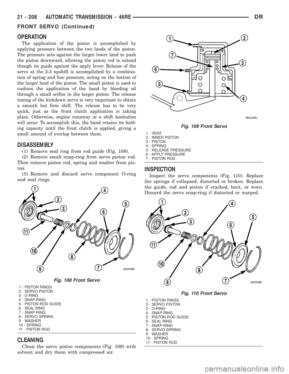
OPERATION
The application of the piston is accomplished by
applying pressure between the two lands of the piston.
The pressure acts against the larger lower land to push
the piston downward, allowing the piston rod to extend
though its guide against the apply lever. Release of the
servo at the 2-3 upshift is accomplished by a combina-
tion of spring and line pressure, acting on the bottom of
the larger land of the piston. The small piston is used to
cushion the application of the band by bleeding oil
through a small orifice in the larger piston. The release
timing of the kickdown servo is very important to obtain
a smooth but firm shift. The release has to be very
quick, just as the front clutch application is taking
place. Otherwise, engine runaway or a shift hesitation
will occur. To accomplish this, the band retains its hold-
ing capacity until the front clutch is applied, giving a
small amount of overlap between them.
DISASSEMBLY
(1) Remove seal ring from rod guide (Fig. 108).
(2) Remove small snap-ring from servo piston rod.
Then remove piston rod, spring and washer from pis-
ton.
(3) Remove and discard servo component O-ring
and seal rings.
CLEANING
Clean the servo piston components (Fig. 109) with
solvent and dry them with compressed air.
INSPECTION
Inspect the servo components (Fig. 110). Replace
the springs if collapsed, distorted or broken. Replace
the guide, rod and piston if cracked, bent, or worn.
Discard the servo snap-ring if distorted or warped.
Fig. 108 Front Servo
1 - PISTON RINGS
2 - SERVO PISTON
3 - O-RING
4 - SNAP-RING
5 - PISTON ROD GUIDE
6 - SEAL RING
7 - SNAP-RING
8 - SERVO SPRING
9 - WASHER
10 - SPRING
11 - PISTON ROD
Fig. 109 Front Servo
1 - VENT
2 - INNER PISTON
3 - PISTON
4 - SPRING
5 - RELEASE PRESSURE
6 - APPLY PRESSURE
7 - PISTON ROD
Fig. 110 Front Servo
1 - PISTON RINGS
2 - SERVO PISTON
3 - O-RING
4 - SNAP-RING
5 - PISTON ROD GUIDE
6 - SEAL RING
7 - SNAP-RING
8 - SERVO SPRING
9 - WASHER
10 - SPRING
11 - PISTON ROD
21 - 208 AUTOMATIC TRANSMISSION - 46REDR
FRONT SERVO (Continued)
Page 2226 of 2895
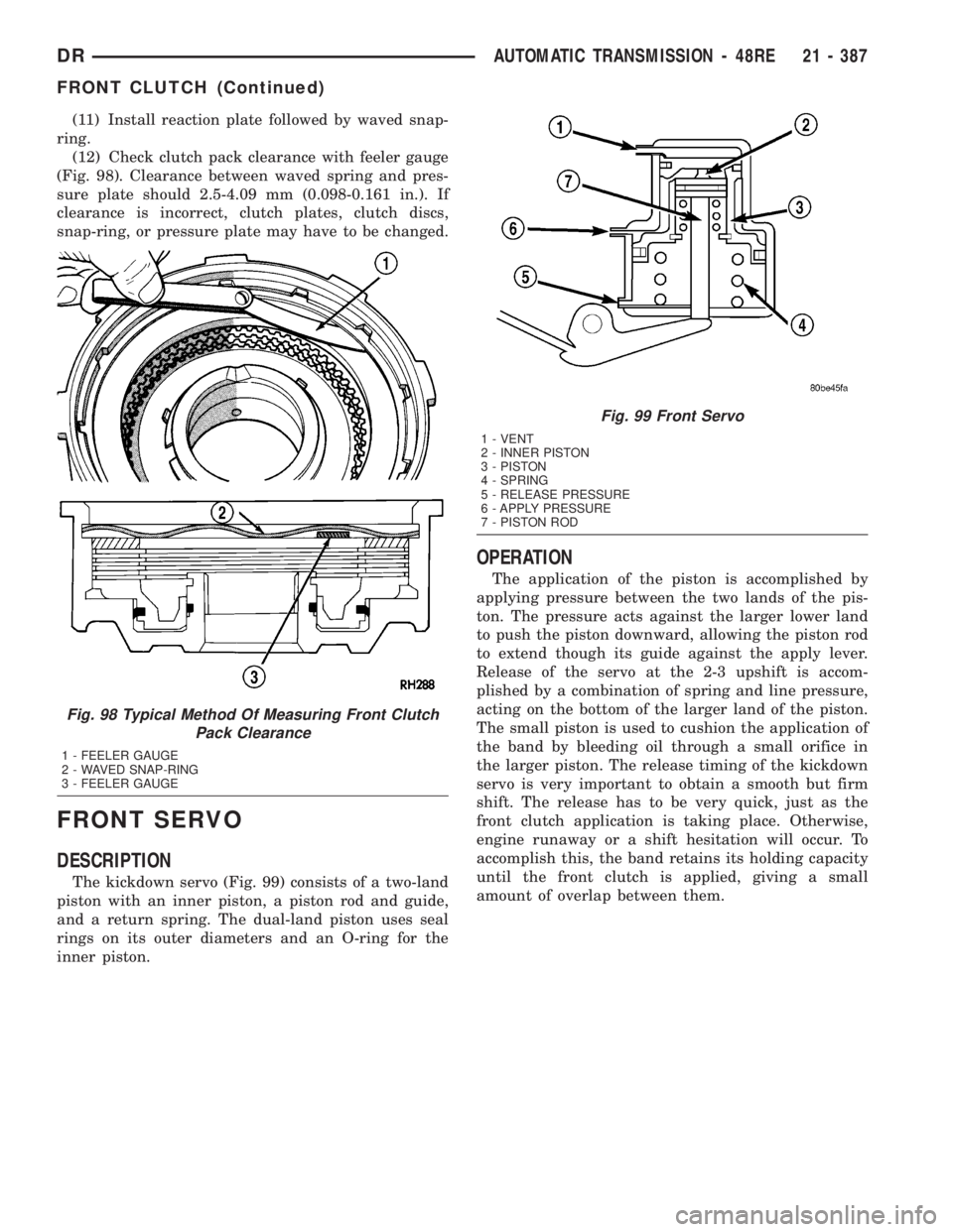
(11) Install reaction plate followed by waved snap-
ring.
(12) Check clutch pack clearance with feeler gauge
(Fig. 98). Clearance between waved spring and pres-
sure plate should 2.5-4.09 mm (0.098-0.161 in.). If
clearance is incorrect, clutch plates, clutch discs,
snap-ring, or pressure plate may have to be changed.
FRONT SERVO
DESCRIPTION
The kickdown servo (Fig. 99) consists of a two-land
piston with an inner piston, a piston rod and guide,
and a return spring. The dual-land piston uses seal
rings on its outer diameters and an O-ring for the
inner piston.
OPERATION
The application of the piston is accomplished by
applying pressure between the two lands of the pis-
ton. The pressure acts against the larger lower land
to push the piston downward, allowing the piston rod
to extend though its guide against the apply lever.
Release of the servo at the 2-3 upshift is accom-
plished by a combination of spring and line pressure,
acting on the bottom of the larger land of the piston.
The small piston is used to cushion the application of
the band by bleeding oil through a small orifice in
the larger piston. The release timing of the kickdown
servo is very important to obtain a smooth but firm
shift. The release has to be very quick, just as the
front clutch application is taking place. Otherwise,
engine runaway or a shift hesitation will occur. To
accomplish this, the band retains its holding capacity
until the front clutch is applied, giving a small
amount of overlap between them.
Fig. 98 Typical Method Of Measuring Front Clutch
Pack Clearance
1 - FEELER GAUGE
2 - WAVED SNAP-RING
3 - FEELER GAUGE
Fig. 99 Front Servo
1 - VENT
2 - INNER PISTON
3 - PISTON
4 - SPRING
5 - RELEASE PRESSURE
6 - APPLY PRESSURE
7 - PISTON ROD
DRAUTOMATIC TRANSMISSION - 48RE 21 - 387
FRONT CLUTCH (Continued)
Page 2777 of 2895
coil. To maintain minimum evaporator temperature
and prevent evaporator freezing, the A/C Fin Probe
which is located in the evaporator cycles the com-
pressor clutch by sending an A/C request to the
JTEC which in turn processes this piece of informa-
tion and if all conditions are met cycles the compres-
sor clutch.
OPERATION - REFRIGERANT SYSTEM SERVICE
PORT
The low pressure service port is located on the suc-
tion refrigerant line, near the accumulator. The high
pressure service port is located on the liquid line at
the passenger side of the engine compartment, near
the condenser.
Each of the service ports has a threaded plastic
protective cap installed over it from the factory. After
servicing the refrigerant system, always reinstall
both of the service port caps.
DIAGNOSIS AND TESTING
DIAGNOSIS AND TESTING - A/C
PERFORMANCE
The air conditioning system is designed to provide
the passenger compartment with low temperature
and low humidity air. The evaporator, located in the
HVAC housing on the dash panel below the instru-
ment panel, is cooled to temperatures near the freez-
ing point. As warm damp air passes through the
cooled evaporator, the air transfers its heat to the
refrigerant in the evaporator and the moisture in the
air condenses on the evaporator fins. During periods
of high heat and humidity, an air conditioning sys-
tem will be more effective in the Recirculation Mode.
With the system in the Recirculation Mode, only air
from the passenger compartment passes through the
evaporator. As the passenger compartment air dehu-
midifies, the air conditioning system performance
levels improve.
Humidity has an important bearing on the temper-
ature of the air delivered to the interior of the vehi-
cle. It is important to understand the effect that
humidity has on the performance of the air condition-
ing system. When humidity is high, the evaporator
has to perform a double duty. It must lower the air
temperature, and it must lower the temperature of
the moisture in the air that condenses on the evapo-
rator fins. Condensing the moisture in the air trans-
fers heat energy into the evaporator fins and tubing.
This reduces the amount of heat the evaporator can
absorb from the air. High humidity greatly reduces
the ability of the evaporator to lower the temperature
of the air.
However, evaporator capacity used to reduce the
amount of moisture in the air is not wasted. Remov-
ing some of the moisture out of the air entering the
vehicle adds to the comfort of the passengers.
Although, an owner may expect too much from the
air conditioning system on humid days. A perfor-
mance test is the best way to determine whether the
system is performing up to standard. This test also
provides valuable clues as to the possible cause of
trouble with the air conditioning system.
Before proceeding, (Refer to 24 - HEATING & AIR
CONDITIONING/PLUMBING - WARNING) and
(Refer to 24 - HEATING & AIR CONDITIONING/
PLUMBING - CAUTION). The air temperature in
the test room and in the vehicle must be a minimum
of 21É C (70É F) for this test.
(1) Connect a tachometer and a manifold gauge set
or A/C recycling/charging station.
(2) Set the A/C Heater mode control switch knob in
the Recirculation Mode position, the temperature
control knob in the full cool position, and the blower
motor switch knob in the highest speed position.
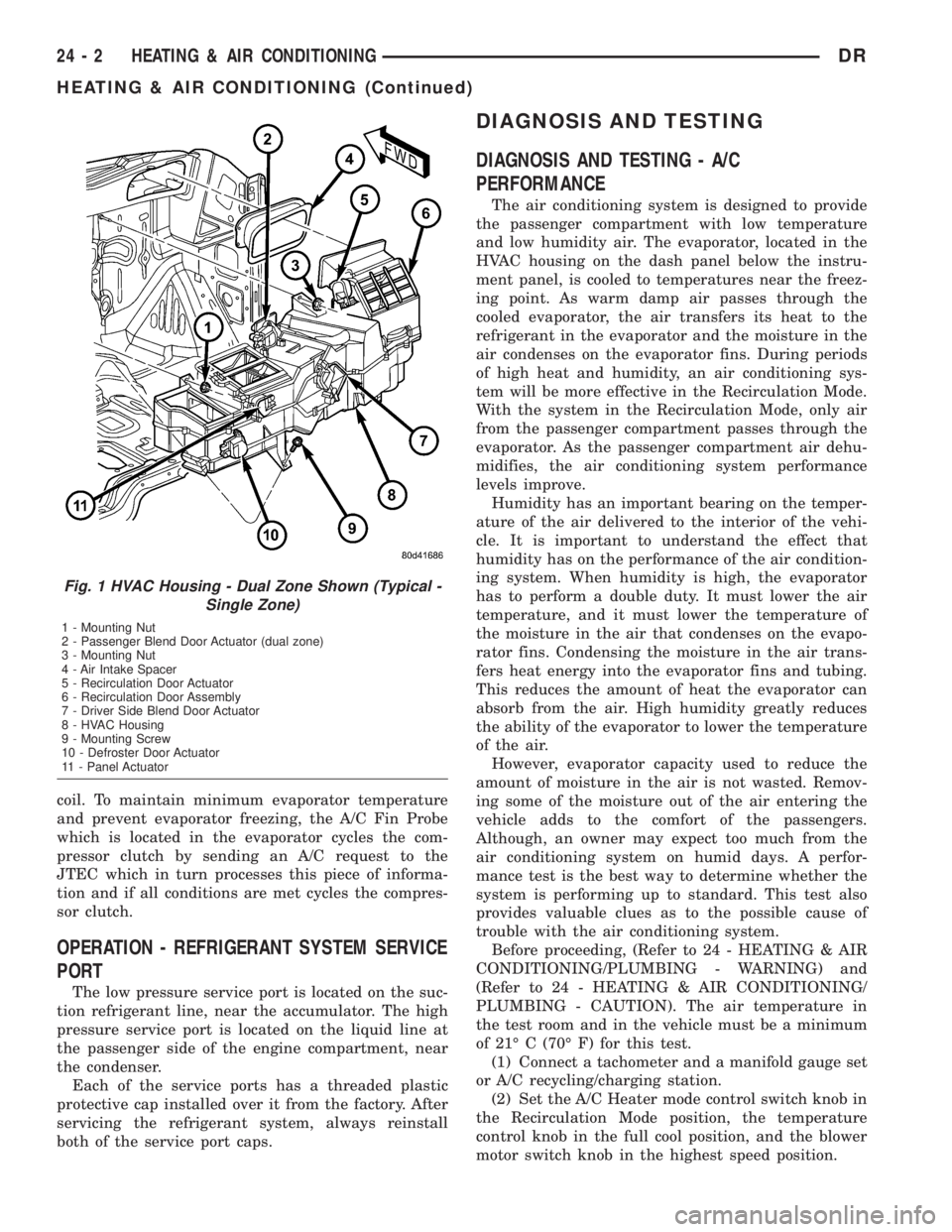
Fig. 1 HVAC Housing - Dual Zone Shown (Typical -
Single Zone)
1 - Mounting Nut
2 - Passenger Blend Door Actuator (dual zone)
3 - Mounting Nut
4 - Air Intake Spacer
5 - Recirculation Door Actuator
6 - Recirculation Door Assembly
7 - Driver Side Blend Door Actuator
8 - HVAC Housing
9 - Mounting Screw
10 - Defroster Door Actuator
11 - Panel Actuator
24 - 2 HEATING & AIR CONDITIONINGDR
HEATING & AIR CONDITIONING (Continued)
Page 2778 of 2895
(3) Start the engine and hold the idle at 1,000 rpm
with the compressor clutch engaged.
(4) The engine should be at operating temperature.
The doors and windows must be closed.
(5) Insert a thermometer in the driver side center
A/C (panel) outlet. Operate the engine for five min-
utes.
(6) The compressor clutch may cycle, depending
upon the ambient temperature and humidity.
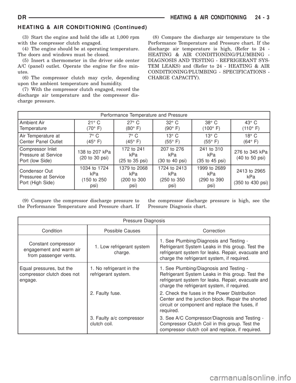
(7) With the compressor clutch engaged, record the
discharge air temperature and the compressor dis-
charge pressure.(8) Compare the discharge air temperature to the
Performance Temperature and Pressure chart. If the
discharge air temperature is high, (Refer to 24 -
HEATING & AIR CONDITIONING/PLUMBING -
DIAGNOSIS AND TESTING - REFRIGERANT SYS-
TEM LEAKS) and (Refer to 24 - HEATING & AIR
CONDITIONING/PLUMBING - SPECIFICATIONS -
CHARGE CAPACITY).
Performance Temperature and Pressure
Ambient Air
Temperature21É C
(70É F)27É C
(80É F)32É C
(90É F)38É C
(100É F)43É C
(110É F)
Air Temperature at
Center Panel Outlet7É C
(45É F)7É C
(45É F)13É C
(55É F)13É C
(55É F)18É C
(64É F)
Compressor Inlet
Pressure at Service
Port (low Side)138 to 207 kPa
(20 to 30 psi)172 to 241
kPa
(25 to 35 psi)207 to 276
kPa
(30 to 40 psi)241 to 310
kPa
(35 to 45 psi)276 to 345 kPa
(40 to 50 psi)
Condensor Out
Pressuree at Service
Port (High Side)1034 to 1724
kPa
(150 to 250
psi)1379 to 2068
kPa
(200 to 300
psi)1724 to 2413
kPa
(250 to 350
psi)1999 to 2689
kPa
(290 to 390
psi)2413 to 2965
kPa
(350 to 430 psi)
(9) Compare the compressor discharge pressure to
the Performance Temperature and Pressure chart. Ifthe compressor discharge pressure is high, see the
Pressure Diagnosis chart.
Pressure Diagnosis
Condition Possible Causes Correction
Constant compressor
engagement and warm air
from passenger vents.1. Low refrigerant system
charge.1. See Plumbing/Diagnosis and Testing -
Refrigerant System Leaks in this group. Test the
refrigerant system for leaks. Repair, evacuate and
charge the refrigerant system, if required.
Equal pressures, but the
compressor clutch does not
engage.1. No refrigerant in the
refrigerant system.1. See Plumbing/Diagnosis and Testing -
Refrigerant System Leaks in this group. Test the
refrigerant system for leaks. Repair, evacuate and
charge the refrigerant system, if required.
2. Faulty fuse. 2. Check the fuses in the Power Distribution
Center and the junction block. Repair the shorted
circuit or component and replace the fuses, if
required.
3. Faulty a/c compressor
clutch coil.3. See A/C Compressor/Diagnosis and Testing -
Compressor Clutch Coil in this group. Test the
compressor clutch coil and replace, if required.
DRHEATING & AIR CONDITIONING 24 - 3
HEATING & AIR CONDITIONING (Continued)
Page 2788 of 2895
NOTE: The air gap is determined by the spacer
shims. When installing an original, or a new clutch
assembly, try the original shims first. When install-
ing a new clutch onto a compressor that previously
did not have a clutch, use a 1.0, 0.50, and 0.13 mil-
limeter (0.040, 0.020, and 0.005 inch) shims from the
new clutch hardware package that is provided with
the new clutch.
(9) To complete the procedure, (Refer to 24 -
HEATING & AIR CONDITIONING/PLUMBING/A/C
COMPRESSOR - INSTALLATION).
A/C COMPRESSOR CLUTCH
RELAY
DESCRIPTION
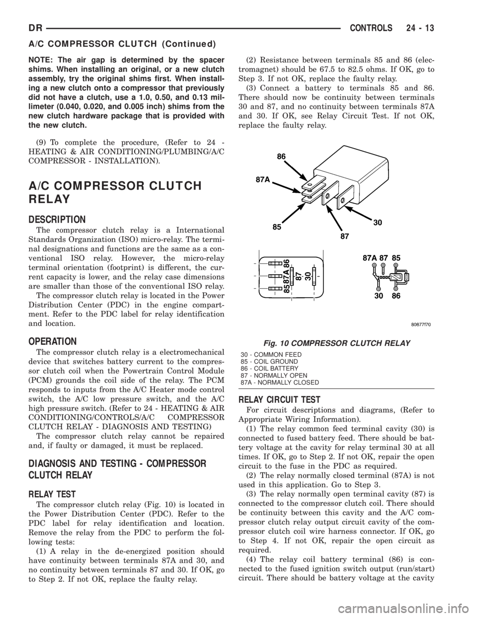
The compressor clutch relay is a International
Standards Organization (ISO) micro-relay. The termi-
nal designations and functions are the same as a con-
ventional ISO relay. However, the micro-relay
terminal orientation (footprint) is different, the cur-
rent capacity is lower, and the relay case dimensions
are smaller than those of the conventional ISO relay.
The compressor clutch relay is located in the Power
Distribution Center (PDC) in the engine compart-
ment. Refer to the PDC label for relay identification
and location.
OPERATION
The compressor clutch relay is a electromechanical
device that switches battery current to the compres-
sor clutch coil when the Powertrain Control Module
(PCM) grounds the coil side of the relay. The PCM
responds to inputs from the A/C Heater mode control
switch, the A/C low pressure switch, and the A/C
high pressure switch. (Refer to 24 - HEATING & AIR
CONDITIONING/CONTROLS/A/C COMPRESSOR
CLUTCH RELAY - DIAGNOSIS AND TESTING)
The compressor clutch relay cannot be repaired
and, if faulty or damaged, it must be replaced.
DIAGNOSIS AND TESTING - COMPRESSOR
CLUTCH RELAY
RELAY TEST
The compressor clutch relay (Fig. 10) is located in
the Power Distribution Center (PDC). Refer to the
PDC label for relay identification and location.
Remove the relay from the PDC to perform the fol-
lowing tests:
(1) A relay in the de-energized position should
have continuity between terminals 87A and 30, and
no continuity between terminals 87 and 30. If OK, go
to Step 2. If not OK, replace the faulty relay.(2) Resistance between terminals 85 and 86 (elec-
tromagnet) should be 67.5 to 82.5 ohms. If OK, go to
Step 3. If not OK, replace the faulty relay.
(3) Connect a battery to terminals 85 and 86.
There should now be continuity between terminals
30 and 87, and no continuity between terminals 87A
and 30. If OK, see Relay Circuit Test. If not OK,
replace the faulty relay.
RELAY CIRCUIT TEST
For circuit descriptions and diagrams, (Refer to
Appropriate Wiring Information).
(1) The relay common feed terminal cavity (30) is
connected to fused battery feed. There should be bat-
tery voltage at the cavity for relay terminal 30 at all
times. If OK, go to Step 2. If not OK, repair the open
circuit to the fuse in the PDC as required.
(2) The relay normally closed terminal (87A) is not
used in this application. Go to Step 3.
(3) The relay normally open terminal cavity (87) is
connected to the compressor clutch coil. There should
be continuity between this cavity and the A/C com-
pressor clutch relay output circuit cavity of the com-
pressor clutch coil wire harness connector. If OK, go
to Step 4. If not OK, repair the open circuit as
required.
(4) The relay coil battery terminal (86) is con-
nected to the fused ignition switch output (run/start)
circuit. There should be battery voltage at the cavity
Fig. 10 COMPRESSOR CLUTCH RELAY
30 - COMMON FEED
85 - COIL GROUND
86 - COIL BATTERY
87 - NORMALLY OPEN
87A - NORMALLY CLOSED
DRCONTROLS 24 - 13
A/C COMPRESSOR CLUTCH (Continued)