2003 DODGE RAM change key battery
[x] Cancel search: change key batteryPage 453 of 2895

diagnostic feedback for the heated seat system. Each
switch also has an incandescent bulb, which provides
dimmer controlled back lighting of the switch when
the headlamps or park lamps are on.
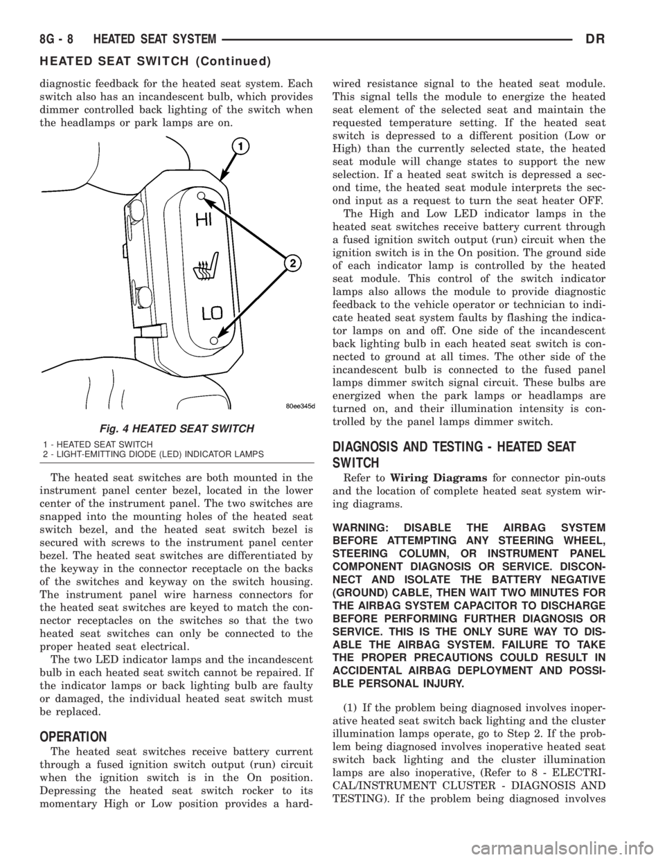
The heated seat switches are both mounted in the
instrument panel center bezel, located in the lower
center of the instrument panel. The two switches are
snapped into the mounting holes of the heated seat
switch bezel, and the heated seat switch bezel is
secured with screws to the instrument panel center
bezel. The heated seat switches are differentiated by
the keyway in the connector receptacle on the backs
of the switches and keyway on the switch housing.
The instrument panel wire harness connectors for
the heated seat switches are keyed to match the con-
nector receptacles on the switches so that the two
heated seat switches can only be connected to the
proper heated seat electrical.
The two LED indicator lamps and the incandescent
bulb in each heated seat switch cannot be repaired. If
the indicator lamps or back lighting bulb are faulty
or damaged, the individual heated seat switch must
be replaced.
OPERATION
The heated seat switches receive battery current
through a fused ignition switch output (run) circuit
when the ignition switch is in the On position.
Depressing the heated seat switch rocker to its
momentary High or Low position provides a hard-wired resistance signal to the heated seat module.
This signal tells the module to energize the heated
seat element of the selected seat and maintain the
requested temperature setting. If the heated seat
switch is depressed to a different position (Low or
High) than the currently selected state, the heated
seat module will change states to support the new
selection. If a heated seat switch is depressed a sec-
ond time, the heated seat module interprets the sec-
ond input as a request to turn the seat heater OFF.
The High and Low LED indicator lamps in the
heated seat switches receive battery current through
a fused ignition switch output (run) circuit when the
ignition switch is in the On position. The ground side
of each indicator lamp is controlled by the heated
seat module. This control of the switch indicator
lamps also allows the module to provide diagnostic
feedback to the vehicle operator or technician to indi-
cate heated seat system faults by flashing the indica-
tor lamps on and off. One side of the incandescent
back lighting bulb in each heated seat switch is con-
nected to ground at all times. The other side of the
incandescent bulb is connected to the fused panel
lamps dimmer switch signal circuit. These bulbs are
energized when the park lamps or headlamps are
turned on, and their illumination intensity is con-
trolled by the panel lamps dimmer switch.
DIAGNOSIS AND TESTING - HEATED SEAT
SWITCH
Refer toWiring Diagramsfor connector pin-outs
and the location of complete heated seat system wir-
ing diagrams.
WARNING: DISABLE THE AIRBAG SYSTEM
BEFORE ATTEMPTING ANY STEERING WHEEL,
STEERING COLUMN, OR INSTRUMENT PANEL
COMPONENT DIAGNOSIS OR SERVICE. DISCON-
NECT AND ISOLATE THE BATTERY NEGATIVE
(GROUND) CABLE, THEN WAIT TWO MINUTES FOR
THE AIRBAG SYSTEM CAPACITOR TO DISCHARGE
BEFORE PERFORMING FURTHER DIAGNOSIS OR
SERVICE. THIS IS THE ONLY SURE WAY TO DIS-
ABLE THE AIRBAG SYSTEM. FAILURE TO TAKE
THE PROPER PRECAUTIONS COULD RESULT IN
ACCIDENTAL AIRBAG DEPLOYMENT AND POSSI-
BLE PERSONAL INJURY.
(1) If the problem being diagnosed involves inoper-
ative heated seat switch back lighting and the cluster
illumination lamps operate, go to Step 2. If the prob-
lem being diagnosed involves inoperative heated seat
switch back lighting and the cluster illumination
lamps are also inoperative, (Refer to 8 - ELECTRI-
CAL/INSTRUMENT CLUSTER - DIAGNOSIS AND
TESTING). If the problem being diagnosed involves
Fig. 4 HEATED SEAT SWITCH
1 - HEATED SEAT SWITCH
2 - LIGHT-EMITTING DIODE (LED) INDICATOR LAMPS
8G - 8 HEATED SEAT SYSTEMDR
HEATED SEAT SWITCH (Continued)
Page 1730 of 2895

INSTALLATION
(1) Install fuel injector(s) into fuel rail assembly
and install retaining clip(s).
(2) If same injector(s) is being reinstalled, install
new o-ring(s).
(3) Apply a small amount of clean engine oil to
each injector o-ring. This will aid in installation.
(4) Install fuel rail. Refer to Fuel Rail Installation.
(5) Start engine and check for fuel leaks.
FUEL PUMP RELAY
DESCRIPTION
The 5±pin, 12±volt, fuel pump relay is located in
the Power Distribution Center (PDC). Refer to the
label on the PDC cover for relay location.
OPERATION
The Powertrain Control Module (PCM) energizes
the electric fuel pump through the fuel pump relay.
The fuel pump relay is energized by first applying
battery voltage to it when the ignition key is turned
ON, and then applying a ground signal to the relay
from the PCM.
Whenever the ignition key is turned ON, the elec-
tric fuel pump will operate. But, the PCM will shut-
down the ground circuit to the fuel pump relay in
approximately 1±3 seconds unless the engine is oper-
ating or the starter motor is engaged.
REMOVAL
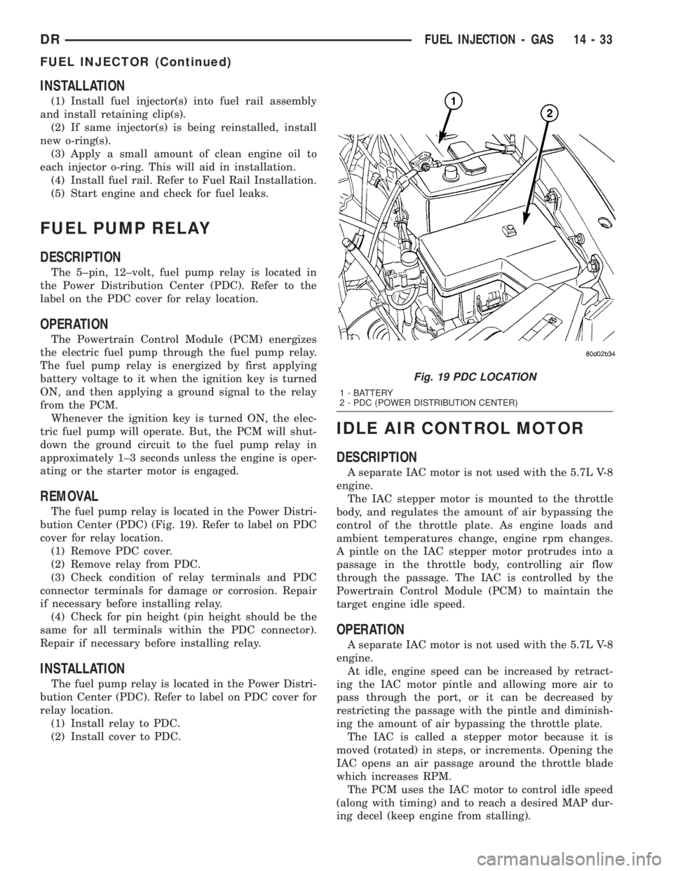
The fuel pump relay is located in the Power Distri-
bution Center (PDC) (Fig. 19). Refer to label on PDC
cover for relay location.
(1) Remove PDC cover.
(2) Remove relay from PDC.
(3) Check condition of relay terminals and PDC
connector terminals for damage or corrosion. Repair
if necessary before installing relay.
(4) Check for pin height (pin height should be the
same for all terminals within the PDC connector).
Repair if necessary before installing relay.
INSTALLATION
The fuel pump relay is located in the Power Distri-
bution Center (PDC). Refer to label on PDC cover for
relay location.
(1) Install relay to PDC.
(2) Install cover to PDC.
IDLE AIR CONTROL MOTOR
DESCRIPTION
A separate IAC motor is not used with the 5.7L V-8
engine.
The IAC stepper motor is mounted to the throttle
body, and regulates the amount of air bypassing the
control of the throttle plate. As engine loads and
ambient temperatures change, engine rpm changes.
A pintle on the IAC stepper motor protrudes into a
passage in the throttle body, controlling air flow
through the passage. The IAC is controlled by the
Powertrain Control Module (PCM) to maintain the
target engine idle speed.
OPERATION
A separate IAC motor is not used with the 5.7L V-8
engine.
At idle, engine speed can be increased by retract-
ing the IAC motor pintle and allowing more air to
pass through the port, or it can be decreased by
restricting the passage with the pintle and diminish-
ing the amount of air bypassing the throttle plate.
The IAC is called a stepper motor because it is
moved (rotated) in steps, or increments. Opening the
IAC opens an air passage around the throttle blade
which increases RPM.
The PCM uses the IAC motor to control idle speed
(along with timing) and to reach a desired MAP dur-
ing decel (keep engine from stalling).
Fig. 19 PDC LOCATION
1 - BATTERY
2 - PDC (POWER DISTRIBUTION CENTER)
DRFUEL INJECTION - GAS 14 - 33
FUEL INJECTOR (Continued)
Page 1779 of 2895

INSTALLATION
Early Diesel Engines
The APPS is serviced (replaced) as one assembly
including the lever, brackets and sensor. The APPS is
calibrated to its mounting bracket.
(1) Snap electrical connector into bottom of sensor.
(2) Position APPS assembly to engine and install 6
bolts. Tighten bolts to 24 N´m (18 ft. lbs.) torque.
(3) Connect wiring harness clip at bottom of
bracket.
(4) If equipped with an automatic transmission,
refer to Group 21, Transmission for transmission con-
trol cable installation procedures.
(5) Install speed control cable into mounting
bracket. Be sure pinch tabs have secured cable.
(6) Install throttle cable into mounting bracket. Be
sure pinch tabs have secured cable.
(7) Connect throttle cable at lever (snaps on).
(8) Connect speed control cable to lever by pushing
cable connector rearward onto lever pin while hold-
ing lever forward.
(9) Install cable cover.
(10) Connect both negative battery cables to both
batteries.
(11)ECM Calibration:Turn key to ON position.
Without starting engine, slowly press throttle pedal
to floor and then slowly release. This step must bedone (one time) to ensure accelerator pedal position
sensor calibration has been learned by ECM. If not
done, possible DTC's may be set.
(12) Use DRB III scan tool to erase any DTC's
from ECM.
Late Diesel Engines
(1) Install Accelerator Pedal Position Sensor
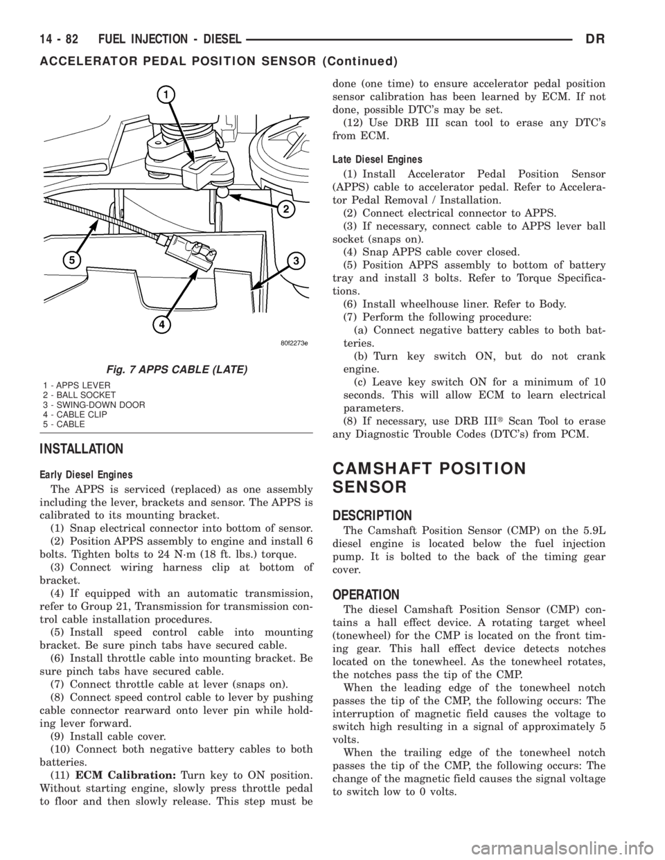
(APPS) cable to accelerator pedal. Refer to Accelera-
tor Pedal Removal / Installation.
(2) Connect electrical connector to APPS.
(3) If necessary, connect cable to APPS lever ball
socket (snaps on).
(4) Snap APPS cable cover closed.
(5) Position APPS assembly to bottom of battery
tray and install 3 bolts. Refer to Torque Specifica-
tions.
(6) Install wheelhouse liner. Refer to Body.
(7) Perform the following procedure:
(a) Connect negative battery cables to both bat-
teries.
(b) Turn key switch ON, but do not crank
engine.
(c) Leave key switch ON for a minimum of 10
seconds. This will allow ECM to learn electrical
parameters.
(8) If necessary, use DRB IIItScan Tool to erase
any Diagnostic Trouble Codes (DTC's) from PCM.CAMSHAFT POSITION
SENSOR
DESCRIPTION
The Camshaft Position Sensor (CMP) on the 5.9L
diesel engine is located below the fuel injection
pump. It is bolted to the back of the timing gear
cover.
OPERATION
The diesel Camshaft Position Sensor (CMP) con-
tains a hall effect device. A rotating target wheel
(tonewheel) for the CMP is located on the front tim-
ing gear. This hall effect device detects notches
located on the tonewheel. As the tonewheel rotates,
the notches pass the tip of the CMP.
When the leading edge of the tonewheel notch
passes the tip of the CMP, the following occurs: The
interruption of magnetic field causes the voltage to
switch high resulting in a signal of approximately 5
volts.
When the trailing edge of the tonewheel notch
passes the tip of the CMP, the following occurs: The
change of the magnetic field causes the signal voltage
to switch low to 0 volts.
Fig. 7 APPS CABLE (LATE)
1 - APPS LEVER
2 - BALL SOCKET
3 - SWING-DOWN DOOR
4 - CABLE CLIP
5 - CABLE
14 - 82 FUEL INJECTION - DIESELDR
ACCELERATOR PEDAL POSITION SENSOR (Continued)