2003 DODGE RAM fan clutch oil
[x] Cancel search: fan clutch oilPage 341 of 2895

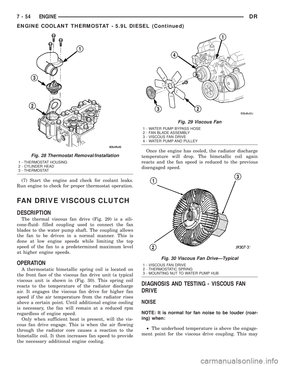
(7) Start the engine and check for coolant leaks.
Run engine to check for proper thermostat operation.
FAN DRIVE VISCOUS CLUTCH
DESCRIPTION
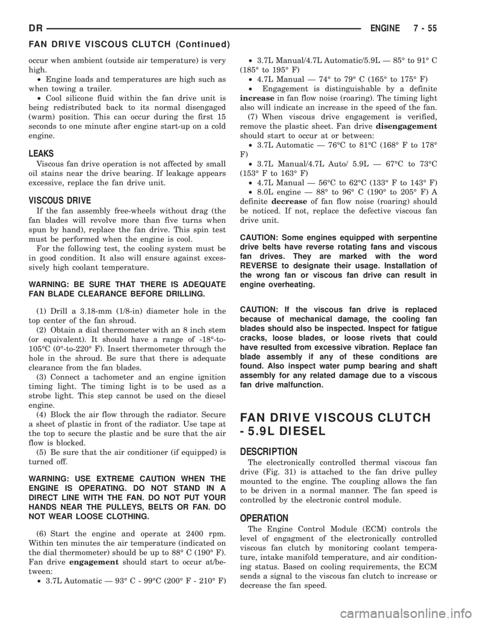
The thermal viscous fan drive (Fig. 29) is a sili-
cone-fluid- filled coupling used to connect the fan
blades to the water pump shaft. The coupling allows
the fan to be driven in a normal manner. This is
done at low engine speeds while limiting the top
speed of the fan to a predetermined maximum level
at higher engine speeds.
OPERATION
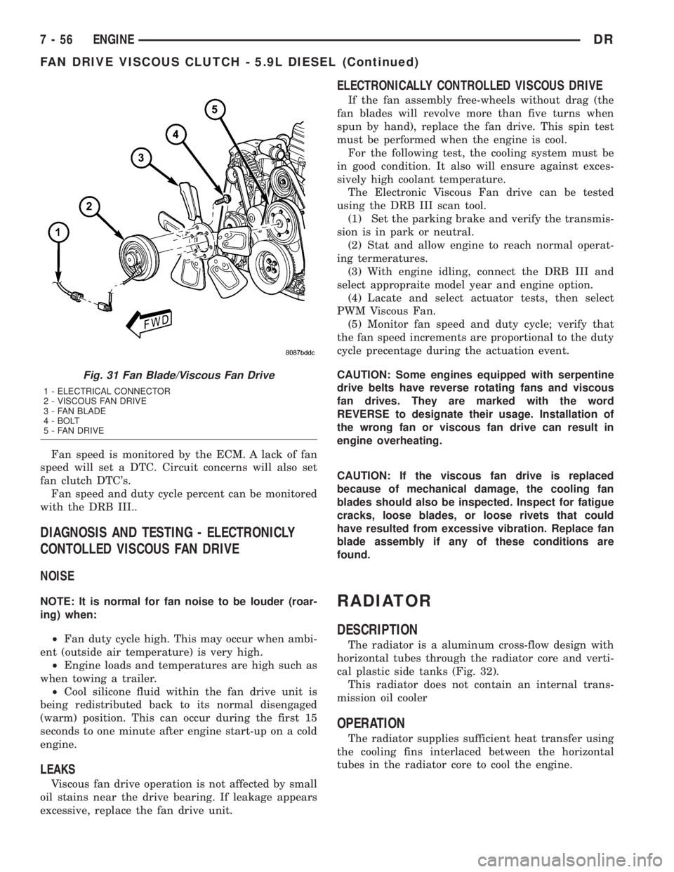
A thermostatic bimetallic spring coil is located on
the front face of the viscous fan drive unit (a typical
viscous unit is shown in (Fig. 30). This spring coil
reacts to the temperature of the radiator discharge
air. It engages the viscous fan drive for higher fan
speed if the air temperature from the radiator rises
above a certain point. Until additional engine cooling
is necessary, the fan will remain at a reduced rpm
regardless of engine speed.
Only when sufficient heat is present, will the vis-
cous fan drive engage. This is when the air flowing
through the radiator core causes a reaction to the
bimetallic coil. It then increases fan speed to provide
the necessary additional engine cooling.Once the engine has cooled, the radiator discharge
temperature will drop. The bimetallic coil again
reacts and the fan speed is reduced to the previous
disengaged speed.
DIAGNOSIS AND TESTING - VISCOUS FAN
DRIVE
NOISE
NOTE: It is normal for fan noise to be louder (roar-
ing) when:
²The underhood temperature is above the engage-
ment point for the viscous drive coupling. This may
Fig. 28 Thermostat Removal/Installation
1 - THERMOSTAT HOUSING
2 - CYLINDER HEAD
3 - THERMOSTAT
Fig. 29 Viscous Fan
1 - WATER PUMP BYPASS HOSE
2 - FAN BLADE ASSEMBLY
3 - VISCOUS FAN DRIVE
4 - WATER PUMP AND PULLEY
Fig. 30 Viscous Fan DriveÐTypical
1 - VISCOUS FAN DRIVE
2 - THERMOSTATIC SPRING
3 - MOUNTING NUT TO WATER PUMP HUB
7 - 54 ENGINEDR
ENGINE COOLANT THERMOSTAT - 5.9L DIESEL (Continued)
Page 342 of 2895

occur when ambient (outside air temperature) is very
high.
²Engine loads and temperatures are high such as
when towing a trailer.
²Cool silicone fluid within the fan drive unit is
being redistributed back to its normal disengaged
(warm) position. This can occur during the first 15
seconds to one minute after engine start-up on a cold
engine.
LEAKS
Viscous fan drive operation is not affected by small
oil stains near the drive bearing. If leakage appears
excessive, replace the fan drive unit.
VISCOUS DRIVE
If the fan assembly free-wheels without drag (the
fan blades will revolve more than five turns when
spun by hand), replace the fan drive. This spin test
must be performed when the engine is cool.
For the following test, the cooling system must be
in good condition. It also will ensure against exces-
sively high coolant temperature.
WARNING: BE SURE THAT THERE IS ADEQUATE
FAN BLADE CLEARANCE BEFORE DRILLING.
(1) Drill a 3.18-mm (1/8-in) diameter hole in the
top center of the fan shroud.
(2) Obtain a dial thermometer with an 8 inch stem
(or equivalent). It should have a range of -18É-to-
105ÉC (0É-to-220É F). Insert thermometer through the
hole in the shroud. Be sure that there is adequate
clearance from the fan blades.
(3) Connect a tachometer and an engine ignition
timing light. The timing light is to be used as a
strobe light. This step cannot be used on the diesel
engine.
(4) Block the air flow through the radiator. Secure
a sheet of plastic in front of the radiator. Use tape at
the top to secure the plastic and be sure that the air
flow is blocked.
(5) Be sure that the air conditioner (if equipped) is
turned off.
WARNING: USE EXTREME CAUTION WHEN THE
ENGINE IS OPERATING. DO NOT STAND IN A
DIRECT LINE WITH THE FAN. DO NOT PUT YOUR
HANDS NEAR THE PULLEYS, BELTS OR FAN. DO
NOT WEAR LOOSE CLOTHING.
(6) Start the engine and operate at 2400 rpm.
Within ten minutes the air temperature (indicated on
the dial thermometer) should be up to 88É C (190É F).
Fan driveengagementshould start to occur at/be-
tween:
²3.7L Automatic Ð 93É C - 99ÉC (200É F - 210É F)²3.7L Manual/4.7L Automatic/5.9L Ð 85É to 91É C
(185É to 195É F)
²4.7L Manual Ð 74É to 79É C (165É to 175É F)
²Engagement is distinguishable by a definite
increasein fan flow noise (roaring). The timing light
also will indicate an increase in the speed of the fan.
(7) When viscous drive engagement is verified,
remove the plastic sheet. Fan drivedisengagement
should start to occur at or between:
²3.7L Automatic Ð 76ÉC to 81ÉC (168É F to 178É
F)
²3.7L Manual/4.7L Auto/ 5.9L Ð 67ÉC to 73ÉC
(153É F to 163É F)
²4.7L Manual Ð 56ÉC to 62ÉC (133É F to 143É F)
²8.0L engine Ð 88É to 96É C (190É to 205É F) A
definitedecreaseof fan flow noise (roaring) should
be noticed. If not, replace the defective viscous fan
drive unit.
CAUTION: Some engines equipped with serpentine
drive belts have reverse rotating fans and viscous
fan drives. They are marked with the word
REVERSE to designate their usage. Installation of
the wrong fan or viscous fan drive can result in
engine overheating.
CAUTION: If the viscous fan drive is replaced
because of mechanical damage, the cooling fan
blades should also be inspected. Inspect for fatigue
cracks, loose blades, or loose rivets that could
have resulted from excessive vibration. Replace fan
blade assembly if any of these conditions are
found. Also inspect water pump bearing and shaft
assembly for any related damage due to a viscous
fan drive malfunction.
FAN DRIVE VISCOUS CLUTCH
- 5.9L DIESEL
DESCRIPTION
The electronically controlled thermal viscous fan
drive (Fig. 31) is attached to the fan drive pulley
mounted to the engine. The coupling allows the fan
to be driven in a normal manner. The fan speed is
controlled by the electronic control module.
OPERATION
The Engine Control Module (ECM) controls the
level of engagment of the electronically controlled
viscous fan clutch by monitoring coolant tempera-
ture, intake manifold temperature, and air condition-
ing status. Based on cooling requirements, the ECM
sends a signal to the viscous fan clutch to increase or
decrease the fan speed.
DRENGINE 7 - 55
FAN DRIVE VISCOUS CLUTCH (Continued)
Page 343 of 2895

Fan speed is monitored by the ECM. A lack of fan
speed will set a DTC. Circuit concerns will also set
fan clutch DTC's.
Fan speed and duty cycle percent can be monitored
with the DRB III..
DIAGNOSIS AND TESTING - ELECTRONICLY
CONTOLLED VISCOUS FAN DRIVE
NOISE
NOTE: It is normal for fan noise to be louder (roar-
ing) when:
²Fan duty cycle high. This may occur when ambi-
ent (outside air temperature) is very high.
²Engine loads and temperatures are high such as
when towing a trailer.
²Cool silicone fluid within the fan drive unit is
being redistributed back to its normal disengaged
(warm) position. This can occur during the first 15
seconds to one minute after engine start-up on a cold
engine.
LEAKS
Viscous fan drive operation is not affected by small
oil stains near the drive bearing. If leakage appears
excessive, replace the fan drive unit.
ELECTRONICALLY CONTROLLED VISCOUS DRIVE
If the fan assembly free-wheels without drag (the
fan blades will revolve more than five turns when
spun by hand), replace the fan drive. This spin test
must be performed when the engine is cool.
For the following test, the cooling system must be
in good condition. It also will ensure against exces-
sively high coolant temperature.
The Electronic Viscous Fan drive can be tested
using the DRB III scan tool.
(1) Set the parking brake and verify the transmis-
sion is in park or neutral.
(2) Stat and allow engine to reach normal operat-
ing termeratures.
(3) With engine idling, connect the DRB III and
select appropraite model year and engine option.
(4) Lacate and select actuator tests, then select
PWM Viscous Fan.
(5) Monitor fan speed and duty cycle; verify that
the fan speed increments are proportional to the duty
cycle precentage during the actuation event.
CAUTION: Some engines equipped with serpentine
drive belts have reverse rotating fans and viscous
fan drives. They are marked with the word
REVERSE to designate their usage. Installation of
the wrong fan or viscous fan drive can result in
engine overheating.
CAUTION: If the viscous fan drive is replaced
because of mechanical damage, the cooling fan
blades should also be inspected. Inspect for fatigue
cracks, loose blades, or loose rivets that could
have resulted from excessive vibration. Replace fan
blade assembly if any of these conditions are
found.
RADIATOR
DESCRIPTION
The radiator is a aluminum cross-flow design with
horizontal tubes through the radiator core and verti-
cal plastic side tanks (Fig. 32).
This radiator does not contain an internal trans-
mission oil cooler
OPERATION
The radiator supplies sufficient heat transfer using
the cooling fins interlaced between the horizontal
tubes in the radiator core to cool the engine.
Fig. 31 Fan Blade/Viscous Fan Drive
1 - ELECTRICAL CONNECTOR
2 - VISCOUS FAN DRIVE
3 - FAN BLADE
4 - BOLT
5 - FAN DRIVE
7 - 56 ENGINEDR
FAN DRIVE VISCOUS CLUTCH - 5.9L DIESEL (Continued)
Page 357 of 2895

CAUTION: A number or letter is stamped into the
tongue of the constant tension clamps. If replace-
ment is necessary, use only an original equipment
clamp with a matching number or letter and width.
(2) Loosen both of the bypass hose clamps and
position them to the center of the hose.
(3) Removethe hose from the vehicle.
INSTALLATION
INSTALLATION - WATER PUMP BYPASS HOSE
WITH AIR CONDITIONING
(1) Position the bypass hose clamps to the center
of the bypass hose.
(2) Install the bypass hose to the engine.
(3) Secure both of the hose clamps.
(4) Install the generator-A/C mounting bracket
assembly to the engine. Tighten bolt number 1 (Fig.
53) to 41 N´m (30 ft. lbs.). Tighten bolt number 2
(Fig. 53) to 28 N´m (20 ft. lbs.). Tighten bracket
mounting bolts (Fig. 53) (Fig. 53) to 40 N´m (30 ft.
lbs.).
(5) Install a new O-ring to the heater hose coolant
return tube. Coat the new O-ring with antifreeze
before installation.
(6) Install the coolant return tube and its mount-
ing bolt to the engine.
(7) Connect the throttle body control cables.
(8) Install the oil dipstick mounting bolt.
(9) Install the idler pulley. Tighten the bolt to 41
N´m (30 ft. lbs.) (Fig. 57).
(10) Install the drive belt (Refer to 7 - COOLING/
ACCESSORY DRIVE/DRIVE BELTS - INSTALLA-
TION).CAUTION: When installing the serpentine accessory
drive belt, the belt must be routed correctly. If not,
the engine may overheat due to the water pump
rotating in the wrong direction (Refer to 7 - COOL-
ING/ACCESSORY DRIVE/DRIVE BELTS - INSTALLA-
TION). The correct belt with the correct length must
be used.
(11) Install the air cleaner assembly.
(12) Install the upper radiator hose to the radiator.
(13) Connect the throttle cable to the clip at the
radiator fan shroud.
(14) Connect the wiring harness to the A/C com-
pressor.
(15) Fill the cooling system (Refer to 7 - COOLING
- STANDARD PROCEDURE).
(16) Start and warm the engine. Check for leaks.
INSTALLATION - WATER PUMP BYPASS HOSE
WITHOUT AIR CONDITIONING
(1) Position the bypass hose clamps to the center
of the bypass hose.
(2) Install the bypass hose tothe engine.
(3) Secure both of the hose clamps.
(4) Fill the cooling system (Refer to 7 - COOLING
- STANDARD PROCEDURE).
(5) Start and warm the engine. Check for leaks.
WATER PUMP - 5.7L
REMOVAL
(1) Disconnect negative battery cable.
(2) Drain coolant.
(3) Remove serpentine belt.
(4) Remove fan clutch assembly.
(5) Remove coolant fill bottle.
Fig. 56 Water Pump Bypass Hose - Typical
1 - WATER PUMP BYPASS HOSE
2 - FAN BLADE ASSEMBLY
3 - VISCOUS FAN DRIVE
4 - WATER PUMP AND PULLEY
Fig. 57 Tensioner Mounting
1 - DOWEL PIN HOLE
2 - TENSIONER MOUNTING BRACKET
7 - 70 ENGINEDR
WATER PUMP INLET TUBE - 5.9L (Continued)
Page 385 of 2895

ENGINE CONTROL MODULE
DESCRIPTION - ECM
The Engine Control Module (ECM) is bolted to the
left side of the engine below the intake manifold (Fig.
2).
OPERATION - ECM
The main function of the Engine Control Module
(ECM) is to electrically control the fuel system. The
Powertrain Control Module (PCM)does not control
the fuel system.
The ECM can adapt its programming to meet
changing operating conditions.If the ECM has
been replaced, flashed or re-calibrated, the
ECM must learn the Accelerator Pedal Position
Sensor (APPS) idle voltage. Failure to learn
this voltage may result in unnecessary diagnos-
tic trouble codes. Refer to ECM Removal/Instal-
lation for learning procedures.
The ECM receives input signals from various
switches and sensors. Based on these inputs, the
ECM regulates various engine and vehicle operations
through different system components. These compo-
nents are referred to asECM Outputs.The sensors
and switches that provide inputs to the ECM are
consideredECM Inputs.NOTE: ECM Inputs:
²Accelerator Pedal Position Sensor (APPS) Volts
²APPS1 Signal Ð For off engine APPS
²APPS2 Signal Ð For off engine APPS
²APPS Idle Validation Switches #1 and #2
²Battery voltage
²Camshaft Position Sensor (CMP)
²CCD bus (+) circuits
²CCD bus (-) circuits
²Crankshaft Position Sensor (CKP)
²Data link connection for DRB scan tool
²Engine Coolant Temperature (ECT) sensor
²Ground circuits
²Fuel Pressure Sensor
²Battery Temperature
²Fan speed
²Inlet Air Temperature Sensor/Pressure Sensor
²Intake Air Temperature Sensor/MAP Sensor
²Oil Pressure SWITCH
²Power ground
²Sensor return
²Signal ground
²Water-In-Fuel (WIF) sensor
NOTE: ECM Outputs:
After inputs are received by the ECM, certain sen-
sors, switches and components are controlled or reg-
ulated by the ECM. These are consideredECM
Outputs.These outputs are for:
²CCD bus (+) circuits
²CCD bus (-) circuits
²CKP and APPS outputs to the PCM
²Data link connection for DRB scan tool
²Five volt sensor supply
²Fuel transfer (lift) pump
²Intake manifold air heater relays #1 and #2 con-
trol circuits
²Malfunction indicator lamp (Check engine lamp)
(databus)
²Oil Pressure Swith/warning lamp (databus)
²Fuel Control Actuator
²Wait-to-start warning lamp (databus)
²Fan Clutch PWM
²Water-In-Fuel (WIF) warning lamp (databus)
REMOVAL
The Engine Control Module (ECM) is bolted to a
support bracket near the fuel filter. The support
bracket mounts to the block with four capscrews and
vibration isolators. A ground wire is fastened to the
bracket. The other end of the wire is fastened to the
engine block.
(1) Record any Diagnostic Trouble Codes (DTC's)
found in the ECM.
Fig. 2 DIESEL ECM
1 - ENGINE CONTROL MODULE (ECM)
2 - ECM MOUNTING BOLT
3 - 50-WAY CONNECTOR
4 - SUPPORT PLATE
5 - 60-WAY CONNECTOR
8E - 4 ELECTRONIC CONTROL MODULESDR
Page 392 of 2895

OPERATION
OPERATION - PCM
The PCM operates the fuel system. The PCM is a
pre-programmed, triple microprocessor digital com-
puter. It regulates ignition timing, air-fuel ratio,
emission control devices, charging system, certain
transmission features, speed control, air conditioning
compressor clutch engagement and idle speed. The
PCM can adapt its programming to meet changing
operating conditions.
The PCM receives input signals from various
switches and sensors. Based on these inputs, the
PCM regulates various engine and vehicle operations
through different system components. These compo-
nents are referred to as Powertrain Control Module
(PCM) Outputs. The sensors and switches that pro-
vide inputs to the PCM are considered Powertrain
Control Module (PCM) Inputs.
The PCM adjusts ignition timing based upon
inputs it receives from sensors that react to: engine
rpm, manifold absolute pressure, engine coolant tem-
perature, throttle position, transmission gear selec-
tion (automatic transmission), vehicle speed, power
steering pump pressure, and the brake switch.
The PCM adjusts idle speed based on inputs it
receives from sensors that react to: throttle position,
vehicle speed, transmission gear selection, engine
coolant temperature and from inputs it receives from
the air conditioning clutch switch and brake switch.
Based on inputs that it receives, the PCM adjusts
ignition coil dwell. The PCM also adjusts the gener-
ator charge rate through control of the generator
field and provides speed control operation.
NOTE: PCM Inputs:
²ABS module (if equipped)
²A/C request (if equipped with factory A/C)
²A/C select (if equipped with factory A/C)
²A/C pressure transducer
²Auto shutdown (ASD) sense
²Battery temperature sensor
²Battery voltage
²Brake switch
²J1850 bus (+) circuits
²J1850 bus (-) circuits
²Camshaft position sensor signal
²Crankshaft position sensor
²Data link connection for DRB scan tool
²EATX module (if equipped)
²Engine coolant temperature sensor
²Fuel level (through J1850 circuitry)
²Generator (battery voltage) output
²Ignition circuit sense (ignition switch in on/off/
crank/run position)²Intake manifold air temperature sensor
²Knock sensors (2 on 3.7L engine)
²Leak detection pump (switch) sense (if equipped)
²Manifold absolute pressure (MAP) sensor
²Oil pressure
²Oxygen sensors
²Park/neutral switch (auto. trans. only)
²Power ground
²Power steering pressure switch (if equipped)
²Sensor return
²Signal ground
²Speed control multiplexed single wire input
²Throttle position sensor
²Transfer case switch (4WD range position)
²Vehicle speed signal
NOTE: PCM Outputs:
²A/C clutch relay
²Auto shutdown (ASD) relay
²J1850 bus (+/-) circuits for: speedometer, voltme-
ter, fuel gauge, oil pressure gauge/lamp, engine temp.
gauge and speed control warn. lamp
²Data link connection for DRB scan tool
²EGR valve control solenoid (if equipped)
²EVAP canister purge solenoid
²Five volt sensor supply (primary)
²Five volt sensor supply (secondary)
²Fuel injectors
²Fuel pump relay
²Generator field driver (-)
²Generator field driver (+)
²Idle air control (IAC) motor
²Ignition coil(s)
²Leak detection pump (if equipped)
²Malfunction indicator lamp (Check engine lamp).
Driven through J1850 circuits.
²Oxygen sensor heater relays
²Oxygen sensors (pulse width modulated)
²Radiator cooling fan relay (pulse width modu-
lated)
²Speed control vacuum solenoid
²Speed control vent solenoid
²Tachometer (if equipped). Driven through J1850
circuits.
²Transmission convertor clutch circuit. Driven
through J1850 circuits.
OPERATION - 5 VOLT SUPPLIES
Primary 5±volt supply:
²supplies the required 5 volt power source to the
Crankshaft Position (CKP) sensor.
²supplies the required 5 volt power source to the
Camshaft Position (CMP) sensor.
²supplies a reference voltage for the Manifold
Absolute Pressure (MAP) sensor.
DRELECTRONIC CONTROL MODULES 8E - 11
POWERTRAIN CONTROL MODULE (Continued)
Page 701 of 2895

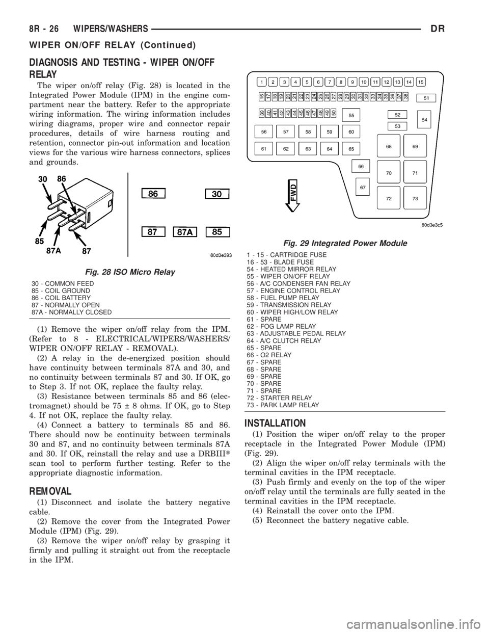
DIAGNOSIS AND TESTING - WIPER ON/OFF
RELAY
The wiper on/off relay (Fig. 28) is located in the
Integrated Power Module (IPM) in the engine com-
partment near the battery. Refer to the appropriate
wiring information. The wiring information includes
wiring diagrams, proper wire and connector repair
procedures, details of wire harness routing and
retention, connector pin-out information and location
views for the various wire harness connectors, splices
and grounds.
(1) Remove the wiper on/off relay from the IPM.
(Refer to 8 - ELECTRICAL/WIPERS/WASHERS/
WIPER ON/OFF RELAY - REMOVAL).
(2) A relay in the de-energized position should
have continuity between terminals 87A and 30, and
no continuity between terminals 87 and 30. If OK, go
to Step 3. If not OK, replace the faulty relay.
(3) Resistance between terminals 85 and 86 (elec-
tromagnet) should be 75 8 ohms. If OK, go to Step
4. If not OK, replace the faulty relay.
(4) Connect a battery to terminals 85 and 86.
There should now be continuity between terminals
30 and 87, and no continuity between terminals 87A
and 30. If OK, reinstall the relay and use a DRBIIIt
scan tool to perform further testing. Refer to the
appropriate diagnostic information.
REMOVAL
(1) Disconnect and isolate the battery negative
cable.
(2) Remove the cover from the Integrated Power
Module (IPM) (Fig. 29).
(3) Remove the wiper on/off relay by grasping it
firmly and pulling it straight out from the receptacle
in the IPM.
INSTALLATION
(1) Position the wiper on/off relay to the proper
receptacle in the Integrated Power Module (IPM)
(Fig. 29).
(2) Align the wiper on/off relay terminals with the
terminal cavities in the IPM receptacle.
(3) Push firmly and evenly on the top of the wiper
on/off relay until the terminals are fully seated in the
terminal cavities in the IPM receptacle.
(4) Reinstall the cover onto the IPM.
(5) Reconnect the battery negative cable.
Fig. 28 ISO Micro Relay
30 - COMMON FEED
85 - COIL GROUND
86 - COIL BATTERY
87 - NORMALLY OPEN
87A - NORMALLY CLOSED
Fig. 29 Integrated Power Module
1 - 15 - CARTRIDGE FUSE
16 - 53 - BLADE FUSE
54 - HEATED MIRROR RELAY
55 - WIPER ON/OFF RELAY
56 - A/C CONDENSER FAN RELAY
57 - ENGINE CONTROL RELAY
58 - FUEL PUMP RELAY
59 - TRANSMISSION RELAY
60 - WIPER HIGH/LOW RELAY
61 - SPARE
62 - FOG LAMP RELAY
63 - ADJUSTABLE PEDAL RELAY
64 - A/C CLUTCH RELAY
65 - SPARE
66 - O2 RELAY
67 - SPARE
68 - SPARE
69 - SPARE
70 - SPARE
71 - SPARE
72 - STARTER RELAY
73 - PARK LAMP RELAY
8R - 26 WIPERS/WASHERSDR
WIPER ON/OFF RELAY (Continued)
Page 720 of 2895

8W-02 COMPONENT INDEX
Component Page
4WD Switch......................... 8W-30
A/C Compressor Clutch Relay............ 8W-42
A/C Compressor Clutch................. 8W-42
A/C Pressure Transducer................ 8W-42
A/C-Heater Control.................... 8W-42
Accelerator Pedal Position Sensor......... 8W-30
Adjustable Pedal Motor................. 8W-30
Adjustable Pedal Relay................. 8W-30
Adjustable Pedal Switch................ 8W-30
Airbag Control Modules................ 8W-43
Airbags............................. 8W-43
Ambient Temperature Sensor............ 8W-49
Amplifier Audio....................... 8W-47
Auto Shut Down Relay................. 8W-30
Automatic Day/Night Mirror............. 8W-49
Auxiliary Battery..................... 8W-20
Backup Lamp Switch.................. 8W-51
Battery Temperature Sensor............. 8W-30
Battery............................. 8W-20
Blend Door Actuator................... 8W-42
Blower Motor Resistor Block............. 8W-42
Blower Motor......................... 8W-42
Brake Lamp Switch.................... 8W-33
Brake Transmission Shift Interlock
Solenoid........................... 8W-40
Camshaft Position Sensor............... 8W-30
Capacitor............................ 8W-30
Center High Mounted Stop Lamp/Cargo
Lamp.......................... 8W-44, 51
Center High Mounted Stop Lamp-
Aftermarket..................... 8W-33, 51
Cigar Lighter Outlet................... 8W-41
Circuit Breaker....................... 8W-10
Clearance Lamps...................... 8W-50
Clockspring................. 8W-33, 41, 43, 47
Clutch Interlock Brake Switch........... 8W-21
Coil On Plugs........................ 8W-30
Compass/Mini-Trip Computer............ 8W-49
Condenser Fan Relay.................. 8W-42
Condenser Fan....................... 8W-42
Controller Antilock Brake............ 8W-34, 35
Crankshaft Position Sensor.............. 8W-30
Cylinder Lock Switch-Driver............. 8W-61
Cylinder Lock Switch-Passenger.......... 8W-61
Data Link Connector................... 8W-18
Data Link Connector-Engine............. 8W-18
Dome Lamp.......................... 8W-44
Door Ajar Switches.................... 8W-40
Door Lock Motor/Ajar Switches........ 8W-40, 61
Door Lock Switch-Passenger............. 8W-61
Driver Door Module.............. 8W-60, 61, 62
Electric Brake Provision............. 8W-33, 54Component Page
Electronic Throttle Control Module........ 8W-30
Engine Control Module................. 8W-30
Engine Coolant Temperature Sensor....... 8W-30
Engine Oil Pressure Switch.............. 8W-30
EVAP/Purge Solenoid.................. 8W-30
Evaporator Temperature Sensor.......... 8W-42
Fender Lamps........................ 8W-51
Fog Lamp Relay...................... 8W-50
Fog Lamps.......................... 8W-50
Front Control Module.................. 8W-10
Fuel Heater Relay..................... 8W-30
Fuel Heater.......................... 8W-30
Fuel Injectors........................ 8W-30
Fuel Injector Packs.................... 8W-30
Fuel Pump Module.................... 8W-30
Fuel Pump Motor..................... 8W-30
Fuel Pump Relay...................... 8W-30
Fuel Rail Pressure Sensor............... 8W-30
Fuses............................... 8W-10
Fusible Link......................... 8W-10
Grounds............................ 8W-15
Generator........................... 8W-20
Glove Box Lamp And Switch............. 8W-44
Headlamp Switch.................. 8W-40, 50
Headlamps.......................... 8W-50
Heated Mirror Relay................... 8W-62
Heated Seat Cushions.................. 8W-63
Heated Seat Switches.................. 8W-63
Horn Relay.......................... 8W-41
Horn Switch......................... 8W-41
Horns.............................. 8W-41
Idle Air Control Motor............ 8W-30, 30-36
Ignition Coils......................... 8W-30
Ignition Switch....................... 8W-10
Inlet Air Temperature/Pressure Sensor..... 8W-30
Input Speed Sensor.................... 8W-31
Instrument Cluster.................... 8W-40
Intake Air Heater Relays............... 8W-30
Intake Air Temperature Sensor........... 8W-30
Intake Air Temperature/Manifold Absolute
Pressure Sensor..................... 8W-30
Integrated Power Module............... 8W-10
Knock Sensors........................ 8W-30
Leak Detection Pump.................. 8W-30
License Lamps....................... 8W-51
Lift Pump Motor...................... 8W-30
Line Pressure Sensor................ 8W-30, 31
Lumbar Motors....................... 8W-63
Manifold Absolute Pressure Sensor........ 8W-30
Mode Door Actuators................... 8W-42
Multi-Function Switch............ 8W-40, 52, 53
Output Speed Sensor................... 8W-31
DR8W-02 COMPONENT INDEX 8W - 02 - 1