2003 DODGE RAM engine oil capacity
[x] Cancel search: engine oil capacityPage 2811 of 2895

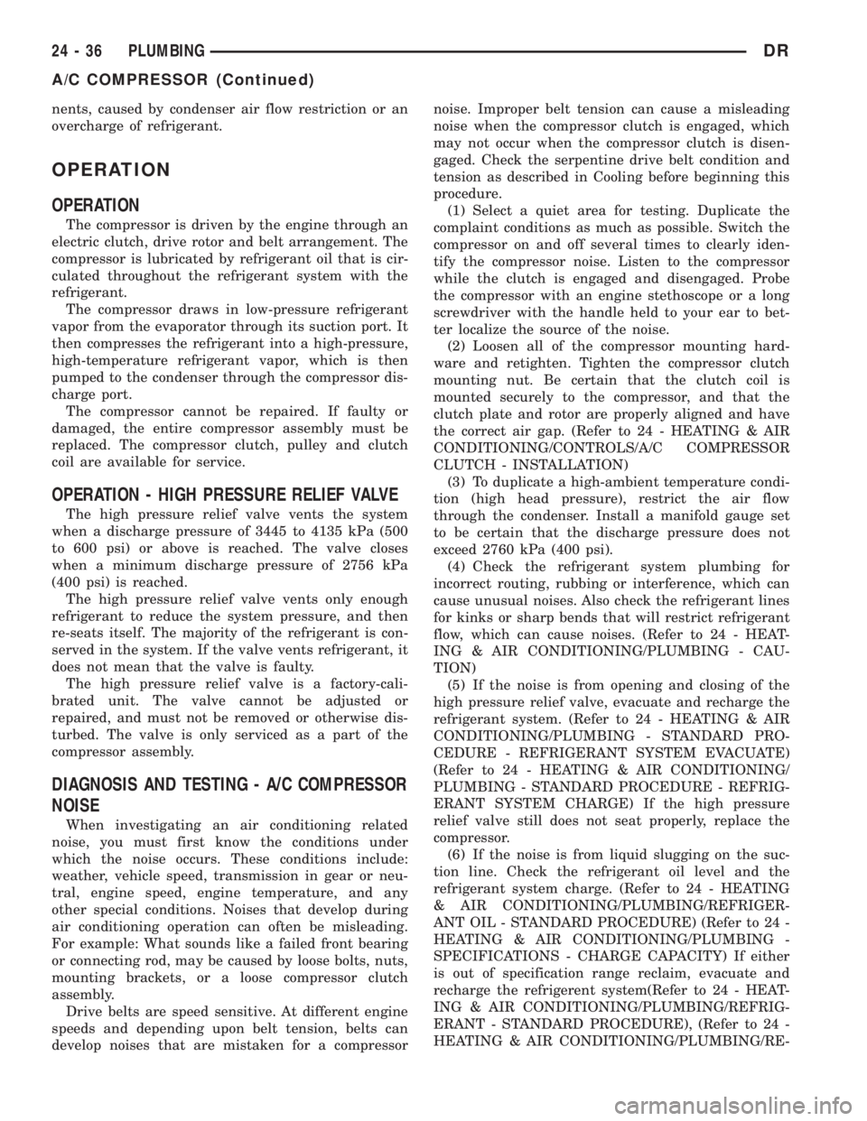
nents, caused by condenser air flow restriction or an
overcharge of refrigerant.
OPERATION
OPERATION
The compressor is driven by the engine through an
electric clutch, drive rotor and belt arrangement. The
compressor is lubricated by refrigerant oil that is cir-
culated throughout the refrigerant system with the
refrigerant.
The compressor draws in low-pressure refrigerant
vapor from the evaporator through its suction port. It
then compresses the refrigerant into a high-pressure,
high-temperature refrigerant vapor, which is then
pumped to the condenser through the compressor dis-
charge port.
The compressor cannot be repaired. If faulty or
damaged, the entire compressor assembly must be
replaced. The compressor clutch, pulley and clutch
coil are available for service.
OPERATION - HIGH PRESSURE RELIEF VALVE
The high pressure relief valve vents the system
when a discharge pressure of 3445 to 4135 kPa (500
to 600 psi) or above is reached. The valve closes
when a minimum discharge pressure of 2756 kPa
(400 psi) is reached.
The high pressure relief valve vents only enough
refrigerant to reduce the system pressure, and then
re-seats itself. The majority of the refrigerant is con-
served in the system. If the valve vents refrigerant, it
does not mean that the valve is faulty.
The high pressure relief valve is a factory-cali-
brated unit. The valve cannot be adjusted or
repaired, and must not be removed or otherwise dis-
turbed. The valve is only serviced as a part of the
compressor assembly.
DIAGNOSIS AND TESTING - A/C COMPRESSOR
NOISE
When investigating an air conditioning related
noise, you must first know the conditions under
which the noise occurs. These conditions include:
weather, vehicle speed, transmission in gear or neu-
tral, engine speed, engine temperature, and any
other special conditions. Noises that develop during
air conditioning operation can often be misleading.
For example: What sounds like a failed front bearing
or connecting rod, may be caused by loose bolts, nuts,
mounting brackets, or a loose compressor clutch
assembly.
Drive belts are speed sensitive. At different engine
speeds and depending upon belt tension, belts can
develop noises that are mistaken for a compressornoise. Improper belt tension can cause a misleading
noise when the compressor clutch is engaged, which
may not occur when the compressor clutch is disen-
gaged. Check the serpentine drive belt condition and
tension as described in Cooling before beginning this
procedure.
(1) Select a quiet area for testing. Duplicate the
complaint conditions as much as possible. Switch the
compressor on and off several times to clearly iden-
tify the compressor noise. Listen to the compressor
while the clutch is engaged and disengaged. Probe
the compressor with an engine stethoscope or a long
screwdriver with the handle held to your ear to bet-
ter localize the source of the noise.
(2) Loosen all of the compressor mounting hard-
ware and retighten. Tighten the compressor clutch
mounting nut. Be certain that the clutch coil is
mounted securely to the compressor, and that the
clutch plate and rotor are properly aligned and have
the correct air gap. (Refer to 24 - HEATING & AIR
CONDITIONING/CONTROLS/A/C COMPRESSOR
CLUTCH - INSTALLATION)
(3) To duplicate a high-ambient temperature condi-
tion (high head pressure), restrict the air flow
through the condenser. Install a manifold gauge set
to be certain that the discharge pressure does not
exceed 2760 kPa (400 psi).
(4) Check the refrigerant system plumbing for
incorrect routing, rubbing or interference, which can
cause unusual noises. Also check the refrigerant lines
for kinks or sharp bends that will restrict refrigerant
flow, which can cause noises. (Refer to 24 - HEAT-
ING & AIR CONDITIONING/PLUMBING - CAU-
TION)
(5) If the noise is from opening and closing of the
high pressure relief valve, evacuate and recharge the
refrigerant system. (Refer to 24 - HEATING & AIR
CONDITIONING/PLUMBING - STANDARD PRO-
CEDURE - REFRIGERANT SYSTEM EVACUATE)
(Refer to 24 - HEATING & AIR CONDITIONING/
PLUMBING - STANDARD PROCEDURE - REFRIG-
ERANT SYSTEM CHARGE) If the high pressure
relief valve still does not seat properly, replace the
compressor.
(6) If the noise is from liquid slugging on the suc-
tion line. Check the refrigerant oil level and the
refrigerant system charge. (Refer to 24 - HEATING
& AIR CONDITIONING/PLUMBING/REFRIGER-
ANT OIL - STANDARD PROCEDURE) (Refer to 24 -
HEATING & AIR CONDITIONING/PLUMBING -
SPECIFICATIONS - CHARGE CAPACITY) If either
is out of specification range reclaim, evacuate and
recharge the refrigerent system(Refer to 24 - HEAT-
ING & AIR CONDITIONING/PLUMBING/REFRIG-
ERANT - STANDARD PROCEDURE), (Refer to 24 -
HEATING & AIR CONDITIONING/PLUMBING/RE-
24 - 36 PLUMBINGDR
A/C COMPRESSOR (Continued)
Page 2827 of 2895

air and boil the moisture out of the system at near
room temperature. To evacuate the refrigerant sys-
tem, use the following procedure:
(1) Connect a R-134a refrigerant recovery/recy-
cling/charging station that meets SAE Standard
J2210 and a manifold gauge set (if required) to the
refrigerant system of the vehicle and recover refrig-
erant.
(2) Open the low and high side valves and start
the charging station vacuum pump. When the suc-
tion gauge reads 88 kPa (26 in. Hg.) vacuum or
greater, close all of the valves and turn off the vac-
uum pump.
(a) If the refrigerant system fails to reach the
specified vacuum, the system has a leak that must
be corrected. See Refrigerant System Leaks in the
Diagnosis and Testing section of this group for the
procedures.
(b) If the refrigerant system maintains the spec-
ified vacuum for five minutes, restart the vacuum
pump, open the suction and discharge valves and
evacuate the system for an additional ten minutes.
(3) Close all of the valves, and turn off the charg-
ing station vacuum pump.
(4) The refrigerant system is now ready to be
charged with R-134a refrigerant(Refer to 24 - HEAT-
ING & AIR CONDITIONING/PLUMBING/REFRIG-
ERANT - STANDARD PROCEDURE).
STANDARD PROCEDURE- REFRIGERANT
RECOVERY
WARNING: (Refer to 24 - HEATING & AIR CONDI-
TIONING/PLUMBING - WARNING) AND (Refer to 24 -
HEATING & AIR CONDITIONING/PLUMBING - CAU-
TION) BEFORE PERFORMING THE FOLLOWING
OPERATION.
A R-134a refrigerant recovery/recycling/charging
station that meets SAE Standard J2210 must be
used to recover the refrigerant from an R-134a refrig-
erant system. Refer to the operating instructions sup-
plied by the equipment manufacturer for the proper
care and use of this equipment.
STANDARD PROCEDURE- REFRIGERANT
SYSTEM CHARGE
WARNING: (Refer to 24 - HEATING & AIR CONDI-
TIONING/PLUMBING - WARNING) AND (Refer to 24 -
HEATING & AIR CONDITIONING/PLUMBING - CAU-
TION) BEFORE PERFORMING THE FOLLOWING
OPERATION.
After the refrigerant system has been tested for
leaks and evacuated, a refrigerant charge can beinjected into the system. See Refrigerant Charge
Capacity in the Service Procedures section of this
group for the proper amount of the refrigerant
charge, this fill level can also be found on a label
attached under the hood of the vehicle..
A R-134a refrigerant recovery/recycling/charging
station that meets SAE Standard J2210 must be
used to charge the refrigerant system with R-134a
refrigerant. Refer to the operating instructions sup-
plied by the equipment manufacturer for the proper
care and use of this equipment.
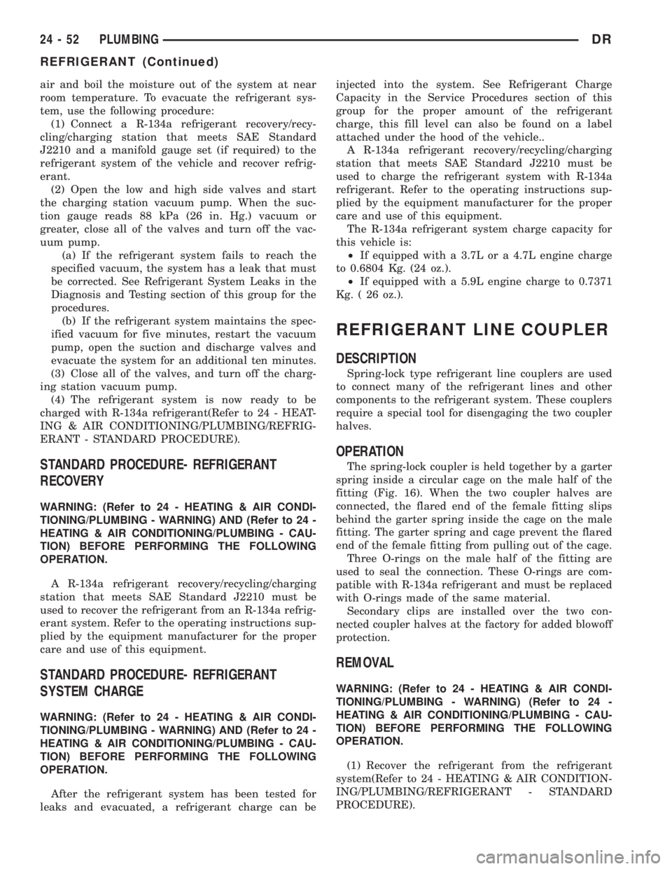
The R-134a refrigerant system charge capacity for
this vehicle is:
²If equipped with a 3.7L or a 4.7L engine charge
to 0.6804 Kg. (24 oz.).
²If equipped with a 5.9L engine charge to 0.7371
Kg. ( 26 oz.).
REFRIGERANT LINE COUPLER
DESCRIPTION
Spring-lock type refrigerant line couplers are used
to connect many of the refrigerant lines and other
components to the refrigerant system. These couplers
require a special tool for disengaging the two coupler
halves.
OPERATION
The spring-lock coupler is held together by a garter
spring inside a circular cage on the male half of the
fitting (Fig. 16). When the two coupler halves are
connected, the flared end of the female fitting slips
behind the garter spring inside the cage on the male
fitting. The garter spring and cage prevent the flared
end of the female fitting from pulling out of the cage.
Three O-rings on the male half of the fitting are
used to seal the connection. These O-rings are com-
patible with R-134a refrigerant and must be replaced
with O-rings made of the same material.
Secondary clips are installed over the two con-
nected coupler halves at the factory for added blowoff
protection.
REMOVAL
WARNING: (Refer to 24 - HEATING & AIR CONDI-
TIONING/PLUMBING - WARNING) (Refer to 24 -
HEATING & AIR CONDITIONING/PLUMBING - CAU-
TION) BEFORE PERFORMING THE FOLLOWING
OPERATION.
(1) Recover the refrigerant from the refrigerant
system(Refer to 24 - HEATING & AIR CONDITION-
ING/PLUMBING/REFRIGERANT - STANDARD
PROCEDURE).
24 - 52 PLUMBINGDR
REFRIGERANT (Continued)
Page 2860 of 2895

BRAKE SYSTEM - DIAGNOSIS AND
TESTING, BASE........................5-2
BRAKE TRANSMISSION SHIFT
INTERLOCK - ADJUSTMENTS . . . 21-195,21-376,
21-540
BRAKE TRANSMISSION SHIFT
INTERLOCK - DIAGNOSIS AND
TESTING..............21-195,21-375,21-540
BRAKE TRANSMISSION SHIFT
INTERLOCK SYSTEM - DESCRIPTION . . . 21-194,
21-375,21-540
BRAKE TRANSMISSION SHIFT
INTERLOCK SYSTEM - OPERATION.....21-194,
21-375,21-540
BRAKE/PARK BRAKE INDICATOR -
DESCRIPTION.......................8J-18
BRAKE/PARK BRAKE INDICATOR -
OPERATION.........................8J-19
BRAKES - ABS - DESCRIPTION...........5-39
BRAKES - ABS - OPERATION............5-39
BRAKES, SPECIAL TOOLS - BASE.........5-5
BREAK-IN - STANDARD PROCEDURE,
A/C COMPRESSOR CLUTCH............24-10
BREATHER - INSTALLATION,
CRANKCASE........................9-292
BREATHER - REMOVAL, CRANKCASE.....9-291
BUCKLE - INSTALLATION, FRONT
OUTBOARD SEAT BELT................8O-34
BUCKLE - REMOVAL, FRONT OUTBOARD
SEAT BELT .........................8O-33
BUILT-IN INDICATOR TEST - STANDARD
PROCEDURE........................8F-10
BUMPER - INSTALLATION, FRONT........13-2
BUMPER - INSTALLATION, JOUNCE.......2-40
BUMPER - INSTALLATION, REAR.........13-4
BUMPER - REMOVAL, FRONT............13-2
BUMPER - REMOVAL, JOUNCE...........2-40
BUMPER - REMOVAL, REAR.............13-4
BUMPERS (3500) - INSTALLATION,
AUXILIARY SPRING....................2-40
BUMPERS (3500) - REMOVAL,
AUXILIARY SPRING....................2-40
BURNT FLUID - DIAGNOSIS AND
TESTING, CAUSES OF....21-201,21-381,21-541
BUSHING - INSTALLATION.............19-18
BUSHING - INSTALLATION,
DISTRIBUTOR.......................9-258
BUSHING - INSTALLATION, EXTENSION
HOUSING..........................21-200
BUSHING - INSTALLATION, TORSION
BAR CROSS MEMBER..................2-14
BUSHING - REMOVAL.................19-18
BUSHING - REMOVAL, DISTRIBUTOR.....9-258
BUSHING - REMOVAL, EXTENSION
HOUSING..........................21-200
BUSHING - REMOVAL, TORSION BAR
CROSSMEMBER......................2-12
BUSHING AND SEAL - INSTALLATION,
EXTENSION HOUSING..........21-616,21-682
BUSHING AND SEAL - REMOVAL,
EXTENSION HOUSING..........21-616,21-682
BUSHINGS - 2WD (LD) - INSTALLATION,
LOWER CONTROL ARM................2-14
BUSHINGS - 2WD (LD) - REMOVAL,
LOWER CONTROL ARM................2-12
BUSHINGS - 4WD (LD) - INSTALLATION,
LOWER CONTROL ARM
................2-13
BUSHINGS - 4WD (LD) - REMOVAL,
LOWER CONTROL ARM
................2-12
BUSHINGS - INSTALLATION
.............2-39
BUSHINGS - REMOVAL
.................2-39
BUZZ, SQUEAK & RATTLE - STANDARD
PROCEDURE
........................23-11
BYPASS - DESCRIPTION, WATER PUMP
. . . 7-64
BYPASS - OPERATION, WATER PUMP
.....7-65
BYPASS HOSE WITH AIR CONDITIONING
- INSTALLATION, WATER PUMP
..........7-70
BYPASS HOSE WITH AIR CONDITIONING
- REMOVAL, WATER PUMP
..............7-68
BYPASS HOSE WITHOUT AIR
CONDITIONING - INSTALLATION,
WATER PUMP
........................7-70
BYPASS HOSE WITHOUT AIR
CONDITIONING - REMOVAL, WATER
PUMP
..............................7-69
C205F - ADJUSTMENTS, FRONT AXLE
.....3-21
C205F - DESCRIPTION, FRONT AXLE
......3-18C205F - DIAGNOSIS AND TESTING,
FRONT AXLE.........................3-18
C205F - INSTALLATION, FRONT AXLE.....3-21
C205F - OPERATION, FRONT AXLE........3-18
C205F - REMOVAL, FRONT AXLE.........3-21
C205F - SPECIAL TOOLS, FRONT AXLE....3-30
C205F - SPECIFICATIONS, FRONT AXLE....3-29
CAB - INSTALLATION, QUAD...........8O-32
CAB - INSTALLATION, STANDARD.......8O-31
CAB - REMOVAL, QUAD...............8O-29
CAB - REMOVAL, STANDARD...........8O-28
CAB BACK PANEL TRIM -
INSTALLATION, REAR.................23-70
CAB BACK PANEL TRIM - REMOVAL,
REAR..............................23-70
CAB CLEARANCE LAMP - INSTALLATION . . 8L-10
CAB CLEARANCE LAMP - REMOVAL.....8L-10
CABLE - ADJUSTMENTS, THROTTLE
VALVE ......................21-255,21-432
CABLE - DESCRIPTION.................8P-3
CABLE - DESCRIPTION, ANTENNA BODY . . . 8A-4
CABLE - DESCRIPTION, SPARK PLUG.....8I-33
CABLE - DESCRIPTION, THROTTLE
VALVE ......................21-254,21-432
CABLE - DIAGNOSIS AND TESTING,
ANTENNA BODY......................8A-4
CABLE - DIAGNOSIS AND TESTING,
GEARSHIFT............21-209,21-389,21-544
CABLE - INSTALLATION..................8P-6
CABLE - INSTALLATION, ANTENNA BODY . . 8A-6
CABLE - INSTALLATION, CHECK.........23-15
CABLE - INSTALLATION, FRONT
PARKING BRAKE......................5-32
CABLE - INSTALLATION, GEARSHIFT....21-210,
21-390,21-545
CABLE - INSTALLATION, INSTRUMENT
PANEL ANTENNA......................8A-7
CABLE - INSTALLATION, LEFT REAR......5-33
CABLE - INSTALLATION, REAR PARK
BRAKE..............................5-32
CABLE - INSTALLATION, RIGHT REAR.....5-32
CABLE - INSTALLATION, SPARK PLUG....8I-35
CABLE - INSTALLATION, THROTTLE
CONTROL.....................14-51,14-96
CABLE - OPERATION...................8P-3
CABLE - OPERATION, ANTENNA BODY.....8A-4
CABLE - OPERATION, SPARK PLUG.......8I-33
CABLE - REMOVAL....................8P-3
CABLE - REMOVAL, ANTENNA BODY......8A-6
CABLE - REMOVAL, CHECK.............23-15
CABLE - REMOVAL, FRONT PARKING
BRAKE..............................5-31
CABLE - REMOVAL, GEARSHIFT . 21-209,21-389,
21-544
CABLE - REMOVAL, INSTRUMENT PANEL
ANTENNA...........................8A-6
CABLE - REMOVAL, LEFT REAR..........5-32
CABLE - REMOVAL, REAR PARK BRAKE . . . 5-31
CABLE - REMOVAL, RIGHT REAR.........5-31
CABLE - REMOVAL, SPARK PLUG........8I-34
CABLE - REMOVAL, THROTTLE
CONTROL.....................14-49,14-94
CABLE, ADJUSTMENTS - GEARSHIFT . . . 21-211,
21-391,21-546
CABLE ORDER, 8.0L V-10 ENGINE -
SPARK PLUG.........................8I-5
CABLE RESISTANCE, SPECIFICATIONS -
SPARK PLUG.........................8I-5
CABLE ROUTING, 5.7L V-8 ENGINE -
FIRING ORDER........................8I-4
CABLE/HANDLE ASSEMBLY -
INSTALLATION, LATCH RELEASE........23-47
CABLE/HANDLE ASSEMBLY - REMOVAL,
LATCH RELEASE.....................23-47
CABLES - DESCRIPTION, BATTERY.......8F-14
CABLES - DIAGNOSIS AND TESTING,
BATTERY...........................8F-15
CABLES - DIAGNOSIS AND TESTING,
SPARK PLUG........................8I-33
CABLES - INSTALLATION, BATTERY......8F-17
CABLES - OPERATION, BATTERY........8F-14
CABLES - REMOVAL, BATTERY
..........8F-16
CALIBRATION - STANDARD PROCEDURE,
COMPASS
...........................8M-3
CALIPER ADAPTER MOUNT -
INSTALLATION, DISC BRAKE
............5-17
CALIPERS - DESCRIPTION, DISC BRAKE
. . . 5-11
CALIPERS - OPERATION, DISC BRAKE
.....5-12CAM BORE REPAIR - STANDARD
PROCEDURE........................9-315
CAMBER AND CASTER ADJUSTMENT -
STANDARD PROCEDURE.................2-4
CAMBER, CASTER AND TOE
ADJUSTMENT - STANDARD
PROCEDURE..........................2-4
CAM/OVERDRIVE PISTON RETAINER -
ASSEMBLY, OVERRUNNING CLUTCH....21-239,
21-416
CAM/OVERDRIVE PISTON RETAINER -
CLEANING, OVERRUNNING CLUTCH....21-238,
21-416
CAM/OVERDRIVE PISTON RETAINER -
DESCRIPTION, OVERRUNNING CLUTCH . 21-237,
21-415
CAM/OVERDRIVE PISTON RETAINER -
DISASSEMBLY, OVERRUNNING
CLUTCH.....................21-238,21-415
CAM/OVERDRIVE PISTON RETAINER -
INSPECTION, OVERRUNNING CLUTCH . . 21-238,
21-416
CAM/OVERDRIVE PISTON RETAINER -
OPERATION, OVERRUNNING CLUTCH . . . 21-237,
21-415
CAMSHAFT - INSTALLATION . 9-201,9-250,9-320,
9-381
CAMSHAFT - REMOVAL.....9-200,9-250,9-317,
9-380
CAMSHAFT BEARINGS - INSTALLATION . . 9-320,
9-381
CAMSHAFT BEARINGS - REMOVAL . 9-317,9-380
CAMSHAFT CORE HOLE PLUG -
INSTALLATION.......................9-201
CAMSHAFT CORE HOLE PLUG -
REMOVAL............................9-200
CAMSHAFT POSITION SENSOR -
DESCRIPTION.......................14-82
CAMSHAFT POSITION SENSOR -
DESCRIPTION.........................8I-8
CAMSHAFT POSITION SENSOR -
INSTALLATION.......................14-83
CAMSHAFT POSITION SENSOR -
INSTALLATION.......................8I-14
CAMSHAFT POSITION SENSOR -
OPERATION.........................14-82
CAMSHAFT POSITION SENSOR -
OPERATION..........................8I-8
CAMSHAFT POSITION SENSOR -
REMOVAL..........................14-83
CAMSHAFT POSITION SENSOR -
REMOVAL...........................8I-11
CAMSHAFT(S) - DESCRIPTION.......9-24,9-34
CAMSHAFT(S) - INSTALLATION......9-25,9-35
CAMSHAFT(S) - LEFT - DESCRIPTION....9-113
CAMSHAFT(S) - LEFT - INSTALLATION....9-114
CAMSHAFT(S) - LEFT - REMOVAL.......9-113
CAMSHAFT(S) - REMOVAL..........9-24,9-34
CAMSHAFT(S) - RIGHT - DESCRIPTION . . . 9-117
CAMSHAFT(S) - RIGHT - INSTALLATION . . 9-118
CAMSHAFT(S) - RIGHT - REMOVAL......9-117
CANISTER - DESCRIPTION, VAPOR......25-22
CANISTER - INSTALLATION, VAPOR......25-23
CANISTER - OPERATION, VAPOR........25-22
CANISTER - REMOVAL, VAPOR..........25-22
CAP - 5.9L V-8 - DIAGNOSIS AND
TESTING, DISTRIBUTOR...............8I-18
CAP - DESCRIPTION, FUEL FILLER.......25-13
CAP - DESCRIPTION, RADIATOR
PRESSURE..........................7-60
CAP - DIAGNOSIS AND TESTING,
RADIATOR...........................7-61
CAP - OPERATION, FUEL FILLER........25-13
CAP - OPERATION, RADIATOR
PRESSURE..........................7-61
CAPACITIES, SPECIFICATIONS - FLUID......0-5
CAPACITOR - DESCRIPTION, IGNITION
COIL...............................8I-33
CAPACITOR - INSTALLATION, IGNITION
COIL...............................8I-33
CAPACITOR - OPERATION, IGNITION
COIL
...............................8I-33
CAPACITOR - REMOVAL, IGNITION COIL
. . . 8I-33
CAPACITY - SPECIFICATIONS, CHARGE
. . . 24-35
CAP-TO-FILLER NECK SEAL -
DIAGNOSIS AND TESTING, RADIATOR
.....7-61
CARDAN UNIVERSAL JOINTS -
ASSEMBLY, SINGLE
.....................3-9
DRINDEX 5
Description Group-Page Description Group-Page Description Group-Page