2003 DODGE RAM bolt pattern
[x] Cancel search: bolt patternPage 226 of 2895

(19) If exciter ring was removed, position differen-
tial assembly on differential Plug 8965 (Fig. 64) and
place exciter ring on the differential case.
(20) Install the exciter ring on the differential case
evenly with a hammer and brass punch (Fig. 65).
Drive the ring down until it is seated against the
ring gear.
CAUTION: Do not damage exciter ring teeth during
installation.
(21) Install differential in housing and verify gear
backlash and gear contact pattern.(22) Measure final rotating torque with an inch
pound torque wrench. The final pinion rotating
torque plus differential case bearing preload is:
²New Bearings:3.4-5.6 N´m (30-50 in. lbs.)
²Original Bearings:2.8-5.1 N´m (25-45 in. lbs.)
(23) Install axle shafts.
(24) Install the propeller shaft with the reference
marks aligned.
(25) Install differential cover with gasket and
tighten bolts to 40 N´m (30 ft. lbs.).
(26) Fill differential with fluid and tighten fill plug
to 32 N´m (24 ft. lbs.).
Fig. 64 EXCITER RING
1 - EXCITER RING
2 - RING GEAR
3 - DIFFERENTIAL PLUG
4 - DIFFERENTIAL CASE
Fig. 65 EXCITER RING INSTALLATION
1 - EXCITER RING
2 - PUNSH
3 - RING GEAR
DRREAR AXLE - 11 1/2 AA 3 - 153
PINION GEAR/RING GEAR/TONE RING (Continued)
Page 279 of 2895
SPECIFICATIONS
TORQUE SPECIFICATIONS
DESCRIPTION N´m Ft. Lbs. In. Lbs.
Slave Cylinder Nuts 23 17 -
Clutch Master Cylinder
Nuts28 21 -
Pressure Plate Bolts - V6
&V850 37 -
Pressure Plate Bolts - V10 30 22.5 -
Pressure Plate Bolts -
Diesel30 22.5 -
Release Bearing Pivot 23 17 -
Flywheel Bolts 95 70 -
CLUTCH DISC
REMOVAL
(1) Support engine with wood block and adjustable
jack stand, to prevent strain on engine mounts.
(2) Remove transmission and transfer case, if
equipped.
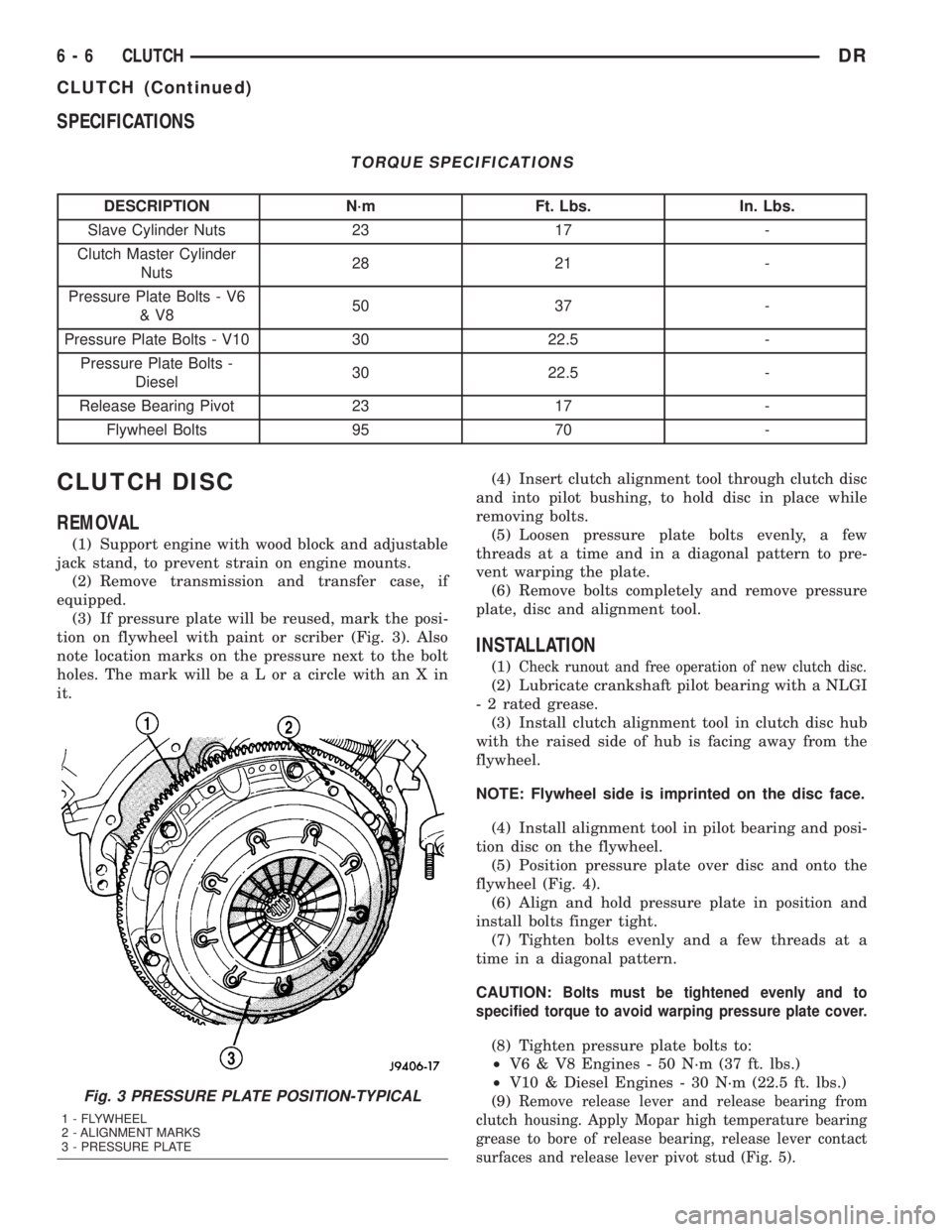
(3) If pressure plate will be reused, mark the posi-
tion on flywheel with paint or scriber (Fig. 3). Also
note location marks on the pressure next to the bolt
holes. The mark will be a L or a circle with an X in
it.(4) Insert clutch alignment tool through clutch disc
and into pilot bushing, to hold disc in place while
removing bolts.
(5) Loosen pressure plate bolts evenly, a few
threads at a time and in a diagonal pattern to pre-
vent warping the plate.
(6) Remove bolts completely and remove pressure
plate, disc and alignment tool.
INSTALLATION
(1)Check runout and free operation of new clutch disc.
(2) Lubricate crankshaft pilot bearing with a NLGI
- 2 rated grease.
(3) Install clutch alignment tool in clutch disc hub
with the raised side of hub is facing away from the
flywheel.
NOTE: Flywheel side is imprinted on the disc face.
(4) Install alignment tool in pilot bearing and posi-
tion disc on the flywheel.
(5) Position pressure plate over disc and onto the
flywheel (Fig. 4).
(6) Align and hold pressure plate in position and
install bolts finger tight.
(7) Tighten bolts evenly and a few threads at a
time in a diagonal pattern.
CAUTION:
Bolts must be tightened evenly and to
specified torque to avoid warping pressure plate cover.
(8) Tighten pressure plate bolts to:
²V6 & V8 Engines - 50 N´m (37 ft. lbs.)
²V10 & Diesel Engines - 30 N´m (22.5 ft. lbs.)
(9)
Remove release lever and release bearing from
clutch housing. Apply Mopar high temperature bearing
grease to bore of release bearing, release lever contact
surfaces and release lever pivot stud (Fig. 5).Fig. 3 PRESSURE PLATE POSITION-TYPICAL
1 - FLYWHEEL
2 - ALIGNMENT MARKS
3 - PRESSURE PLATE
6 - 6 CLUTCHDR
CLUTCH (Continued)
Page 312 of 2895
REMOVAL
WARNING: BECAUSE OF HIGH SPRING PRES-
SURE, DO NOT ATTEMPT TO DISASSEMBLE AUTO-
MATIC TENSIONER. UNIT IS SERVICED AS AN
ASSEMBLY.
(1) Remove accessory drive belt (Refer to 7 -
COOLING/ACCESSORY DRIVE/DRIVE BELTS -
REMOVAL).
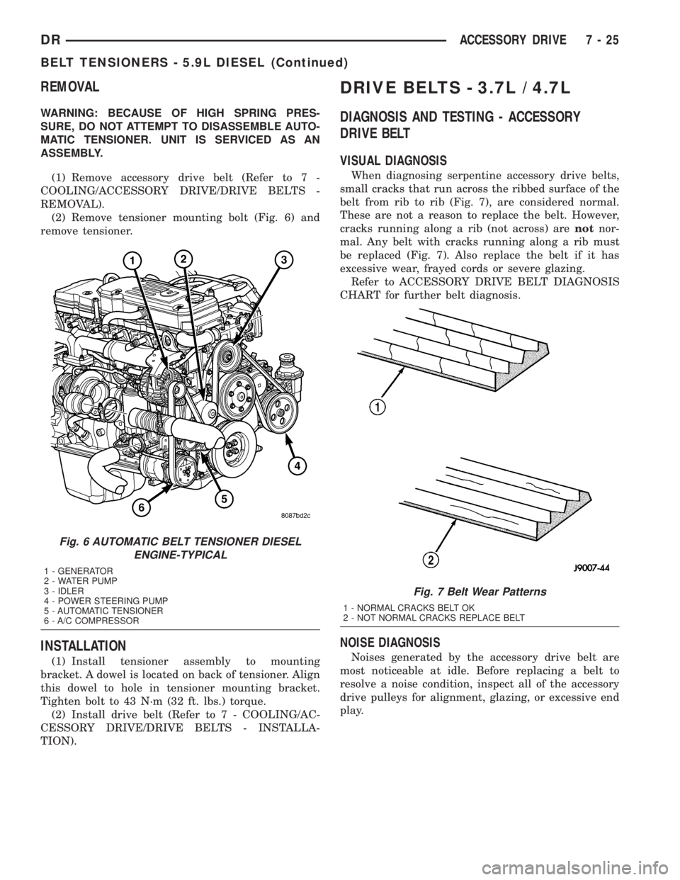
(2) Remove tensioner mounting bolt (Fig. 6) and
remove tensioner.
INSTALLATION
(1) Install tensioner assembly to mounting
bracket. A dowel is located on back of tensioner. Align
this dowel to hole in tensioner mounting bracket.
Tighten bolt to 43 N´m (32 ft. lbs.) torque.
(2) Install drive belt (Refer to 7 - COOLING/AC-
CESSORY DRIVE/DRIVE BELTS - INSTALLA-
TION).
DRIVE BELTS - 3.7L / 4.7L
DIAGNOSIS AND TESTING - ACCESSORY
DRIVE BELT
VISUAL DIAGNOSIS
When diagnosing serpentine accessory drive belts,
small cracks that run across the ribbed surface of the
belt from rib to rib (Fig. 7), are considered normal.
These are not a reason to replace the belt. However,
cracks running along a rib (not across) arenotnor-
mal. Any belt with cracks running along a rib must
be replaced (Fig. 7). Also replace the belt if it has
excessive wear, frayed cords or severe glazing.
Refer to ACCESSORY DRIVE BELT DIAGNOSIS
CHART for further belt diagnosis.
NOISE DIAGNOSIS
Noises generated by the accessory drive belt are
most noticeable at idle. Before replacing a belt to
resolve a noise condition, inspect all of the accessory
drive pulleys for alignment, glazing, or excessive end
play.
Fig. 6 AUTOMATIC BELT TENSIONER DIESEL
ENGINE-TYPICAL
1 - GENERATOR
2 - WATER PUMP
3 - IDLER
4 - POWER STEERING PUMP
5 - AUTOMATIC TENSIONER
6 - A/C COMPRESSOR
Fig. 7 Belt Wear Patterns
1 - NORMAL CRACKS BELT OK
2 - NOT NORMAL CRACKS REPLACE BELT
DRACCESSORY DRIVE 7 - 25
BELT TENSIONERS - 5.9L DIESEL (Continued)
Page 465 of 2895

(3) Check condition of relay terminals and PDC
connector terminals for damage or corrosion. Repair
if necessary before installing relay.
(4) Check for pin height (pin height should be the
same for all terminals within the PDC connector).
Repair if necessary before installing relay.
INSTALLATION
The ASD relay is located in the Power Distribution
Center (PDC) (Fig. 5). Refer to label on PDC cover
for relay location.
(1) Install relay to PDC.
(2) Install cover to PDC.
CAMSHAFT POSITION
SENSOR
DESCRIPTION
3.7L V-6
The Camshaft Position Sensor (CMP) on the 3.7L
6-cylinder engine is bolted to the right-front side of
the right cylinder head.
4.7L V-8
The Camshaft Position Sensor (CMP) on the 4.7L
V-8 engine is bolted to the right-front side of the
right cylinder head.
5.7L V-8
The Camshaft Position Sensor (CMP) on the 5.7L
V-8 engine is located below the generator on the tim-
ing chain / case cover on the right/front side of
engine.
5.9L Diesel
The Camshaft Position Sensor (CMP) on the 5.9L
diesel engine is located below the fuel injection
pump. It is bolted to the back of the timing gear
cover.
5.9L V-8 Gas
The Camshaft Position Sensor (CMP) on the 5.9L
V-8 engine is located inside the distributor.
8.0L V±10
The Camshaft Position Sensor (CMP) on the 8.0L
V-10 engine is located on the timing chain / case
cover on the left/front side of engine.
OPERATION
3.7L V-6
The Camshaft Position Sensor (CMP) sensor on the
3.7L V-6 engine contains a hall effect device referred
to as a sync signal generator. A rotating target wheel
(tonewheel) for the CMP is located at the front of the
camshaft for the right cylinder head (Fig. 6). This
sync signal generator detects notches located on a
tonewheel. As the tonewheel rotates, the notches
pass through the sync signal generator. The signal
from the CMP sensor is used in conjunction with the
Crankshaft Position Sensor (CKP) to differentiate
between fuel injection and spark events. It is also
used to synchronize the fuel injectors with their
respective cylinders.
When the leading edge of the tonewheel notch
enters the tip of the CMP, the interruption of mag-
netic field causes the voltage to switch high, result-
ing in a sync signal of approximately 5 volts.
When the trailing edge of the tonewheel notch
leaves then tip of the CMP, the change of the mag-
netic field causes the sync signal voltage to switch
low to 0 volts.
4.7L V-8
The CMP sensor on the 4.7L engine contains a hall
effect device called a sync signal generator to gener-
ate a fuel sync signal. This sync signal generator
detects notches located on a tonewheel. The tone-
wheel is located at the front of the camshaft for the
right cylinder head (Fig. 7). As the tonewheel rotates,
the notches pass through the sync signal generator.
The pattern of the notches (viewed counter-clockwise
from front of engine) is: 1 notch, 2 notches, 3 notches,
Fig. 5 PDC LOCATION
1 - BATTERY
2 - PDC (POWER DISTRIBUTION CENTER)
8I - 8 IGNITION CONTROLDR
AUTOMATIC SHUT DOWN RELAY (Continued)
Page 552 of 2895

(4) Install the cluster bezel onto the instrument
panel (Fig. 9).
(5) Connect the battery negative cable.
HEADLAMP UNIT
REMOVAL
(1) Disconnect and isolate the battery negative
cable.
(2) Remove the push pins attaching the seal to the
fender.
(3) Remove the bolts attaching the headlamp unit
to the fender (Fig. 10).
(4) Remove the bulb sockets from the headlamp
unit
(5) Separate headlamp unit from vehicle.
INSTALLATION
CAUTION: Do not touch the bulb glass with fingers
or other oily surfaces. Reduced bulb life will result.
(1) Install the bulb sockets for the front park/turn
signal and headlamp.
(2) Position headlamp unit in inner fender panel.
(3) Install the bolts attaching headlamp unit to the
fender (Fig. 10).
(4) Align the seal and install the push pins.
(5) Connect the battery negative cable.
ADJUSTMENTS
Headlamps can be aligned using the screen method
provided in this section. Alignment Tool C-4466-A or
equivalent can also be used. Refer to instructions
provided with the tool for proper procedures.
LAMP ALIGNMENT SCREEN PREPARATION
(1) Position vehicle on a level surface perpendicu-
lar to a flat wall 7.62 meters (25 ft) away from front
of headlamp lens (Fig. 11).
(2) If necessary, tape a line on the floor 7.62
meters (25 ft) away from and parallel to the wall.
(3) Up 1.27 meters (5 feet) from the floor, tape a
line on the wall at the centerline of the vehicle. Sight
along the centerline of the vehicle (from rear of vehi-
cle forward) to verify accuracy of the line placement.
(4) Rock vehicle side-to-side three times to allow
suspension to stabilize.
(5) Jounce front suspension three times by pushing
downward on front bumper and releasing.
(6) Measure the distance from the center of head-
lamp lens to the floor. Transfer measurement to the
alignment screen (with tape). Use this line for
up/down adjustment reference.
(7) Measure distance from the centerline of the
vehicle to the center of each headlamp being aligned.
Transfer measurements to screen (with tape) to each
side of vehicle centerline. Use these lines for left/
right adjustment reference.
VEHICLE PREPARATION FOR HEADLAMP
ALIGNMENT
(1) Verify headlamp dimmer switch and high beam
indicator operation.
(2) Correct defective components that could hinder
proper headlamp alignment.
(3) Verify proper tire inflation.
(4) Clean headlamp lenses.
(5) Verify that luggage area is not heavily loaded.
(6) Fuel tank should be FULL. Add 2.94 kg (6.5
lbs.) of weight over the fuel tank for each estimated
gallon of missing fuel.
HEADLAMP ALIGNMENT
A properly aimed low beam headlamp will project
top edge of high intensity pattern on screen from 50
mm (2 in.) above to 50 mm (2 in.) below headlamp
centerline. The side-to-side outboard edge of high
intensity pattern should be from 50 mm (2 in.) left to
50 mm (2 in.) right of headlamp centerline (Fig. 11).
The preferred headlamp alignment is 1(down
for the up/down adjustment and 0 for the left/
right adjustment.The high beam pattern should be
correct when the low beams are aligned properly.
To adjust low beam headlamp, rotate alignment
screws to achieve the specified aim.
Fig. 10 HEADLAMP Ð TYPICAL
1 - SEAL
2 - PUSH PIN
3 - SCREW
4 - HEADLAMP UNIT
DRLAMPS/LIGHTING - EXTERIOR 8L - 15
HEADLAMP SWITCH (Continued)
Page 1297 of 2895
STANDARD PROCEDURE
CONNECTING ROD BEARING FITTING
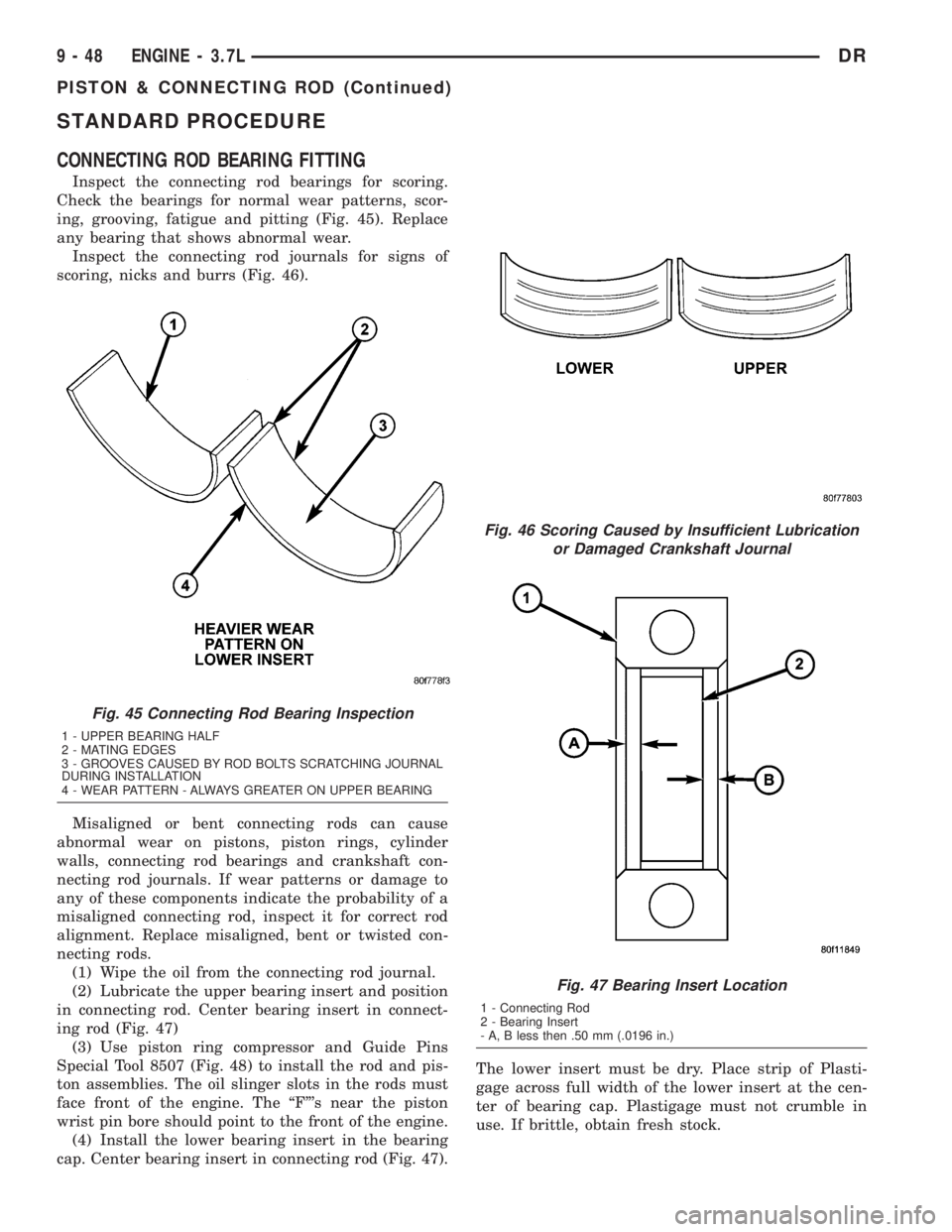
Inspect the connecting rod bearings for scoring.
Check the bearings for normal wear patterns, scor-
ing, grooving, fatigue and pitting (Fig. 45). Replace
any bearing that shows abnormal wear.
Inspect the connecting rod journals for signs of
scoring, nicks and burrs (Fig. 46).
Misaligned or bent connecting rods can cause
abnormal wear on pistons, piston rings, cylinder
walls, connecting rod bearings and crankshaft con-
necting rod journals. If wear patterns or damage to
any of these components indicate the probability of a
misaligned connecting rod, inspect it for correct rod
alignment. Replace misaligned, bent or twisted con-
necting rods.
(1) Wipe the oil from the connecting rod journal.
(2) Lubricate the upper bearing insert and position
in connecting rod. Center bearing insert in connect-
ing rod (Fig. 47)
(3) Use piston ring compressor and Guide Pins
Special Tool 8507 (Fig. 48) to install the rod and pis-
ton assemblies. The oil slinger slots in the rods must
face front of the engine. The ªFº's near the piston
wrist pin bore should point to the front of the engine.
(4) Install the lower bearing insert in the bearing
cap. Center bearing insert in connecting rod (Fig. 47).The lower insert must be dry. Place strip of Plasti-
gage across full width of the lower insert at the cen-
ter of bearing cap. Plastigage must not crumble in
use. If brittle, obtain fresh stock.
Fig. 45 Connecting Rod Bearing Inspection
1 - UPPER BEARING HALF
2 - MATING EDGES
3 - GROOVES CAUSED BY ROD BOLTS SCRATCHING JOURNAL
DURING INSTALLATION
4 - WEAR PATTERN - ALWAYS GREATER ON UPPER BEARING
Fig. 46 Scoring Caused by Insufficient Lubrication
or Damaged Crankshaft Journal
Fig. 47 Bearing Insert Location
1 - Connecting Rod
2 - Bearing Insert
- A, B less then .50 mm (.0196 in.)
9 - 48 ENGINE - 3.7LDR
PISTON & CONNECTING ROD (Continued)
Page 1377 of 2895
CONNECTING ROD BEARINGS
STANDARD PROCEDURE - CONNECTING ROD
BEARING FITTING
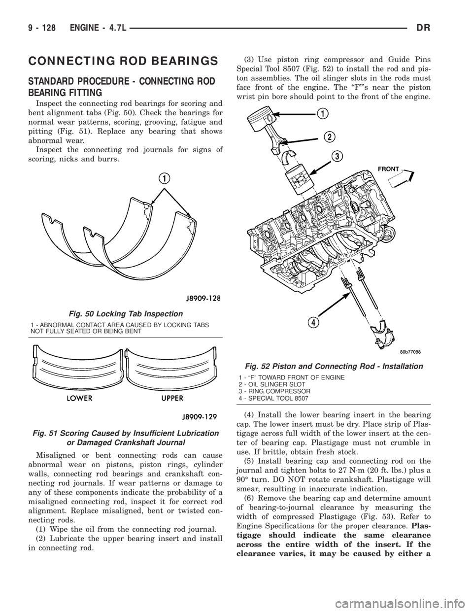
Inspect the connecting rod bearings for scoring and
bent alignment tabs (Fig. 50). Check the bearings for
normal wear patterns, scoring, grooving, fatigue and
pitting (Fig. 51). Replace any bearing that shows
abnormal wear.
Inspect the connecting rod journals for signs of
scoring, nicks and burrs.
Misaligned or bent connecting rods can cause
abnormal wear on pistons, piston rings, cylinder
walls, connecting rod bearings and crankshaft con-
necting rod journals. If wear patterns or damage to
any of these components indicate the probability of a
misaligned connecting rod, inspect it for correct rod
alignment. Replace misaligned, bent or twisted con-
necting rods.
(1) Wipe the oil from the connecting rod journal.
(2) Lubricate the upper bearing insert and install
in connecting rod.(3) Use piston ring compressor and Guide Pins
Special Tool 8507 (Fig. 52) to install the rod and pis-
ton assemblies. The oil slinger slots in the rods must
face front of the engine. The ªFº's near the piston
wrist pin bore should point to the front of the engine.
(4) Install the lower bearing insert in the bearing
cap. The lower insert must be dry. Place strip of Plas-
tigage across full width of the lower insert at the cen-
ter of bearing cap. Plastigage must not crumble in
use. If brittle, obtain fresh stock.
(5) Install bearing cap and connecting rod on the
journal and tighten bolts to 27 N´m (20 ft. lbs.) plus a
90É turn. DO NOT rotate crankshaft. Plastigage will
smear, resulting in inaccurate indication.
(6) Remove the bearing cap and determine amount
of bearing-to-journal clearance by measuring the
width of compressed Plastigage (Fig. 53). Refer to
Engine Specifications for the proper clearance.Plas-
tigage should indicate the same clearance
across the entire width of the insert. If the
clearance varies, it may be caused by either a
Fig. 50 Locking Tab Inspection
1 - ABNORMAL CONTACT AREA CAUSED BY LOCKING TABS
NOT FULLY SEATED OR BEING BENT
Fig. 51 Scoring Caused by Insufficient Lubrication
or Damaged Crankshaft Journal
Fig. 52 Piston and Connecting Rod - Installation
1 - ªFº TOWARD FRONT OF ENGINE
2 - OIL SLINGER SLOT
3 - RING COMPRESSOR
4 - SPECIAL TOOL 8507
9 - 128 ENGINE - 4.7LDR
Page 1445 of 2895
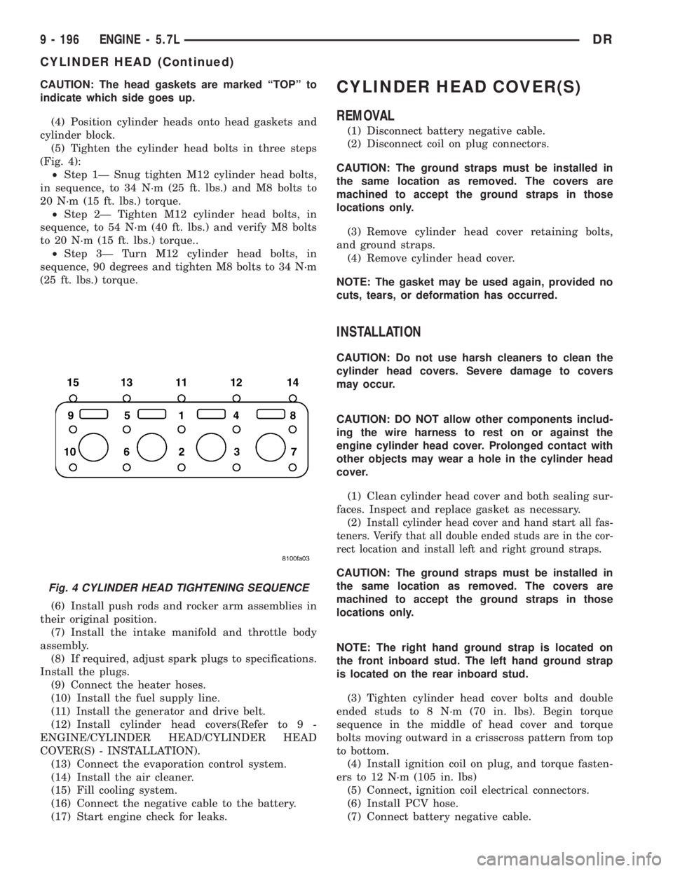
CAUTION: The head gaskets are marked ªTOPº to
indicate which side goes up.
(4) Position cylinder heads onto head gaskets and
cylinder block.
(5) Tighten the cylinder head bolts in three steps
(Fig. 4):
²Step 1Ð Snug tighten M12 cylinder head bolts,
in sequence, to 34 N´m (25 ft. lbs.) and M8 bolts to
20 N´m (15 ft. lbs.) torque.
²Step 2Ð Tighten M12 cylinder head bolts, in
sequence, to 54 N´m (40 ft. lbs.) and verify M8 bolts
to 20 N´m (15 ft. lbs.) torque..
²Step 3Ð Turn M12 cylinder head bolts, in
sequence, 90 degrees and tighten M8 bolts to 34 N´m
(25 ft. lbs.) torque.
(6) Install push rods and rocker arm assemblies in
their original position.
(7) Install the intake manifold and throttle body
assembly.
(8) If required, adjust spark plugs to specifications.
Install the plugs.
(9) Connect the heater hoses.
(10) Install the fuel supply line.
(11) Install the generator and drive belt.
(12) Install cylinder head covers(Refer to 9 -
ENGINE/CYLINDER HEAD/CYLINDER HEAD
COVER(S) - INSTALLATION).
(13) Connect the evaporation control system.
(14) Install the air cleaner.
(15) Fill cooling system.
(16) Connect the negative cable to the battery.
(17) Start engine check for leaks.CYLINDER HEAD COVER(S)
REMOVAL
(1) Disconnect battery negative cable.
(2) Disconnect coil on plug connectors.
CAUTION: The ground straps must be installed in
the same location as removed. The covers are
machined to accept the ground straps in those
locations only.
(3) Remove cylinder head cover retaining bolts,
and ground straps.
(4) Remove cylinder head cover.
NOTE: The gasket may be used again, provided no
cuts, tears, or deformation has occurred.
INSTALLATION
CAUTION: Do not use harsh cleaners to clean the
cylinder head covers. Severe damage to covers
may occur.
CAUTION: DO NOT allow other components includ-
ing the wire harness to rest on or against the
engine cylinder head cover. Prolonged contact with
other objects may wear a hole in the cylinder head
cover.
(1) Clean cylinder head cover and both sealing sur-
faces. Inspect and replace gasket as necessary.
(2)
Install cylinder head cover and hand start all fas-
teners. Verify that all double ended studs are in the cor-
rect location and install left and right ground straps.
CAUTION: The ground straps must be installed in
the same location as removed. The covers are
machined to accept the ground straps in those
locations only.
NOTE: The right hand ground strap is located on
the front inboard stud. The left hand ground strap
is located on the rear inboard stud.
(3) Tighten cylinder head cover bolts and double
ended studs to 8 N´m (70 in. lbs). Begin torque
sequence in the middle of head cover and torque
bolts moving outward in a crisscross pattern from top
to bottom.
(4) Install ignition coil on plug, and torque fasten-
ers to 12 N´m (105 in. lbs)
(5) Connect, ignition coil electrical connectors.
(6) Install PCV hose.
(7) Connect battery negative cable.
Fig. 4 CYLINDER HEAD TIGHTENING SEQUENCE
9 - 196 ENGINE - 5.7LDR
CYLINDER HEAD (Continued)