2003 DODGE RAM bolt pattern
[x] Cancel search: bolt patternPage 1452 of 2895
MAIN BEARING SELECTION CHART - 5.7L
GRADE SIZE mm
(in.)FOR USE WITH
MARKING JOURNAL SIZE
A0.008 mm
U/S64.988±64.995 mm
(0.0004 in.)
U/S(2.5585± 2.5588in.)
BNOMINAL 64.996±65.004 mm
(2.5588±2.5592 in.)
C0.008 mm
O/S65.005±65.012 mm
(0.0004 in.)
O/S(2.5592±2.5595 in.)
INSPECTION
Wipe the inserts clean and inspect for abnormal
wear patterns and for metal or other foreign material
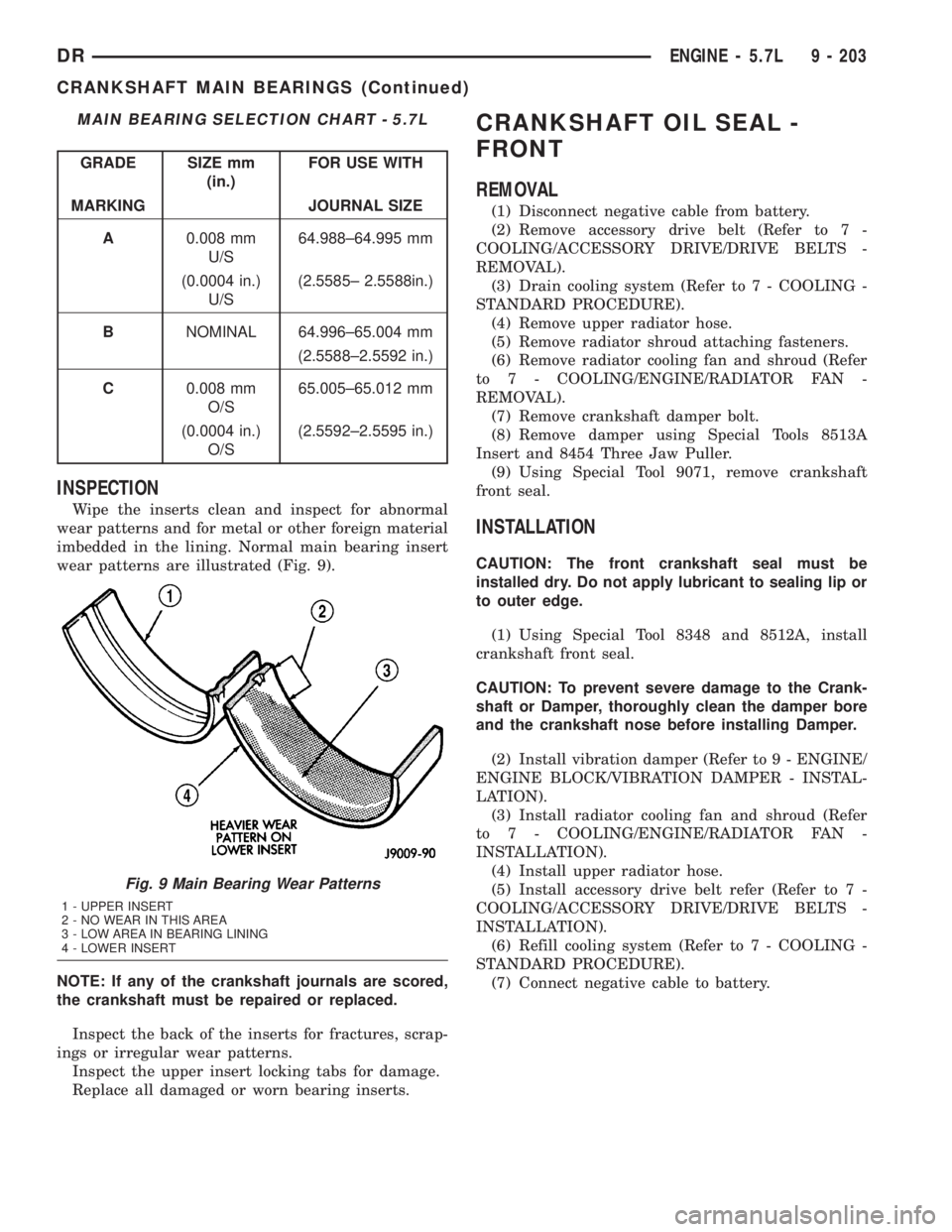
imbedded in the lining. Normal main bearing insert
wear patterns are illustrated (Fig. 9).
NOTE: If any of the crankshaft journals are scored,
the crankshaft must be repaired or replaced.
Inspect the back of the inserts for fractures, scrap-
ings or irregular wear patterns.
Inspect the upper insert locking tabs for damage.
Replace all damaged or worn bearing inserts.
CRANKSHAFT OIL SEAL -
FRONT
REMOVAL
(1) Disconnect negative cable from battery.
(2) Remove accessory drive belt (Refer to 7 -
COOLING/ACCESSORY DRIVE/DRIVE BELTS -
REMOVAL).
(3) Drain cooling system (Refer to 7 - COOLING -
STANDARD PROCEDURE).
(4) Remove upper radiator hose.
(5) Remove radiator shroud attaching fasteners.
(6) Remove radiator cooling fan and shroud (Refer
to 7 - COOLING/ENGINE/RADIATOR FAN -
REMOVAL).
(7) Remove crankshaft damper bolt.
(8) Remove damper using Special Tools 8513A
Insert and 8454 Three Jaw Puller.
(9) Using Special Tool 9071, remove crankshaft
front seal.
INSTALLATION
CAUTION: The front crankshaft seal must be
installed dry. Do not apply lubricant to sealing lip or
to outer edge.
(1) Using Special Tool 8348 and 8512A, install
crankshaft front seal.
CAUTION: To prevent severe damage to the Crank-
shaft or Damper, thoroughly clean the damper bore
and the crankshaft nose before installing Damper.
(2) Install vibration damper (Refer to 9 - ENGINE/
ENGINE BLOCK/VIBRATION DAMPER - INSTAL-
LATION).
(3) Install radiator cooling fan and shroud (Refer
to 7 - COOLING/ENGINE/RADIATOR FAN -
INSTALLATION).
(4) Install upper radiator hose.
(5) Install accessory drive belt refer (Refer to 7 -
COOLING/ACCESSORY DRIVE/DRIVE BELTS -
INSTALLATION).
(6) Refill cooling system (Refer to 7 - COOLING -
STANDARD PROCEDURE).
(7) Connect negative cable to battery.
Fig. 9 Main Bearing Wear Patterns
1 - UPPER INSERT
2 - NO WEAR IN THIS AREA
3 - LOW AREA IN BEARING LINING
4 - LOWER INSERT
DRENGINE - 5.7L 9 - 203
CRANKSHAFT MAIN BEARINGS (Continued)
Page 1453 of 2895
CRANKSHAFT OIL SEAL -
REAR
DIAGNOSIS AND TESTING - REAR SEAL AREA
LEAKS
Since it is sometimes difficult to determine the
source of an oil leak in the rear seal area of the
engine, a more involved inspection is necessary. The
following steps should be followed to help pinpoint
the source of the leak.
If the leakage occurs at the crankshaft rear oil seal
area:
(1) Disconnect the battery.
(2) Raise the vehicle.
(3) Remove torque converter or clutch housing
cover and inspect rear of block for evidence of oil.
Use a black light to check for the oil leak:
(a) Circular spray pattern generally indicates
seal leakage or crankshaft damage.
(b) Where leakage tends to run straight down,
possible causes are a porous block, camshaft bore
cup plugs, oil galley pipe plugs, oil filter runoff,
and main bearing cap to cylinder block mating sur-
faces. See Engine, for proper repair procedures of
these items.
(4) If no leaks are detected, pressurized the crank-
case as outlined in the section, Inspection (Engine oil
Leaks in general)
CAUTION: Do not exceed 20.6 kPa (3 psi).
(5) If the leak is not detected, very slowly turn the
crankshaft and watch for leakage. If a leak is
detected between the crankshaft and seal while
slowly turning the crankshaft, it is possible the
crankshaft seal surface is damaged. The seal area on
the crankshaft could have minor nicks or scratches
that can be polished out with emery cloth.
CAUTION: Use extreme caution when crankshaft
polishing is necessary to remove minor nicks or
scratches. The crankshaft seal flange is specially
machined to complement the function of the rear oil
seal.
(6) For bubbles that remain steady with shaft
rotation, no further inspection can be done until dis-
assembled. (Refer to 9 - ENGINE - DIAGNOSIS AND
TESTING), under the Oil Leak row, for components
inspections on possible causes and corrections.
(7) After the oil leak root cause and appropriate
corrective action have been identified, (Refer to 9 -
ENGINE/ENGINE BLOCK/CRANKSHAFT OIL
SEAL - REAR - REMOVAL).
REMOVAL
NOTE: This procedure can be performed in vehicle.
(1) If being preformed in vehicle, remove the
transmission.
(2) Remove the flexplate (Refer to 9 - ENGINE/
ENGINE BLOCK/FLEX PLATE - REMOVAL).
NOTE: The crankshaft oil seal CAN NOT be reused
after removal.
NOTE: The crankshaft rear oil seal remover Special
Tool 8506 must be installed deeply into the seal.
Continue to tighten the removal tool into the seal
until the tool can not be turned farther. Failure to
install tool correctly the first time will cause tool to
pull free of seal without removing seal from engine.
(3) Using Special Tool 8506, remove the crankshaft
rear oil seal.
INSTALLATION
CAUTION: The rear seal must be installed dry for
proper operation. Do not lubricate the seal lip or
outer edge.
(1) Position the plastic seal guide onto the crank-
shaft rear face. Then position the crankshaft rear oil
seal onto the guide.
(2) Using Special Tools 8349 Crankshaft Rear Oil
Seal Installer and C-4171 Driver Handle, with a
hammer, tap the seal into place. Continue to tap on
the driver handle until the seal installer seats
against the cylinder block crankshaft bore.
(3) Install the flexplate.
(4) Install the transmission.
CRANKSHAFT REAR OIL SEAL
RETAINER
REMOVAL
(1) Disconnect negative cable from battery.
(2) Remove the transmission.
(3) Remove the drive plate / flywheel.
(4) Remove the oil pan (Refer to 9 - ENGINE/LU-
BRICATION/OIL PAN - REMOVAL).
(5) Remove the rear oil seal retainer mounting
bolts.
(6) Carefully remove the retainer from the engine
block.
9 - 204 ENGINE - 5.7LDR
Page 1459 of 2895
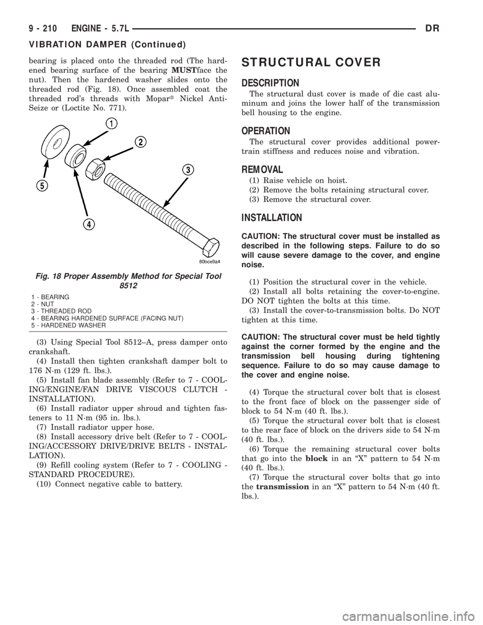
bearing is placed onto the threaded rod (The hard-
ened bearing surface of the bearingMUSTface the
nut). Then the hardened washer slides onto the
threaded rod (Fig. 18). Once assembled coat the
threaded rod's threads with MopartNickel Anti-
Seize or (Loctite No. 771).
(3) Using Special Tool 8512±A, press damper onto
crankshaft.
(4) Install then tighten crankshaft damper bolt to
176 N´m (129 ft. lbs.).
(5) Install fan blade assembly (Refer to 7 - COOL-
ING/ENGINE/FAN DRIVE VISCOUS CLUTCH -
INSTALLATION).
(6) Install radiator upper shroud and tighten fas-
teners to 11 N´m (95 in. lbs.).
(7) Install radiator upper hose.
(8) Install accessory drive belt (Refer to 7 - COOL-
ING/ACCESSORY DRIVE/DRIVE BELTS - INSTAL-
LATION).
(9) Refill cooling system (Refer to 7 - COOLING -
STANDARD PROCEDURE).
(10) Connect negative cable to battery.STRUCTURAL COVER
DESCRIPTION
The structural dust cover is made of die cast alu-
minum and joins the lower half of the transmission
bell housing to the engine.
OPERATION
The structural cover provides additional power-
train stiffness and reduces noise and vibration.
REMOVAL
(1) Raise vehicle on hoist.
(2) Remove the bolts retaining structural cover.
(3) Remove the structural cover.
INSTALLATION
CAUTION: The structural cover must be installed as
described in the following steps. Failure to do so
will cause severe damage to the cover, and engine
noise.
(1) Position the structural cover in the vehicle.
(2) Install all bolts retaining the cover-to-engine.
DO NOT tighten the bolts at this time.
(3) Install the cover-to-transmission bolts. Do NOT
tighten at this time.
CAUTION: The structural cover must be held tightly
against the corner formed by the engine and the
transmission bell housing during tightening
sequence. Failure to do so may cause damage to
the cover and engine noise.
(4) Torque the structural cover bolt that is closest
to the front face of block on the passenger side of
block to 54 N´m (40 ft. lbs.).
(5) Torque the structural cover bolt that is closest
to the rear face of block on the drivers side to 54 N´m
(40 ft. lbs.).
(6) Torque the remaining structural cover bolts
that go into theblockin an ªXº pattern to 54 N´m
(40 ft. lbs.).
(7) Torque the structural cover bolts that go into
thetransmissionin an ªXº pattern to 54 N´m (40 ft.
lbs.).
Fig. 18 Proper Assembly Method for Special Tool
8512
1 - BEARING
2 - NUT
3 - THREADED ROD
4 - BEARING HARDENED SURFACE (FACING NUT)
5 - HARDENED WASHER
9 - 210 ENGINE - 5.7LDR
VIBRATION DAMPER (Continued)
Page 1468 of 2895
INSTALLATION
(1) Position the oil pump onto the crankshaft and
install the 4 oil pump retaining bolts.
(2) Tighten the oil pump retaining bolts to 28 N´m
(250 in. lbs.).
(3) Install the timing chain cover(Refer to 9 -
ENGINE/VALVE TIMING/TIMING BELT / CHAIN
COVER(S) - INSTALLATION).
(4) Install the pick-up tube and oil pan(Refer to 9 -
ENGINE/LUBRICATION/OIL PAN - INSTALLA-
TION).
INTAKE MANIFOLD
DESCRIPTION
The intake manifold is made of a composite mate-
rial and features long runners which maximizes low
end torque. The intake manifold uses single plane
sealing which consist of eight individual press in
place port gaskets to prevent leaks.
DIAGNOSIS AND TESTING - INTAKE
MANIFOLD LEAKAGE
An intake manifold air leak is characterized by
lower than normal manifold vacuum. Also, one or
more cylinders may not be functioning.
WARNING: USE EXTREME CAUTION WHEN THE
ENGINE IS OPERATING. DO NOT STAND IN A
DIRECT LINE WITH THE FAN. DO NOT PUT YOUR
HANDS NEAR THE PULLEYS, BELTS OR THE FAN.
DO NOT WEAR LOOSE CLOTHING.
(1) Start the engine.(2) Spray a small stream of water at the suspected
leak area.
(3) If a change in RPM is observed the area of the
suspected leak has been found.
(4) Repair as required.
REMOVAL
(1) Disconnect negative cable from battery.
(2) Remove resonator assembly and air inlet hose.
(3) Disconnect electrical connectors for the follow-
ing components:
²Manifold Absolute Pressure (MAP) Sensor
²Intake Air Temperature (IAT) Sensor
²Throttle Position (TPS) Sensor
²Coolant Temperature (CTS) Sensor
(4) Disconnect brake booster hose and positive
crankcase ventilation (PCV) hose.
(5) Remove generator and set aside.
NOTE: It is not necessary to remove lines or
remove freon from A/C compressor.
(6) Remove air conditioning compressor and set
aside..
(7) Bleed fuel system (Refer to 14 - FUEL SYS-
TEM/FUEL DELIVERY - STANDARD PROCE-
DURE).
(8) Remove intake manifold retaining fasteners in
a crisscross pattern starting from the outside bolts
and ending at the middle bolts.
(9) Remove intake manifold and IAFM as an
assembly.
CLEANING
NOTE: There is NO approved repair procedure for
the intake manifold. If severe damage is found dur-
ing inspection, the intake manifold must be
replaced.
Before installing the intake manifold thoroughly
clean the mating surfaces. Use a suitable cleaning
solvent, then air dry.
INSPECTION
(1) Inspect the intake sealing surface for cracks,
nicks and distortion.
(2) Inspect the intake manifold vacuum hose fit-
tings for looseness or blockage.
(3) Inspect the manifold to throttle body mating
surface for cracks, nicks and distortion.
INSTALLATION
(1) Install intake manifold seals.
(2) Position intake manifold and IAFM.
(3) Install intake manifold retaining bolts, and
tighten in sequence from the middle bolts towards
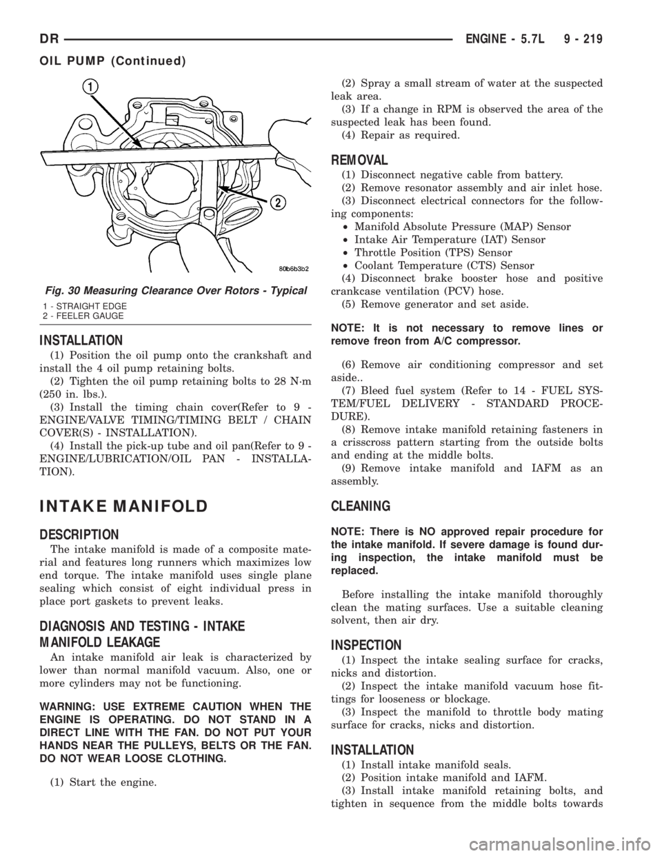
Fig. 30 Measuring Clearance Over Rotors - Typical
1 - STRAIGHT EDGE
2 - FEELER GAUGE
DRENGINE - 5.7L 9 - 219
OIL PUMP (Continued)
Page 1469 of 2895
the outside in a crisscross pattern. Torque fasteners
to 12 N´m (105 in. lbs.).
(4) Connect electrical connectors for the following
components:
²Manifold Absolute Pressure (MAP) Sensor
²Intake Air Temperature (IAT) Sensor
²Throttle Position (TPS) Sensor
²Coolant Temperature (CTS) Sensor
²Idle Air Control (IAC) Motor
(5) Install generator.
(6) Install A/C compressor.
(7) Connect Brake booster hose and Positive crank-
case ventilation (PCV) hose.
(8) Install resonator assembly and air inlet hose.
(9) Connect negative cable to battery.
EXHAUST MANIFOLD
DESCRIPTION
The exhaust manifolds are log style with a pat-
ented flow enhancing design to maximize perfor-
mance. The exhaust manifolds are made of high
silicon molybdenum cast iron. A perforated core
graphite exhaust manifold gasket is used to improve
sealing to the cylinder head. The exhaust manifolds
are covered by a three layer laminated heat shield
for thermal protection and noise reduction. The heat
shields are fastened with a torque prevailing nut
that is backed off slightly to allow for the thermal
expansion of the exhaust manifold.
OPERATION
The exhaust manifolds collect the engine exhaust
exiting the combustion chambers, then channels the
exhaust gases to the exhaust pipes attached to the
manifolds.
REMOVAL
EXHAUST MANIFOLD
(1) Disconnect negative battery cable.
(2) Raise vehicle.
(3) Remove exhaust pipe to manifold bolts.
(4) Lower vehicle.
(5) Install engine support fixture special tool
#8534.
(6) Raise engine enough to remove manifolds.
CAUTION: Do not damage engine harness while
raising the engine.
(7) Remove heat shield.
(8) Remove manifold bolts.
(9) Remove manifold and gasket.
CLEANING
Clean mating surfaces on cylinder head and mani-
fold. Wash with solvent and blow dry with com-
pressed air.
INSPECTION
Inspect manifold for cracks.
Inspect mating surfaces of manifold for flatness
with a straight edge. Gasket surfaces must be flat
within 0.2 mm per 300 mm (0.008 inch per foot).
INSTALLATION
EXHAUST MANIFOLD
(1) Install manifold gasket and manifold.
(2) Install manifold bolts and tighten to 25 N´m
(18 ft. lbs.).
(3) Install heat shield and tighten nuts to 15 N´m
(11 ft. lbs.).
(4) Lower engine.
CAUTION: Do not damage engine harness while
lowering the engine.
(5) Remove engine support fixture from engine.
(6) Raise vehicle.
(7) Tighten right and left side engine mount
through bolts.
(8) Install exhaust flange to pipe bolts.
(9) Lower vehicle.
(10) Connect negative battery cable.
TIMING/CHAIN COVER
REMOVAL
(1) Disconnect the battery negative cable.
(2) Remove air cleaner assembly.
(3) Drain cooling system.
(4) Remove accessory drive belt.
(5) Remove fan and fan drive assembly (Refer to 7
- COOLING/ENGINE/FAN DRIVE VISCOUS
CLUTCH - REMOVAL).
(6) Remove coolant bottle and washer bottle.
(7) Remove fan shroud.
NOTE: It is not necessary to disconnect A/C lines or
discharge freon.
(8) Remove A/C compressor and set aside.
(9) Remove the generator.
(10) Remove upper radiator hose.
(11) Disconnect both heater hoses at timing cover.
(12) Disconnect lower radiator hose at engine.
(13) Remove accessory drive belt tensioner and
both idler pulleys.
9 - 220 ENGINE - 5.7LDR
INTAKE MANIFOLD (Continued)
Page 1575 of 2895
(11) Connect battery negative cables.
(12) Check engine oil level and adjust, if necessary.
(13) Start engine and check for oil leaks.
CRANKSHAFT REAR OIL SEAL
RETAINER
REMOVAL
(1) Disconnect the battery negative cables.
(2) Raise vehicle on hoist.
(3) Remove the oil pan drain plug and drain the
engine oil. Re-install plug and torque to 50 N´m (44
ft. lbs.) torque.
(4) Remove transmission and transfer case (if
equipped) from vehicle.
(5) Remove flywheel or torque converter drive
plate.
(6) Disconnect starter cables from starter motor.
(7) Remove starter motor (Refer to 8 - ELECTRI-
CAL/STARTING/STARTER MOTOR - REMOVAL)
and transmission adapter plate assembly.
(8) Remove four (4) oil pan rear bolts. Slide a
feeler guage between the seal retainer and oil pan
gasket to break the seal.
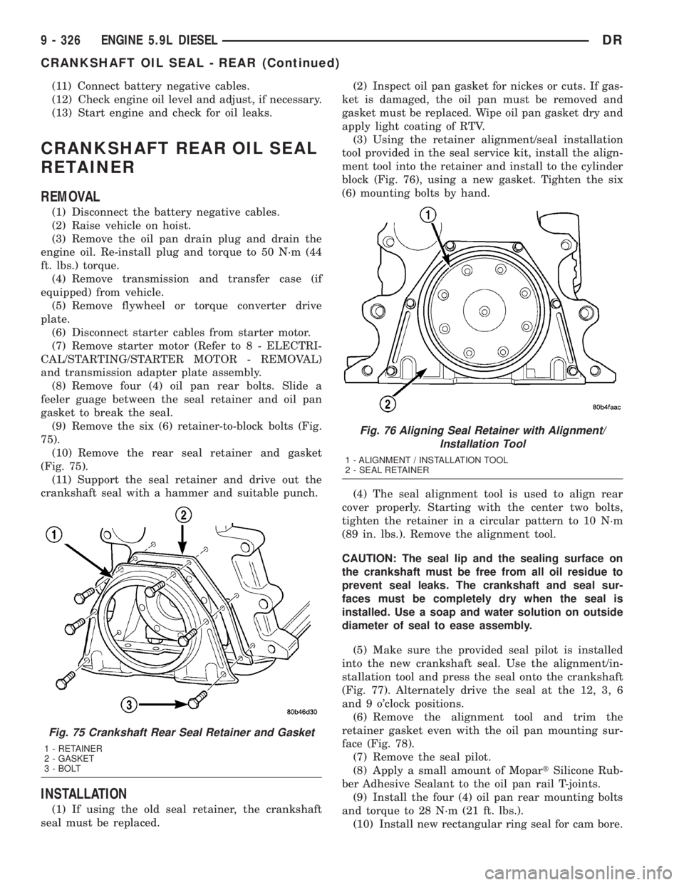
(9) Remove the six (6) retainer-to-block bolts (Fig.
75).
(10) Remove the rear seal retainer and gasket
(Fig. 75).
(11) Support the seal retainer and drive out the
crankshaft seal with a hammer and suitable punch.
INSTALLATION
(1) If using the old seal retainer, the crankshaft
seal must be replaced.(2) Inspect oil pan gasket for nickes or cuts. If gas-
ket is damaged, the oil pan must be removed and
gasket must be replaced. Wipe oil pan gasket dry and
apply light coating of RTV.
(3) Using the retainer alignment/seal installation
tool provided in the seal service kit, install the align-
ment tool into the retainer and install to the cylinder
block (Fig. 76), using a new gasket. Tighten the six
(6) mounting bolts by hand.
(4) The seal alignment tool is used to align rear
cover properly. Starting with the center two bolts,
tighten the retainer in a circular pattern to 10 N´m
(89 in. lbs.). Remove the alignment tool.
CAUTION: The seal lip and the sealing surface on
the crankshaft must be free from all oil residue to
prevent seal leaks. The crankshaft and seal sur-
faces must be completely dry when the seal is
installed. Use a soap and water solution on outside
diameter of seal to ease assembly.
(5) Make sure the provided seal pilot is installed
into the new crankshaft seal. Use the alignment/in-
stallation tool and press the seal onto the crankshaft
(Fig. 77). Alternately drive the seal at the 12, 3, 6
and 9 o'clock positions.
(6) Remove the alignment tool and trim the
retainer gasket even with the oil pan mounting sur-
face (Fig. 78).
(7) Remove the seal pilot.
(8) Apply a small amount of MopartSilicone Rub-
ber Adhesive Sealant to the oil pan rail T-joints.
(9) Install the four (4) oil pan rear mounting bolts
and torque to 28 N´m (21 ft. lbs.).
(10) Install new rectangular ring seal for cam bore.
Fig. 75 Crankshaft Rear Seal Retainer and Gasket
1 - RETAINER
2 - GASKET
3 - BOLT
Fig. 76 Aligning Seal Retainer with Alignment/
Installation Tool
1 - ALIGNMENT / INSTALLATION TOOL
2 - SEAL RETAINER
9 - 326 ENGINE 5.9L DIESELDR
CRANKSHAFT OIL SEAL - REAR (Continued)
Page 2011 of 2895
INPUT SHAFT END PLAY CHECK
NOTE: Overdrive unit must be installed in order to
correctly measure the input shaft end-play.
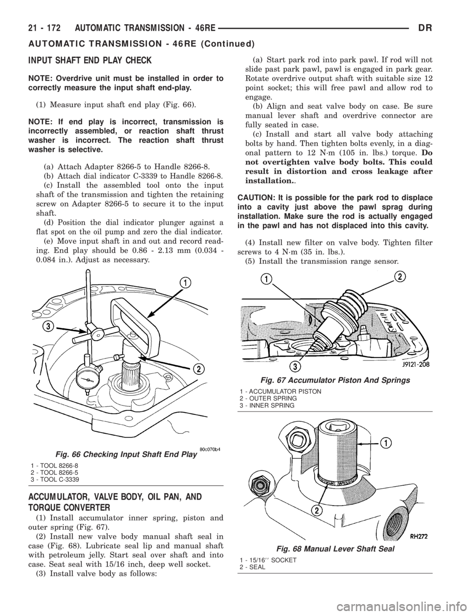
(1) Measure input shaft end play (Fig. 66).
NOTE: If end play is incorrect, transmission is
incorrectly assembled, or reaction shaft thrust
washer is incorrect. The reaction shaft thrust
washer is selective.
(a) Attach Adapter 8266-5 to Handle 8266-8.
(b)
Attach dial indicator C-3339 to Handle 8266-8.
(c) Install the assembled tool onto the input
shaft of the transmission and tighten the retaining
screw on Adapter 8266-5 to secure it to the input
shaft.
(d)
Position the dial indicator plunger against a
flat spot on the oil pump and zero the dial indicator.
(e) Move input shaft in and out and record read-
ing. End play should be 0.86 - 2.13 mm (0.034 -
0.084 in.). Adjust as necessary.
ACCUMULATOR, VALVE BODY, OIL PAN, AND
TORQUE CONVERTER
(1) Install accumulator inner spring, piston and
outer spring (Fig. 67).
(2) Install new valve body manual shaft seal in
case (Fig. 68). Lubricate seal lip and manual shaft
with petroleum jelly. Start seal over shaft and into
case. Seat seal with 15/16 inch, deep well socket.
(3) Install valve body as follows:(a) Start park rod into park pawl. If rod will not
slide past park pawl, pawl is engaged in park gear.
Rotate overdrive output shaft with suitable size 12
point socket; this will free pawl and allow rod to
engage.
(b) Align and seat valve body on case. Be sure
manual lever shaft and overdrive connector are
fully seated in case.
(c) Install and start all valve body attaching
bolts by hand. Then tighten bolts evenly, in a diag-
onal pattern to 12 N´m (105 in. lbs.) torque.Do
not overtighten valve body bolts. This could
result in distortion and cross leakage after
installation..
CAUTION: It is possible for the park rod to displace
into a cavity just above the pawl sprag during
installation. Make sure the rod is actually engaged
in the pawl and has not displaced into this cavity.
(4) Install new filter on valve body. Tighten filter
screws to 4 N´m (35 in. lbs.).
(5) Install the transmission range sensor.
Fig. 66 Checking Input Shaft End Play
1 - TOOL 8266-8
2 - TOOL 8266-5
3 - TOOL C-3339
Fig. 67 Accumulator Piston And Springs
1 - ACCUMULATOR PISTON
2 - OUTER SPRING
3 - INNER SPRING
Fig. 68 Manual Lever Shaft Seal
1 - 15/1688SOCKET
2 - SEAL
21 - 172 AUTOMATIC TRANSMISSION - 46REDR
AUTOMATIC TRANSMISSION - 46RE (Continued)
Page 2076 of 2895
(7) Install thrust bearing in overdrive unit sliding
hub. Use petroleum jelly to hold bearing in position.
CAUTION: Be sure the shoulder on the inside diam-
eter of the bearing is facing forward.
(8) Verify that splines in overdrive planetary gear
and overrunning clutch hub are aligned with Align-
ment Tool 6227-2. Overdrive unit cannot be installed
if splines are not aligned. If splines have rotated out
of alignment, unit will have to be disassembled to
realign splines.
(9) Carefully slide Alignment Tool 6227-2 out of
overdrive planetary gear and overrunning clutch
splines.
(10) Raise overdrive unit and carefully slide it
straight onto intermediate shaft. Insert park rod into
park lock reaction plug at same time. Avoid tilting
overdrive during installation as this could cause
planetary gear and overrunning clutch splines torotate out of alignment. If this occurs, it will be nec-
essary to remove and disassemble overdrive unit to
realign splines.
(11) Work overdrive unit forward on intermediate
shaft until seated against transmission case.
(12) Install bolts attaching overdrive unit to trans-
mission unit. Tighten bolts in diagonal pattern to 34
N´m (25 ft-lbs).
(13) Connect the transmission speed sensor and
overdrive wiring connectors.
(14) Install the transfer case, if equipped.
(15) Align and install rear propeller shaft, if nec-
essary. (Refer to 3 - DIFFERENTIAL & DRIVELINE/
PROPELLER SHAFT/PROPELLER SHAFT -
INSTALLATION)
OVERRUNNING CLUTCH
CAM/OVERDRIVE PISTON
RETAINER
DESCRIPTION
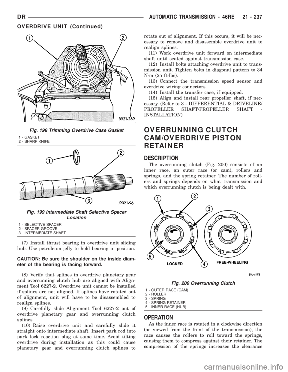
The overrunning clutch (Fig. 200) consists of an
inner race, an outer race (or cam), rollers and
springs, and the spring retainer. The number of roll-
ers and springs depends on what transmission and
which overrunning clutch is being dealt with.
OPERATION
As the inner race is rotated in a clockwise direction
(as viewed from the front of the transmission), the
race causes the rollers to roll toward the springs,
causing them to compress against their retainer. The
compression of the springs increases the clearance
Fig. 198 Trimming Overdrive Case Gasket
1 - GASKET
2 - SHARP KNIFE
Fig. 199 Intermediate Shaft Selective Spacer
Location
1 - SELECTIVE SPACER
2 - SPACER GROOVE
3 - INTERMEDIATE SHAFT
Fig. 200 Overrunning Clutch
1 - OUTER RACE (CAM)
2 - ROLLER
3 - SPRING
4 - SPRING RETAINER
5 - INNER RACE (HUB)
DRAUTOMATIC TRANSMISSION - 46RE 21 - 237
OVERDRIVE UNIT (Continued)