2003 DODGE RAM POWER STEERING PUMP
[x] Cancel search: POWER STEERING PUMPPage 16 of 2895

SPECIALIZED LUBRICANTS AND OILS
Some maintenance or repair procedures may
require the use of specialized lubricants or oils. Con-
sult the appropriate sections in this manual for the
correct application of these lubricants.
DESCRIPTION - POWER STEERING FLUID
MopartATF +4, Automatic Transmission Fluid is
required in the power steering system. Substitute
fluids can induce power steering system failure.
MopartATF +4, Automatic Transmission Fluid
when new is red in color. The ATF is dyed red so it
can be identified from other fluids used in the vehicle
such as engine oil or antifreeze. The red color is not
permanent and is not an indicator of fluid condition.
As the vehicle is driven, the ATF will begin to look
darker in color and may eventually become brown.
This is normal.ATF+4 also has a unique odor that
may change with age. Consequently, odor and color
cannot be used to indicate the fluid condition or the
need for a fluid change.
DESCRIPTION - ENGINE COOLANT
WARNING: ANTIFREEZE IS AN ETHYLENE GLYCOL
BASE COOLANT AND IS HARMFUL IF SWAL-
LOWED OR INHALED. IF SWALLOWED, DRINK
TWO GLASSES OF WATER AND INDUCE VOMIT-
ING. IF INHALED, MOVE TO FRESH AIR AREA.
SEEK MEDICAL ATTENTION IMMEDIATELY. DO NOT
STORE IN OPEN OR UNMARKED CONTAINERS.
WASH SKIN AND CLOTHING THOROUGHLY AFTER
COMING IN CONTACT WITH ETHYLENE GLYCOL.
KEEP OUT OF REACH OF CHILDREN. DISPOSE OF
GLYCOL BASE COOLANT PROPERLY, CONTACT
YOUR DEALER OR GOVERNMENT AGENCY FOR
LOCATION OF COLLECTION CENTER IN YOUR
AREA. DO NOT OPEN A COOLING SYSTEM WHEN
THE ENGINE IS AT OPERATING TEMPERATURE OR
HOT UNDER PRESSURE, PERSONAL INJURY CAN
RESULT. AVOID RADIATOR COOLING FAN WHENENGINE COMPARTMENT RELATED SERVICE IS
PERFORMED, PERSONAL INJURY CAN RESULT.
CAUTION: Use of Propylene Glycol based coolants
is not recommended, as they provide less freeze
protection and less corrosion protection.
The cooling system is designed around the coolant.
The coolant must accept heat from engine metal, in
the cylinder head area near the exhaust valves and
engine block. Then coolant carries the heat to the
radiator where the tube/fin radiator can transfer the
heat to the air.
The use of aluminum cylinder blocks, cylinder
heads, and water pumps requires special corrosion
protection. MopartAntifreeze/Coolant, 5
Year/100,000 Mile Formula (MS-9769), or the equiva-
lent ethylene glycol base coolant with organic corro-
sion inhibitors (called HOAT, for Hybrid Organic
Additive Technology) is recommended. This coolant
offers the best engine cooling without corrosion when
mixed with 50% Ethylene Glycol and 50% distilled
water to obtain a freeze point of -37ÉC (-35ÉF). If it
loses color or becomes contaminated, drain, flush,
and replace with fresh properly mixed coolant solu-
tion.
CAUTION: MoparTAntifreeze/Coolant, 5
Year/100,000 Mile Formula (MS-9769) may not be
mixed with any other type of antifreeze. Mixing of
coolants other than specified (non-HOAT or other
HOAT), may result in engine damage that may not
be covered under the new vehicle warranty, and
decreased corrosion protection.
COOLANT PERFORMANCE
The required ethylene-glycol (antifreeze) and water
mixture depends upon climate and vehicle operating
conditions. The coolant performance of various mix-
tures follows:
Pure Water-Water can absorb more heat than a
mixture of water and ethylene-glycol. This is for pur-
pose of heat transfer only. Water also freezes at a
higher temperature and allows corrosion.
100 percent Ethylene-Glycol-The corrosion
inhibiting additives in ethylene-glycol need the pres-
ence of water to dissolve. Without water, additives
form deposits in system. These act as insulation
causing temperature to rise to as high as 149ÉC
(300ÉF). This temperature is hot enough to melt plas-
tic and soften solder. The increased temperature can
result in engine detonation. In addition, 100 percent
ethylene-glycol freezes at -22ÉC (-8ÉF).
50/50 Ethylene-Glycol and Water-Is the recom-
mended mixture, it provides protection against freez-
ing to -37ÉC (-34ÉF). The antifreeze concentration
Fig. 4 NLGI SYMBOL
1 - WHEEL BEARINGS
2 - CHASSIS LUBRICATION
3 - CHASSIS AND WHEEL BEARINGS
DRLUBRICATION & MAINTENANCE 0 - 3
FLUID TYPES (Continued)
Page 252 of 2895

(2) Install the one mounting bolt for the adjustable
pedal motor (Fig. 46).
(3) Clip the cable fasteners to the support.
(4) Reconnect the electrical connector.
(5) Reconnect the adjustable pedal cables to the
brake and accelerator pedals.
(6) Install the new brake light switch (Refer to 8 -
ELECTRICAL/LAMPS/LIGHTING - EXTERIOR/
BRAKE LAMP SWITCH - REMOVAL).
(7) Install the kneeblocker (Refer to 23 - BODY/IN-
STRUMENT PANEL/STEERING COLUMN OPEN-
ING COVER - INSTALLATION).
(8) Reconnect the negative battery cable.
(9) Check for proper operation of the pedals.
POWER BRAKE BOOSTER
DESCRIPTION
All models use a tandem diaphragm, power brake
booster.
NOTE: The power brake booster is not a repairable
component. The booster must be replaced as an
assembly if diagnosis indicates a malfunction has
occurred.
OPERATION
The booster unit consists of a single housing
divided into two by a tandem diaphragm. The outer
edge of the diaphragm is secured to the housing. The
booster push rod, which connects the booster to the
brake pedal and master cylinder, is attached to the
center of the diaphragm. A check valve is used in the
booster outlet connected to the engine intake mani-
fold. Power assist is generated by utilizing a combi-
nation of vacuum and atmospheric pressure to boost
brake assist.
REMOVAL
(1) Remove master cylinder. (Refer to 5 - BRAKES/
HYDRAULIC/MECHANICAL/MASTER CYLINDER -
REMOVAL).
(2) Disconnect vacuum line at booster.
(3) Remove clip securing booster push rod to brake
pedal (Refer to 5 - BRAKES/HYDRAULIC/MECHAN-
ICAL/PEDAL - REMOVAL). (Fig. 47).
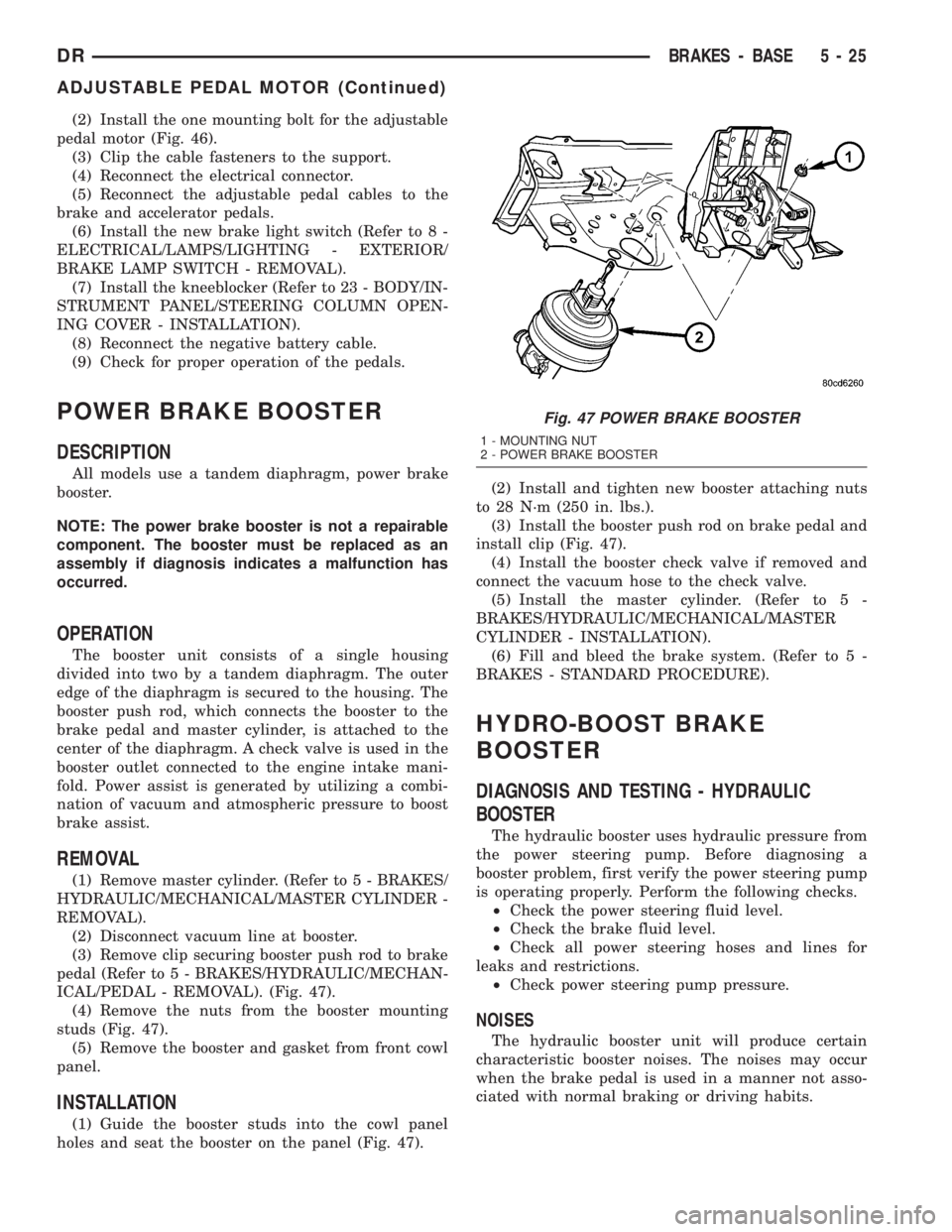
(4) Remove the nuts from the booster mounting
studs (Fig. 47).
(5) Remove the booster and gasket from front cowl
panel.
INSTALLATION
(1) Guide the booster studs into the cowl panel
holes and seat the booster on the panel (Fig. 47).(2) Install and tighten new booster attaching nuts
to 28 N´m (250 in. lbs.).
(3) Install the booster push rod on brake pedal and
install clip (Fig. 47).
(4) Install the booster check valve if removed and
connect the vacuum hose to the check valve.
(5) Install the master cylinder. (Refer to 5 -
BRAKES/HYDRAULIC/MECHANICAL/MASTER
CYLINDER - INSTALLATION).
(6) Fill and bleed the brake system. (Refer to 5 -
BRAKES - STANDARD PROCEDURE).
HYDRO-BOOST BRAKE
BOOSTER
DIAGNOSIS AND TESTING - HYDRAULIC
BOOSTER
The hydraulic booster uses hydraulic pressure from
the power steering pump. Before diagnosing a
booster problem, first verify the power steering pump
is operating properly. Perform the following checks.
²Check the power steering fluid level.
²Check the brake fluid level.
²Check all power steering hoses and lines for
leaks and restrictions.
²Check power steering pump pressure.
NOISES
The hydraulic booster unit will produce certain
characteristic booster noises. The noises may occur
when the brake pedal is used in a manner not asso-
ciated with normal braking or driving habits.
Fig. 47 POWER BRAKE BOOSTER
1 - MOUNTING NUT
2 - POWER BRAKE BOOSTER
DRBRAKES - BASE 5 - 25
ADJUSTABLE PEDAL MOTOR (Continued)
Page 253 of 2895

HISSING
A hissing noise may be noticed when above normal
brake pedal pressure is applied, 40 lbs. or above. The
noise will be more noticeable if the vehicle is not
moving. The noise will increase with the brake pedal
pressure and an increase of system operating temper-
ature.
CLUNK-CHATTER-CLICKING
A clunk-chatter-clicking may be noticed when the
brake pedal is released quickly, after above normal
brake pedal pressure is applied 50-100 lbs..
BOOSTER FUNCTION TEST
With the engine off depress the brake pedal several
times to discharge the accumulator. Then depress the
brake pedal using 40 lbs. of force and start the
engine. The brake pedal should fall and then push
back against your foot. This indicates the booster is
operating properly.
ACCUMULATOR LEAKDOWN
(1) Start the engine, apply the brakes and turn the
steering wheel from lock to lock. This will ensure the
accumulator is charged. Turn off the engine and let
the vehicle sit for one hour. After one hour there
should be at least two power assisted brake applica-
tion with the engine off. If the system does not retain
a charge the booster must be replaced.
(2) With the engine off depress the brake pedal
several times to discharge the accumulator. Grasp
the accumulator and see if it wobbles or turns. If it
does the accumulator has lost a gas charge and the
booster must be replaced.
SEAL LEAKAGE
If the booster leaks from any of the seals the
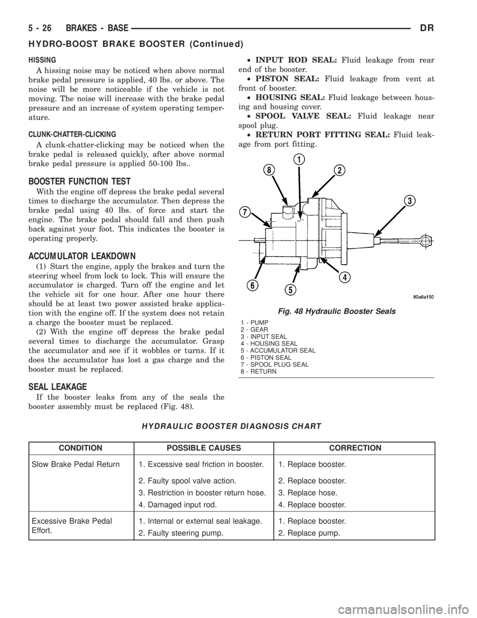
booster assembly must be replaced (Fig. 48).²INPUT ROD SEAL:Fluid leakage from rear
end of the booster.
²PISTON SEAL:Fluid leakage from vent at
front of booster.
²HOUSING SEAL:Fluid leakage between hous-
ing and housing cover.
²SPOOL VALVE SEAL:Fluid leakage near
spool plug.
²RETURN PORT FITTING SEAL:Fluid leak-
age from port fitting.
HYDRAULIC BOOSTER DIAGNOSIS CHART
CONDITION POSSIBLE CAUSES CORRECTION
Slow Brake Pedal Return 1. Excessive seal friction in booster. 1. Replace booster.
2. Faulty spool valve action. 2. Replace booster.
3. Restriction in booster return hose. 3. Replace hose.
4. Damaged input rod. 4. Replace booster.
Excessive Brake Pedal
Effort.1. Internal or external seal leakage. 1. Replace booster.
2. Faulty steering pump. 2. Replace pump.
Fig. 48 Hydraulic Booster Seals
1 - PUMP
2 - GEAR
3 - INPUT SEAL
4 - HOUSING SEAL
5 - ACCUMULATOR SEAL
6 - PISTON SEAL
7 - SPOOL PLUG SEAL
8 - RETURN
5 - 26 BRAKES - BASEDR
HYDRO-BOOST BRAKE BOOSTER (Continued)
Page 254 of 2895

CONDITION POSSIBLE CAUSES CORRECTION
Brakes Self Apply 1. Dump valve faulty. 1. Replace booster.
2. Contamination in hydraulic
system.2. Flush hydraulic system and replace
booster.
3. Restriction in booster return hose. 3. Replace hose.
Booster Chatter, Pedal
Vibration1. Slipping pump belt. 1. Replace power steering belt.
2. Low pump fluid level. 2. Fill pump and check for leaks.
Grabbing Brakes 1. Low pump flow. 1. Test and repair/replace pump.
2. Faulty spool valve action. 2. Replace booster.
STANDARD PROCEDURE - BLEEDING
The hydraulic booster is generally self-bleeding,
this procedure will normally bleed the air from the
booster. Normal driving and operation of the unit will
remove any remaining trapped air.
(1) Fill power steering pump reservoir.
(2) Disconnect fuel shutdown relay and crank the
engine for several seconds, Refer to Fuel System for
relay location and WARNING.
(3) Check fluid level and add if necessary.
(4) Connect fuel shutdown relay and start the
engine.
(5) Turn the steering wheel slowly from lock to
lock twice.
(6) Stop the engine and discharge the accumulator
by depressing the brake pedal 5 times.
(7) Start the engine and turn the steering wheel
slowly from lock to lock twice.
(8) Turn off the engine and check fluid level and
add if necessary.
NOTE: If fluid foaming occurs, wait for foam to dis-
sipate and repeat steps 7 and 8.
REMOVAL
NOTE: If the booster is being replaced because the
power steering fluid is contaminated, flush the
power steering system before replacing the booster.
(1) With engine off depress the brake pedal 5
times to discharge the accumulator.
(2) Remove brake lines from master cylinder.
(3) Remove mounting nuts from the master cylin-
der.
(4) Remove the bracket from the hydraulic booster
lines and master cylinder mounting studs.
(5) Remove the master cylinder.
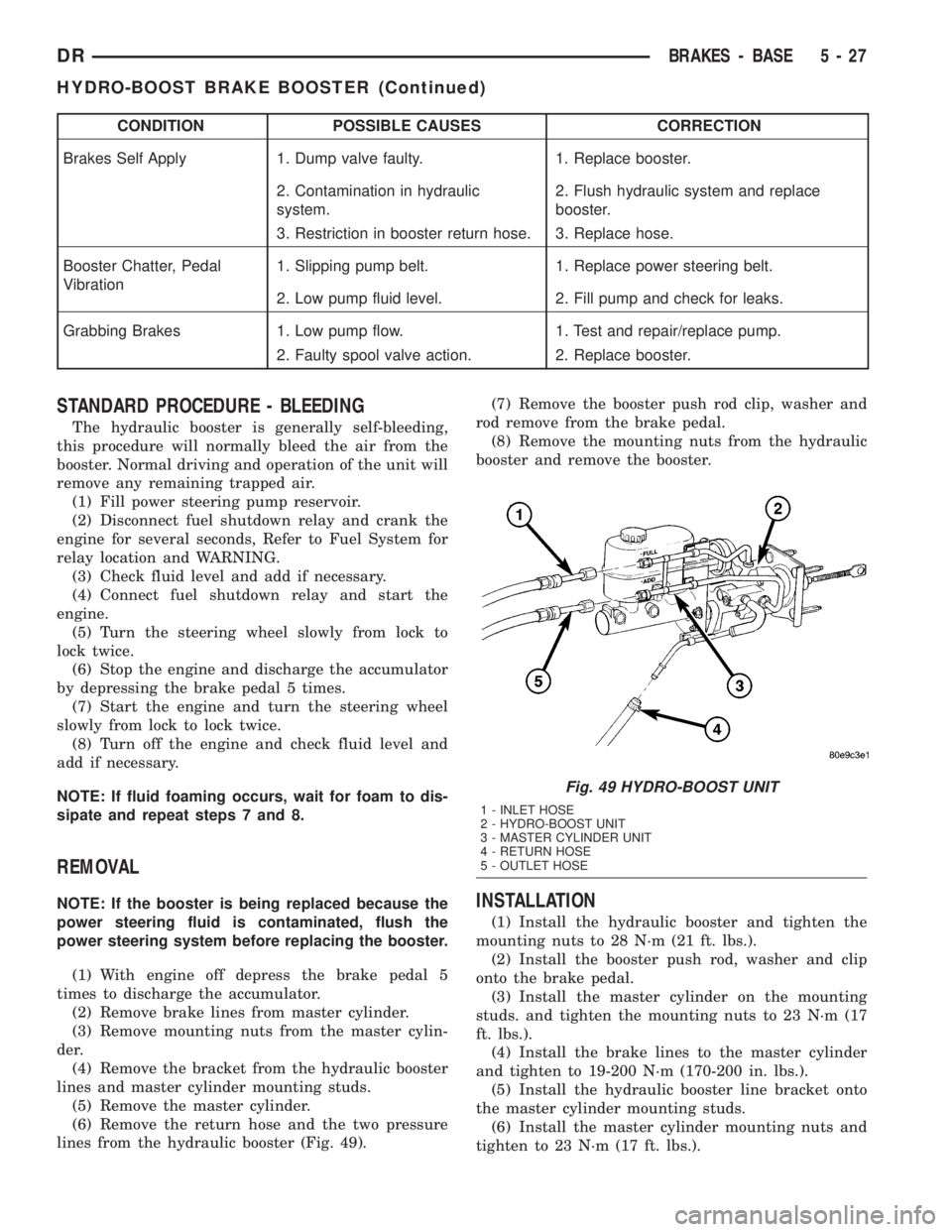
(6) Remove the return hose and the two pressure
lines from the hydraulic booster (Fig. 49).(7) Remove the booster push rod clip, washer and
rod remove from the brake pedal.
(8) Remove the mounting nuts from the hydraulic
booster and remove the booster.INSTALLATION
(1) Install the hydraulic booster and tighten the
mounting nuts to 28 N´m (21 ft. lbs.).
(2) Install the booster push rod, washer and clip
onto the brake pedal.
(3) Install the master cylinder on the mounting
studs. and tighten the mounting nuts to 23 N´m (17
ft. lbs.).
(4) Install the brake lines to the master cylinder
and tighten to 19-200 N´m (170-200 in. lbs.).
(5) Install the hydraulic booster line bracket onto
the master cylinder mounting studs.
(6) Install the master cylinder mounting nuts and
tighten to 23 N´m (17 ft. lbs.).
Fig. 49 HYDRO-BOOST UNIT
1 - INLET HOSE
2 - HYDRO-BOOST UNIT
3 - MASTER CYLINDER UNIT
4 - RETURN HOSE
5 - OUTLET HOSE
DRBRAKES - BASE 5 - 27
HYDRO-BOOST BRAKE BOOSTER (Continued)
Page 255 of 2895

(7) Install the hydraulic booster pressure lines to
the bracket and booster.
(8) Tighten the pressure lines to 41 N´m (30 ft.
lbs.).
NOTE: Inspect o-rings on the pressure line fittings
to insure they are in good condition before installa-
tion. Replace o-rings if necessary.
(9) Install the return hose to the booster.
(10) Bleed base brake system, (Refer to 5 -
BRAKES/HYDRAULIC/MECHANICAL - STAN-
DARD PROCEDURE).
(11) Fill the power steering pump with fluid,
(Refer to 19 - STEERING/PUMP - STANDARD PRO-
CEDURE).
CAUTION: MOPAR (MS-9602) ATF+4 is to be used in
the power steering system. No other power steering
or automatic transmission fluid is to be used in the
system. Damage may result to the power steering
pump and system if any other fluid is used, and do
not overfill.
(12) Bleed the hydraulic booster (Refer to 5 -
BRAKES/HYDRAULIC/MECHANICAL/POWER
BRAKE BOOSTER - STANDARD PROCEDURE).
ROTORS
REMOVAL
REMOVAL - REAR
(1) Raise and support the vehicle
(2) Remove the tire and wheel assembly.
(3) Remove the disc brake caliper, (Refer to 5 -
BRAKES/HYDRAULIC/MECHANICAL/DISC
BRAKE CALIPERS - REMOVAL).
(4) Remove the caliper adapter bolts (Fig.
50).(Refer to 5 - BRAKES/HYDRAULIC/MECHANI-
CAL/DISC BRAKE CALIPER ADAPTER -
REMOVAL)
(5) Remove the retianing clips and rotor assembly
(Fig. 50).
REMOVAL - FRONT
(1) Raise and support the vehicle.
(2) Remove the wheel and tire assembly.
(3) Remove the caliper from the steering knuckle,
(Refer to 5 - BRAKES/HYDRAULIC/MECHANICAL/
DISC BRAKE CALIPERS - REMOVAL) and remove
caliper adapter assembly (Fig. 51).
NOTE: Do not allow brake hose to support caliper
adapter assembly.(4) Remove the rotor from the hub/bearing wheel
studs (Fig. 52) or (Fig. 53).
INSTALLATION
INSTALLATION - REAR
(1) Install the rotor to the axleshaft (Fig. 50).
Fig. 50 REAR ROTOR
1 - ROTOR
2 - CALIPER ADAPTER
3 - CALIPER
Fig. 51 Caliper Adapter Assembly
1 - KNUCKLE
2 - CALIPER
3 - ROTOR
5 - 28 BRAKES - BASEDR
HYDRO-BOOST BRAKE BOOSTER (Continued)
Page 266 of 2895

BRAKES - ABS
TABLE OF CONTENTS
page page
BRAKES - ABS
DESCRIPTION.........................39
OPERATION...........................39
STANDARD PROCEDURE - ABS BRAKE
BLEEDING...........................40
SPECIFICATIONS
TORQUE CHART......................40
FRONT WHEEL SPEED SENSOR
DESCRIPTION.........................41
OPERATION...........................41
REMOVAL.............................41
INSTALLATION.........................42
REAR WHEEL SPEED SENSOR
DIAGNOSIS AND TESTING - REAR WHEEL
ANTILOCK...........................42
REMOVAL.............................42
INSTALLATION.........................43
TONE WHEEL
DIAGNOSIS AND TESTING - REAR WHEEL
SPEED SENSOR......................43HYDRAULIC/MECHANICAL
DESCRIPTION - ELECTRONIC VARIABLE
BRAKE PROPORTIONING...............43
OPERATION - ELECTRONIC VARIABLE
BRAKE PROPORTIONING...............43
HCU (HYDRAULIC CONTROL UNIT)
DESCRIPTION.........................43
OPERATION...........................43
REMOVAL.............................44
INSTALLATION.........................44
R WA L VA LV E
DESCRIPTION.........................44
OPERATION...........................44
REMOVAL.............................45
INSTALLATION.........................45
BRAKES - ABS
DESCRIPTION
The antilock brake system (ABS) is an electroni-
cally operated, three channel brake control system.
The vehicle has Electronic Variable Brake Propor-
tioning (EVBP) designed into the system which elim-
inates the combination/proportioning valve.
The system is designed to prevent wheel lockup
and maintain steering control during braking. Pre-
venting lockup is accomplished by modulating fluid
pressure to the wheel brake units.
The hydraulic system is a three channel design.
The front wheel brakes are controlled individually
and the rear wheel brakes in tandem. The ABS elec-
trical system is separate from other electrical circuits
in the vehicle. A specially programmed controller
antilock brake unit operates the system components.
ABS system major components include:
²Controller Antilock Brakes (CAB)
²Hydraulic Control Unit (HCU)
²Wheel Speed Sensors (WSS)
²ABS Warning Light
OPERATION
Battery voltage is supplied to the CAB. The CAB
performs a system initialization procedure at start
up. A check of the ABS motor is performed at 15
miles per hour. Initialization consists of a static and
dynamic self check of system electrical components.
The static and dynamic checks occurs at ignition
start up. During the dynamic check, the CAB briefly
cycles solenoids to verify operation. An audible noise
may be heard during this self check. This noise
should be considered normal. The ABS motor and
pump are then checked at a speed of 15 mile per
hour.
If an ABS component exhibits a fault during ini-
tialization, the CAB illuminates the amber warning
light and registers a fault code in the microprocessor
memory.
The CAB monitors wheel speed sensor inputs con-
tinuously while the vehicle is in motion. However,
the CAB will not activate any ABS components as
long as sensor inputs indicate normal braking.
During normal braking, the master cylinder, power
booster and wheel brake units all function as they
would in a vehicle without ABS. The HCU compo-
nents are not activated.
DRBRAKES - ABS 5 - 39
Page 307 of 2895

WARNING: DO NOT REMOVE OR LOOSEN THE
RADIATOR CAP WITH THE COOLING SYSTEM HOT
AND UNDER PRESSURE. SERIOUS BURNS FROM
THE COOLANT OR HIGH PRESSURE STEAM CAN
OCCUR.
For 3.7L / 4.7L/5.9L engines, remove the radiator
cap from the coolant degas bottle to add coolant.
SPECIFICATIONS
TORQUE
DESCRIPTION N´m Ft. In.
Lbs. Lbs.
Automatic Belt Tensioner to
BlockÐBolts 41 30 Ð
Automatic Belt Tensioner
PulleyÐBolt 61 45 Ð
Block HeaterÐBolt 2 Ð 17
Generator/Compressor
Mounting BracketÐBolts
# 1 and 2 54 40 Ð
# 3 40 30 Ð
Fan Shroud to Radiator
MountingÐBolts6Ð55
Radiator to Support - Bolts 8.5 Ð 75
Fan Blade to Viscous Fan
DriveÐBolts24 18 Ð
Idler PulleyÐBolt 54 40 Ð
Thermostat HousingÐBolts
- All Except 5.9L13 Ð 112
Thermostat HousingÐBolts
- 5.9L23 16 Ð
Power Steering Oil Cooler
Ð Bolts6Ð55
Transmission Auxiliary Oil
CoolerÐBolts 6 Ð 55
Transmission Oil Cooler
Tube Nuts31.5 24 Ð
Coolant Bottle Ð Bolts 8.5 Ð 75
Transmission Oil Cooler to
Transmission - 5.9L/46RE -
Tube Nuts 31.5 24 Ð
Transmission Oil Cooler to
Transmission - 3.7L/4.7L/
45RFE - Tube Nuts20 18 Ð
Water PumpÐBolts 24 18 Ð
Water Pump Ð Bolts - 4.7L 58 43 Ð
SPECIFICATIONS -
SPECIFICATIONS
DESCRIPTION SPECIFICATION
3.7/4.7L Engine 15.4L (16.2 qts.)- to the
middle of the cold fill
range
5.7L Engine 15.4L (16.2 qts.)- to the
middle of the cold fill
range
5.9L Engine 15.5L (16.3 qts.)- to the
MIN mark after 3 warm
up, cool down cycles
8.0L Engine 24L (25.3 qts.)
5.9L Diesel Engine 28L (29.5 qts.)
SPECIAL TOOLS
COOLING
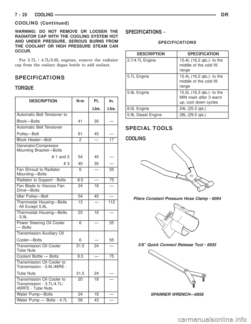
Pliers Constant Pressure Hose Clamp - 6094
3/8º Quick Connect Release Tool - 6935
SPANNER WRENCHÐ6958
7 - 20 COOLINGDR
COOLING (Continued)
Page 309 of 2895

ACCESSORY DRIVE
TABLE OF CONTENTS
page page
BELT TENSIONERS - 3.7L / 4.7L
DESCRIPTION.........................22
OPERATION...........................22
REMOVAL.............................22
INSTALLATION.........................23
BELT TENSIONERS - 5.9L
DESCRIPTION.........................23
OPERATION...........................23
REMOVAL.............................23
INSTALLATION.........................24
BELT TENSIONERS - 5.9L DIESEL
DESCRIPTION.........................24
OPERATION...........................24
REMOVAL.............................25
INSTALLATION.........................25DRIVE BELTS - 3.7L / 4.7L
DIAGNOSIS AND TESTING - ACCESSORY
DRIVE BELT.........................25
REMOVAL.............................27
INSTALLATION.........................27
DRIVE BELTS - 5.9L
DIAGNOSIS AND TESTING - ACCESSORY
DRIVE BELT.........................28
REMOVAL.............................30
INSTALLATION.........................31
DRIVE BELTS - 5.9L DIESEL
DIAGNOSIS AND TESTINGÐACCESSORY
DRIVE BELT.........................31
REMOVAL.............................34
INSTALLATION.........................34
BELT TENSIONERS - 3.7L /
4.7L
DESCRIPTION
Correct drive belt tension is required to ensure
optimum performance of the belt driven engine acces-
sories. If specified tension is not maintained, belt
slippage may cause; engine overheating, lack of
power steering assist, loss of air conditioning capac-
ity, reduced generator output rate, and greatly
reduced belt life.
It is not necessary to adjust belt tension on the
3.7L or 4.7L engine. These engines are equipped with
an automatic belt tensioner (Fig. 1). The tensioner
maintains correct belt tension at all times. Due to
use of this belt tensioner, do not attempt to use a belt
tension gauge on 3.7L or 4.7L engines.
OPERATION
The automatic belt tensioner maintains belt ten-
sion by using internal spring pressure, a pivoting
arm and pulley to press against the drive belt.
REMOVAL
On 3.7L and 4.7L engines, the tensioner is
equipped with an indexing tang on back of ten-
sioner and an indexing stop on tensioner hous-
ing. If a new belt is being installed, tang must
be within approximately 24 mm (.94 inches) ofindexing stop. Belt is considered new if it has
been used 15 minutes or less.
If the above specification cannot be met, check for:
²The wrong belt being installed (incorrect length/
width)
²Worn bearings on an engine accessory (A/C com-
pressor, power steering pump, water pump, idler pul-
ley or generator)
²A pulley on an engine accessory being loose
²Misalignment of an engine accessory
²Belt incorrectly routed.
Fig. 1 AUTOMATIC BELT TENSIONER
1 - AUTOMATIC TENSIONER ASSEMBLY
7 - 22 ACCESSORY DRIVEDR